07: Magnet Sensing
I decided to attempt to make a drawing-tablet-like thing using a magnetic field sensor.
The New Board
For this, I took the board I made during electronics production week and add a TLE493D-A2B6 Hall effect sensor to it. Except that the sensor goes on its own board (since it will be a ‘tablet’) and is linked to the main board with headers and wires.
First, I modified the design of the old board (The KiCad project is here):
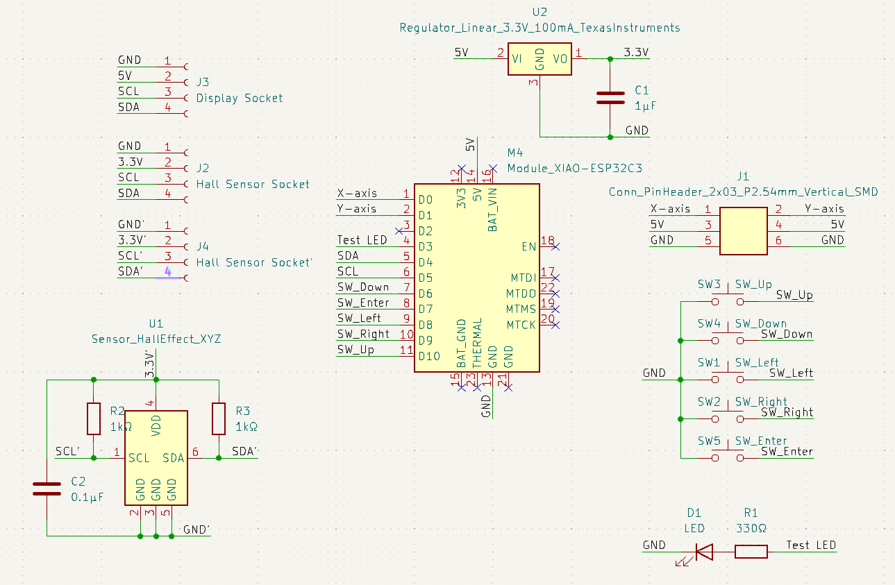
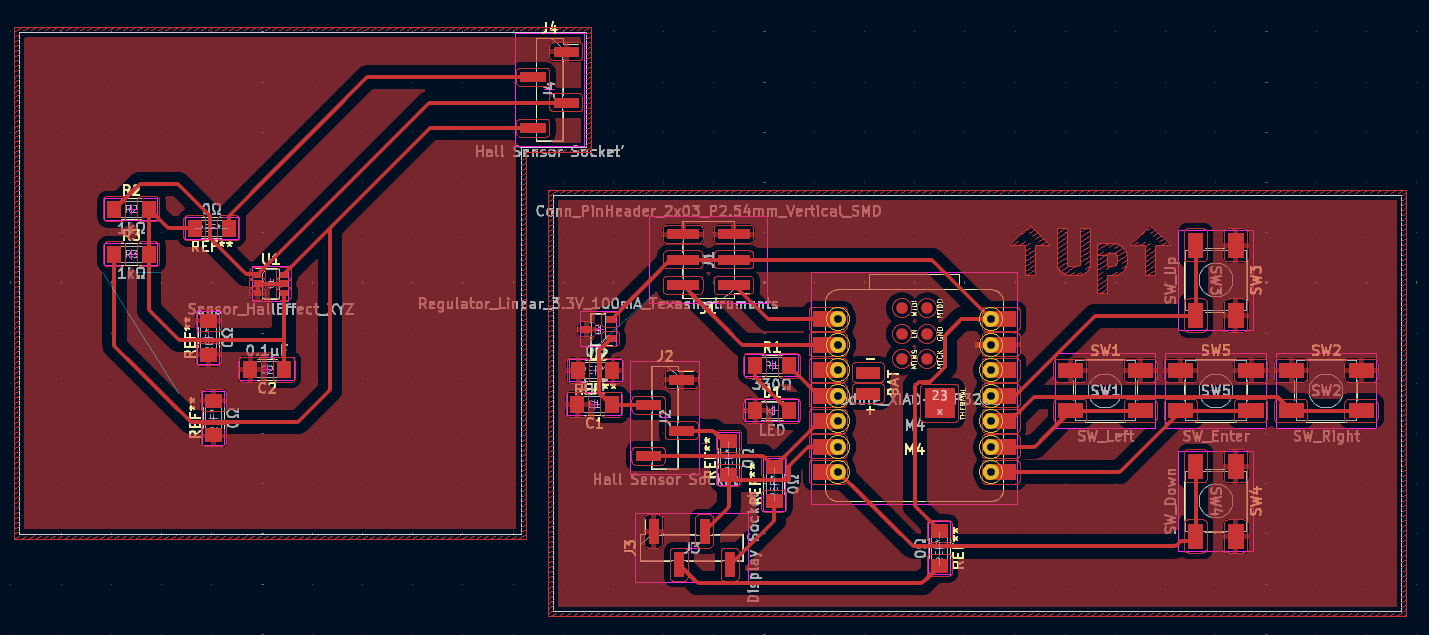
By the way, 0-ohm resistors make nice crossovers. And the solder-paste hot-air combination is amazing.
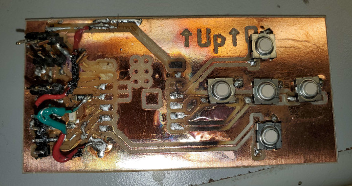
Then came milling the new boards, same as last time. Then came attaching components. There was only one XIAO-ESP32C3 left in supply, so I wanted to reuse the old one. The process of getting the microcontroller off the old board was… terrible. The board was treated with loads and loads of hot air (and a soldering iron on top of that) to get all the joints flowing at the same time. And then finally, the board could be taken off (with no damage to it, thankfully). But the board…
Magnets, How Do They Work?
Now for the programming. I copied my original code over, and used this example and this user manual to program the magnetic field sensor. The setup of the sensor is the same as in the example, but the code that prints the values looks like this:
void handleHallSensor() {
  Wire.requestFrom(HALL_SENSOR_ADDRESS, 6);
  uint32_t bx, by, bz, v4, v5;
  bx = Wire.read();
  by = Wire.read();
  bz = Wire.read();
  Wire.read();
  v4 = Wire.read();
  v5 = Wire.read();
  bx = bx << 4 | v4 >> 4;
  by = by << 4 | (v4 & 0b1111);
  bz = bz << 4 | (v5 & 0b1111);

  Serial.printf("B: %d, %d, %d\n", bx, by, bz);
}
I tested this with a magnet and it does seem to read a magnetic field. Now how do I turn this into a position? This requires knowing how magnets work. What did I get myself into?
Well, direction is easy (or at least that’s what it looks like)
Getting the magnitude, however, requires knowing more specifically how the magnetic field works. Well, turns out, magnetic fields are complicated. Thankfully, there’s a solution: use multiple sensors and intersect directions to get a position. Unfortunately, this requires redesigning the board and figuring out sensor alignment. Being a little off in position is no big deal, but being a little off in direction can be a big problem.
Sensor Collision & Board Hacking
Unfortunately, even though the TLE493D-A2B6 supports multiple addresses, you can’t preprogram an address into one of them because there’s no pin exposed for it. Which makees the feature seem useless, and now I have to think about multiplexing. Including dealing with a 2-directional wire. And there are no logic components more complicated then a MOSFET in the fab inventory.
Well, after learning about how MOSFETs work and looking at some logic circuits involving them, I realized that I could just power on the sensors at different times and set their addresses then. This means only the power line needs to have logic, and it’s 1-directional. Furthermore, if there are at least 1 less pins than the number of sensors, you can just send pins straight to sensor power lines without logic. I happened to have 1 pin free, and I could sacrifice the test LED for a 2nd pin, allowing me to have 3 sensors. 3 sensors is better than 2 for direction intersection because there’s always a pair of directions that isn’t parallel.
This required milling a new Hall sensor board and modifying the old board to expose sockets for those 2 pins. The new files are here.
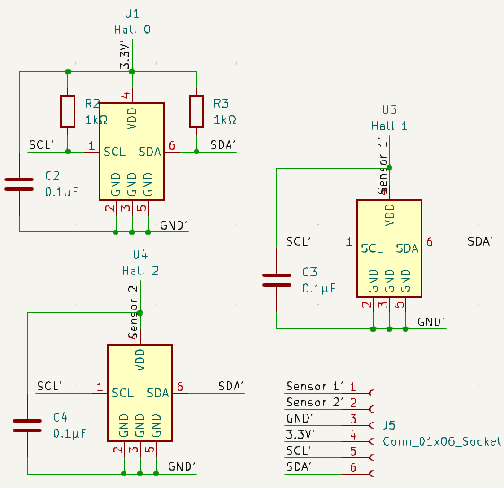
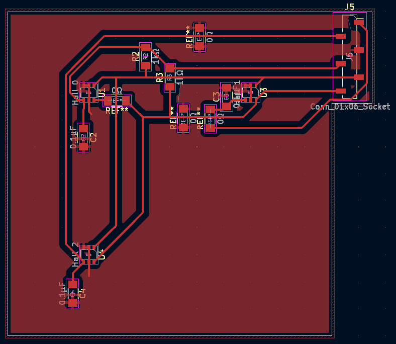
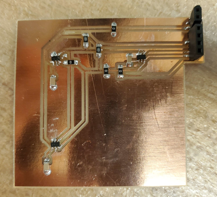
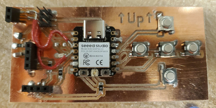
The Hall sensors are located at (-30, 30), (30, 30), (-30, -30) relative to the center of the board, all in millimeters. I was going to do an alignment, but figuring out the right size of hole to use was too hard so I just said whatever.
Welcome to Electronics 2: The Unreliable Ground
Alas, before I could program the position finding logic, a lot of problems happened:
- Display stopped working. Turns out that the connection between GND on the board and the GND copper came a little loose. That needed a re-solder.
- Board stopped working. 3.3V got shorted to GND in an annoying to remove way. The short was kind of deep into the board and needed a curved-end soldering iron to delete.
- Display still not working. Turns out that the connection between the GND copper and the relevant socket came loose. More re-soldering.
- Display not working when main board is connected to sensor board. In the TLE493D-A2B6 user manual §2.5, there’s a phenomenon where if you disconnect power to a sensor while communication is happening, it could make SCL and/or SDA stuck low. So I needed to power up all the sensors initially so that they release their GND pulls on SCL and SDA. And by the way, the reset code was wrong: it doesn’t use a sensor address, because how do you know which address to use?
This is the actual reset code:
Wire.requestFrom(0x7f, 0);
Wire.requestFrom(0x7f, 0);
Wire.beginTransmission(0x00);
Wire.endTransmission();
Wire.beginTransmission(0x00);
Wire.endTransmission();
delayMicroseconds(50);
(That’s how you do start, send 0xff, stop, start, send 0xff, stop, start, send 0x00, stop, start, send 0x00, stop, wait.)
After much debugging and looking things up in the references, I found a way to activate all 3 sensors:
- turn on all sensors and wait
- reset all sensors
- turn off sensor 1 and sensor 2 and wait
- configure sensor 0, including address
- turn on sensor 1 and wait
- configure sensor 1, including address
- turn on sensor 2 and wait
- configure sensor 2, including address
And there’s a parity bit which actually needs to be written manually or things won’t work. But finally, I got all 3 sensors working!
To get the position, I intersect directions taking the sensor offsets into account. Each pair of sensors gives a position, and that position gets weighted by how perpendicular the directions are (so that very finicky parallel direction intersections don’t have much influence). (Technically, they should also be weighted by the strength of the magnetic field, with a sweetspot getting the highest weight, but whatever). After adding some drawing code, here’s the result:
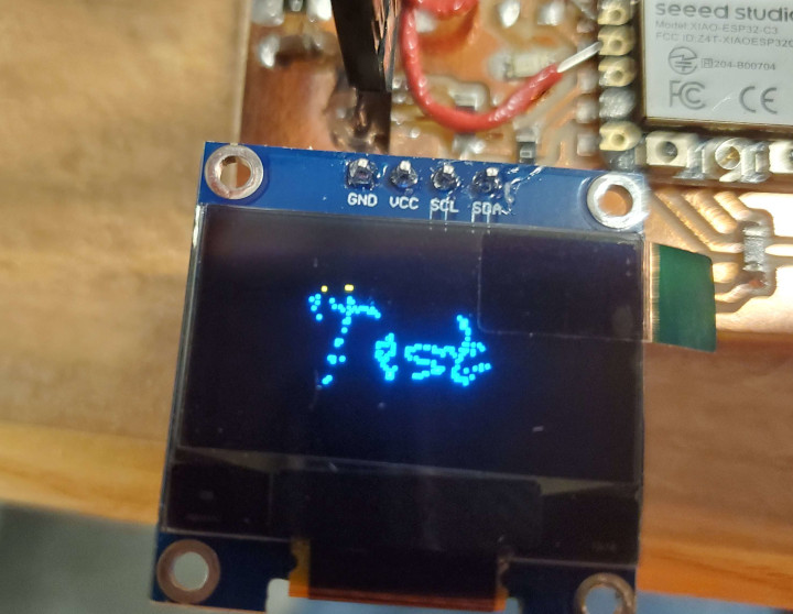
The code is below:
#include <Adafruit_SSD1306.h>
#include <Wire.h>
#include <BasicLinearAlgebra.h>

using Vec2 = BLA::Matrix<2, 1>;
using Mtx2 = BLA::Matrix<2, 2>;

enum Button {
  BTN_UP,
  BTN_DOWN,
  BTN_LEFT,
  BTN_RIGHT,
  BTN_ENTER
};
const int BUTTONS[] {10, 21, 8, 9, 20};
const int NUM_BUTTONS = sizeof(BUTTONS) / sizeof(int);

uint curr_time = 0;
uint mod_time = 0;

const int SCREEN_WIDTH = 128;
const int SCREEN_HEIGHT = 64;
const int SCREEN_ADDRESS = 0x3c;
Adafruit_SSD1306 display(SCREEN_WIDTH, SCREEN_HEIGHT, &Wire, -1);

const int HALL_1_POWER = 4;
const int HALL_2_POWER = 5;
const int HALL_DEFAULT_ADDRESS = 0x35;
const int HALL_ADDRESSES[] {0x22, 0x78, 0x44};
const int NUM_HALLS = 3;

// all lengths in mm
struct Hall {
  Hall(int address_, Vec2 offset_, float angle_) :
    address(address_), offset(offset_), angle(angle_) {}

  void calcDirection() {
    Wire.requestFrom(address, 6); // read 6, even though only up to 5 are needed (2D). Otherwise, the interface freezes.
    int bx, by, v4;
    bx = Wire.read();
    by = Wire.read();
    Wire.read();
    Wire.read();
    v4 = Wire.read();
    Wire.read();
    bx = (bx << 4 | v4 >> 4) << 20 >> 20;
    by = (by << 4 | (v4 & 0b1111)) << 20 >> 20;

    Vec2 b{bx, by};
    b /= BLA::Norm(b);
    direction = b;
    normal = Mtx2{0, 1, -1, 0} * b;
  }

  int address;
  Vec2 offset;
  float angle;
  Vec2 direction;
  Vec2 normal;
};

Hall halls[] {
  Hall(0x22, Vec2{-30,  30}, 0),
  Hall(0x78, Vec2{ 30,  30}, 0),
  Hall(0x44, Vec2{-30, -30}, 0),
};

void setupHallSensor() {
  pinMode(HALL_1_POWER, OUTPUT);
  pinMode(HALL_2_POWER, OUTPUT);
  digitalWrite(HALL_1_POWER, 1);
  digitalWrite(HALL_2_POWER, 1);
  delayMicroseconds(20); // in case they were low.

  // reset TLE493D
  Wire.requestFrom(0x7f, 0);
  Wire.requestFrom(0x7f, 0);
  Wire.beginTransmission(0x00);
  Wire.endTransmission();
  Wire.beginTransmission(0x00);
  Wire.endTransmission();
  delayMicroseconds(50);

  digitalWrite(HALL_1_POWER, 0);
  digitalWrite(HALL_2_POWER, 0);
  delayMicroseconds(20); // wait for power off

  for (int i = 0; i < NUM_HALLS; ++i) {

    // configure TLE493D
    Wire.beginTransmission(HALL_DEFAULT_ADDRESS);
    Wire.write(0x10);
    Wire.write(0x28);
      // config register 0x10
      // ADC trigger on read after register 0x05
      // short-range sensitivity
    Wire.write(0x15 | (i + 1) << 5 | (i + 1 < 3) << 7);
      // mode register 0x11
      // address depending on i. Parity bit set accordingly.
      // 1-byte read protocol
      // interrupt disabled
      // master controlled mode
    Wire.endTransmission();

    // Next!
    if (i == 0)
      digitalWrite(HALL_1_POWER, 1);
    else if (i == 1)
      digitalWrite(HALL_2_POWER, 1);
    delayMicroseconds(20); // enough time to power on the next Hall sensor (doc says max 10μs)
  }
}

void setup() {
  Serial.begin(115200);
  Wire.begin(6, 7);
  Wire.setClock(400000);

  setupHallSensor();

  Serial.println("Reached");

  if (!display.begin(SSD1306_SWITCHCAPVCC, SCREEN_ADDRESS)) {
    Serial.println("SSD1306 allocation failed");
    for (;;) {}
  }

  display.setTextSize(1);
  display.setTextColor(SSD1306_WHITE);
  display.clearDisplay();

  for (int i = 0; i < NUM_BUTTONS; ++i)
    pinMode(BUTTONS[i], INPUT_PULLUP);

  curr_time = micros();
}

void handleHallSensor() {
  if (!digitalRead(BUTTONS[BTN_ENTER]))
    display.clearDisplay();

  display.setCursor(0, 0);
  for (int i = 0; i < NUM_HALLS; ++i) {
    halls[i].calcDirection();
  }

  // Get positions
  Vec2 posSum{ 0, 0 };
  float weightSum = 0;
  for (int i = 0; i < NUM_HALLS; ++i)
    for (int j = i + 1; j < NUM_HALLS; ++j) {
      Mtx2 normalMtx{ halls[i].normal(0), halls[i].normal(1), halls[j].normal(0), halls[j].normal(1) };
      Vec2 dotVec{ (BLA::MatrixTranspose(halls[i].normal) * halls[i].offset)(0), (BLA::MatrixTranspose(halls[j].normal) * halls[j].offset)(0) };
      auto decomp = BLA::LUDecompose(normalMtx);
      Vec2 pos = BLA::LUSolve(decomp, dotVec);
      float weight = (BLA::MatrixTranspose(halls[i].normal) * halls[j].direction)(0); // the farther from 90°, the more shaky the measurement
      weight *= weight; // stay positive
      posSum += pos * weight;
      weightSum += weight;
    }

  Vec2 pos = posSum / weightSum;
  const Vec2 C{ 64, 32 };
  Vec2 offset = pos * 0.5f;
  if (!digitalRead(BUTTONS[BTN_UP]))
    display.writePixel(C(0) + offset(0), C(1) - offset(1), SSD1306_WHITE);

  Serial.printf("\n");
  display.display();
}

void loop() {
  uint diff = micros() - curr_time;
  curr_time += diff;

  handleHallSensor();
}