Architecture section is forever thankful to Kat (sp?) - she kindly found us on Thursday night when we were trying to brute force the group project assignment. After about an hour of work, we decided to divide and conquer via Google Docs :)
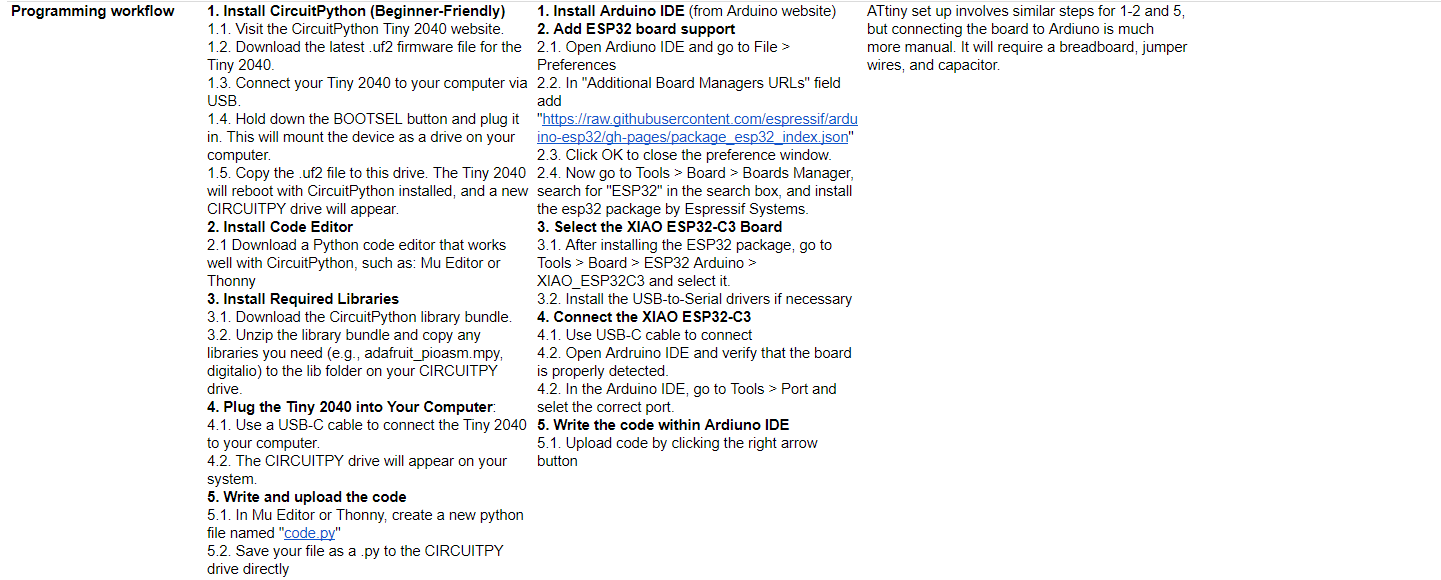
Before going to office hours, I didn't fully understand the difference between the board that a chip was on vs the chip (microcontroller) itself. Here is my first stab at the assignment before reviewing in office hours. I also didn't realize that Ardiuno can be used on all three.
I decided to take my notes in a matrix so that comparison was easier.
After going to office hours, I understood that the RP2040 for example was the "chip" and the Tiny2040 was just the board manufactured by Pimoroni which makes educational / entry level electronics. (They do have awesome marketing!)
I also learned that Ardiuno should work across all 4 chips, and upon Quentin's suggestion I also added the SAMD11C.
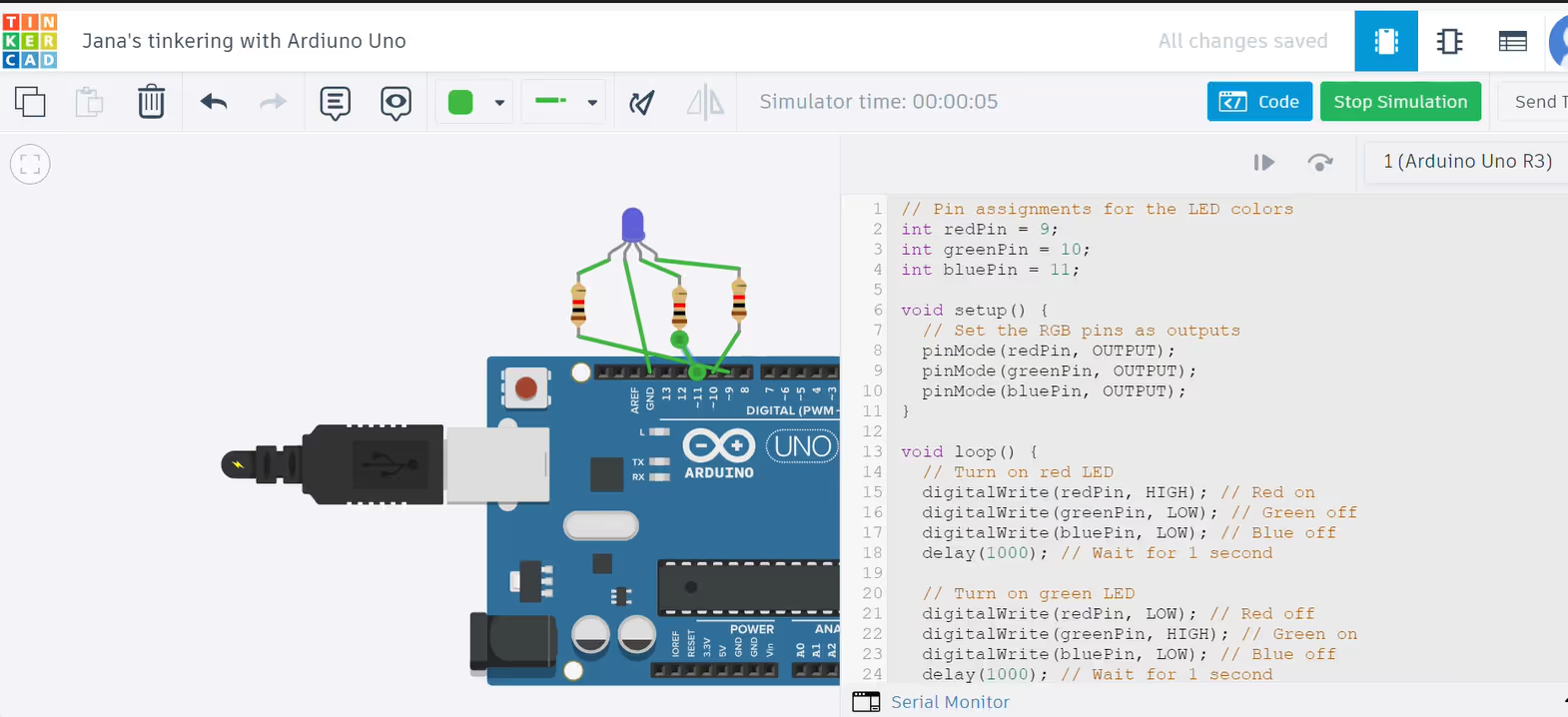
Initially, I used Tinkercad, but it didn't provide as much flexibility as Wokwi. Here's a screenshot of my work on Tinkercad before I moved to another simulator. I was easy to use the tutorial and ChatGPT to get the RGB LED to change colors. I also did a quick review of the Ardiuno Uno data sheet to better understand the pin assignments.
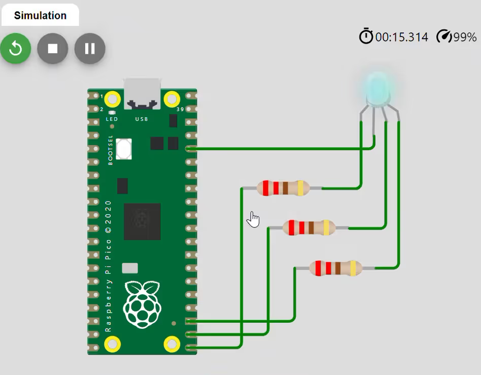
After playing with Tinkercad, I moved on to Wokwi where I could do more custom things with various controllers - like a Raspberry Pi Pico! Here is my code to get the light to fade different colors. I used a RGB LED.
// Define the pins for the RGB LED
#define RED_PIN 16
#define GREEN_PIN 17
#define BLUE_PIN 18
// Variables to store the PWM values for the RGB colors
int redValue = 0;
int greenValue = 0;
int blueValue = 0;
int fadeAmount = 10; // How much to fade the LED by
void setup() {
// Set up the RGB LED pins as outputs
pinMode(RED_PIN, OUTPUT);
pinMode(GREEN_PIN, OUTPUT);
pinMode(BLUE_PIN, OUTPUT);
}
void loop() {
// Fade from red to green
for (int i = 0; i <= 255; i += fadeAmount) {
redValue = 255 - i;
greenValue = i;
blueValue = 0;
setColor(redValue, greenValue, blueValue);
delay(50); // Delay to make the fading smooth
}
// Fade from green to blue
for (int i = 0; i <= 255; i += fadeAmount) {
redValue = 0;
greenValue = 255 - i;
blueValue = i;
setColor(redValue, greenValue, blueValue);
delay(50);
}
// Fade from blue to red
for (int i = 0; i <= 255; i += fadeAmount) {
redValue = i;
greenValue = 0;
blueValue = 255 - i;
setColor(redValue, greenValue, blueValue);
delay(50);
}
}
This seemed too easy - so I figured I would try to program an LED screen next with the RP 2040 Pico.
ChatGPT did provide the code!
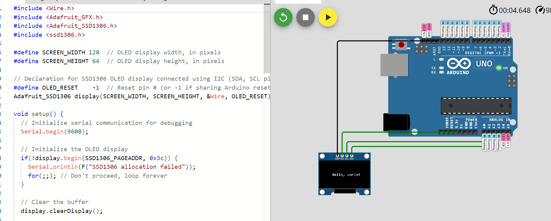
After TA office hours, I was encouraged to try something a bit more challenging. I took at stab at using the SSD1306 OLED with a Raspberry Pico.
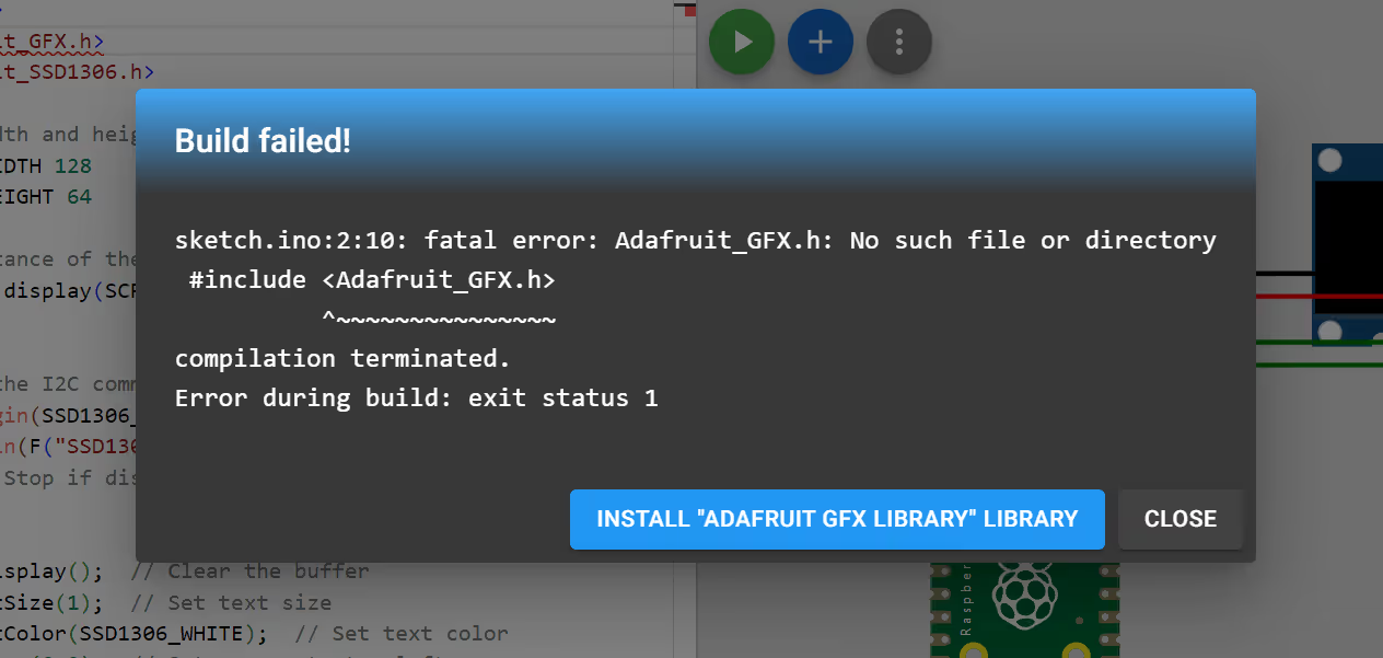
Initially, I didn't have my libraries installed. It was easy to add them in Wokwi.
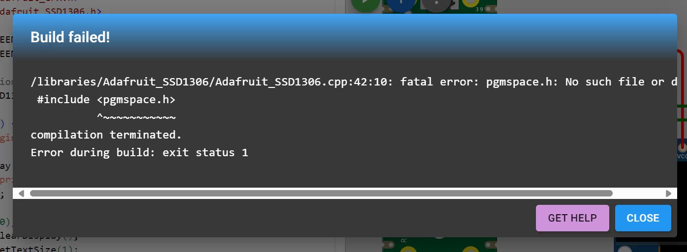
I then continued to get a pgmspace.h error... with lots of ChatGPT and internet searching, I eventually decided to try a new microcontroller.
My major takeaway here is ChatGPT can sometimes make it worse when you ask it to troubleshoot errors like this.
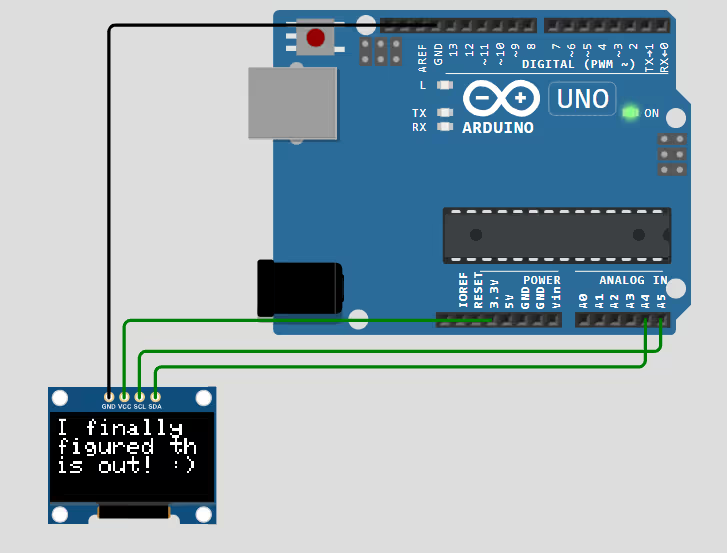
I tried to the ESP32 and then eventually the Arduino Uno. After about 30 minutes of trouble shooting with Anthony we were finally able to get it to work.
#include <Wire.h>
#include <Adafruit_GFX.h>
#include <Adafruit_SSD1306.h>
#include <ssd1306.h>
#define SCREEN_WIDTH 128 // OLED display width, in pixels
#define SCREEN_HEIGHT 64 // OLED display height, in pixels
// Declaration for SSD1306 OLED display connected using I2C (SDA, SCL pins)
#define OLED_RESET -1 // Reset pin # (or -1 if sharing Arduino reset pin)
Adafruit_SSD1306 display(SCREEN_WIDTH, SCREEN_HEIGHT, &Wire, OLED_RESET);
void setup() {
// Initialize serial communication for debugging
Serial.begin(9600);
// Initialize the OLED display
if(!display.begin(SSD1306_PAGEADDR, 0x3c)) {
Serial.println(F("SSD1306 allocation failed"));
for(;;); // Don't proceed, loop forever
}
// Clear the buffer
display.clearDisplay();
// Display a welcome message
display.setTextSize(1); // Normal 1:1 pixel scale
display.setTextColor(SSD1306_WHITE); // Draw white text
display.setCursor(30, 30); // Start at top-left corner
display.println(F("Hello, world!"));
display.display(); // Display the buffer
delay(2000); // Pause for 2 seconds
// Clear display and draw shapes
display.clearDisplay();
display.drawLine(0, 0, SCREEN_WIDTH, SCREEN_HEIGHT, SSD1306_WHITE);
display.drawLine(SCREEN_WIDTH, 0, 0, SCREEN_HEIGHT, SSD1306_WHITE);
display.display(); // Show the buffer on the screen
delay(2000);
}
void loop() {
// You can add more code here to update the display or show animations
display.clearDisplay();
// Display a welcome message
display.setTextSize(1); // Normal 1:1 pixel scale
display.setTextColor(SSD1306_WHITE); // Draw white text
display.setCursor(30, 30); // Start at top-left corner
display.println(F("I finally figured it out!"));
display.display(); // Display the buffer
delay(2000);
}
You can also watch it work here on Wokwi