Week 5: Make and test a microcontroller development board that you designed
This was actually... the most .... insane ... week so far. I've never been so close to the edge of madness! If you told me that milling my board was the EASY part on Friday afternoon. I would have laughed at you.... But by Monday night (Thank GOD for the long weekend) I was stressing... Learning to solder took a while. Lots of Youtube videos and I did slightly burn my left index finger. After several hours I started to get it.
One big learning for me this week was that I wish I used the multimeter sooner! I should be using it AS I solder NOT after the whole thing is done. And even though I went to the multimeter training last week, I really didn't understand how to use it until today (Tuesday Oct 15th) when Anthony showed me again, and we tested my board together. And then I soldered some more, and tested again, and now I love that freaking thing.
I really does take a few doing/hearing something before it sticks in your head.
Here's my journey below:
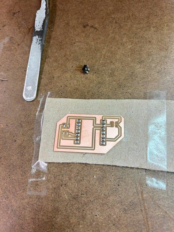
This was the second board that I printed out (the first I messed up the trace with and didn't think it would work)
You can see the that I added solder to all the pads (that's what I thought I needed to do at first)
This was also my neopixel board (which I realized later that neopixels were going to be really hard to chase down over the holiday weekend)

Then I got nervouse and thought I should test out a basic light to make sure I understood how the basics worked
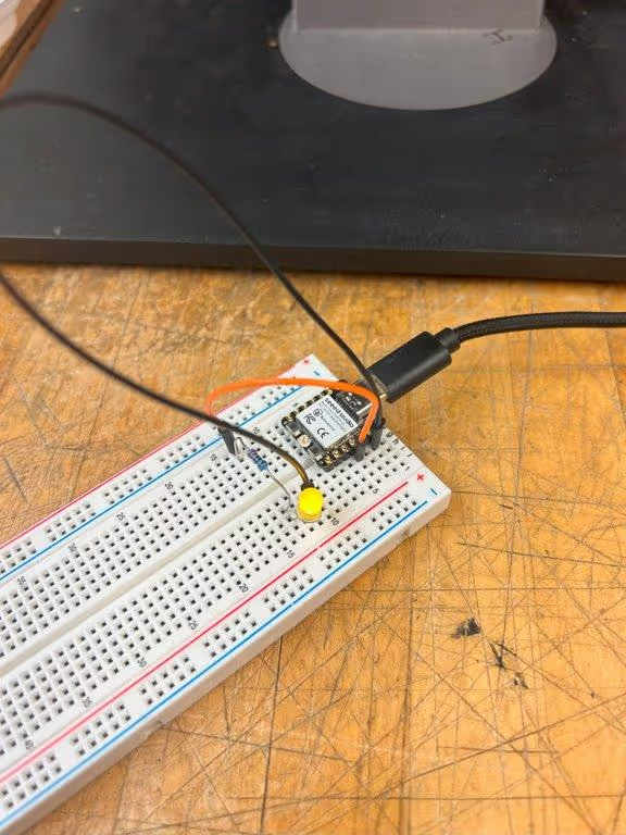
Here it is lit up!
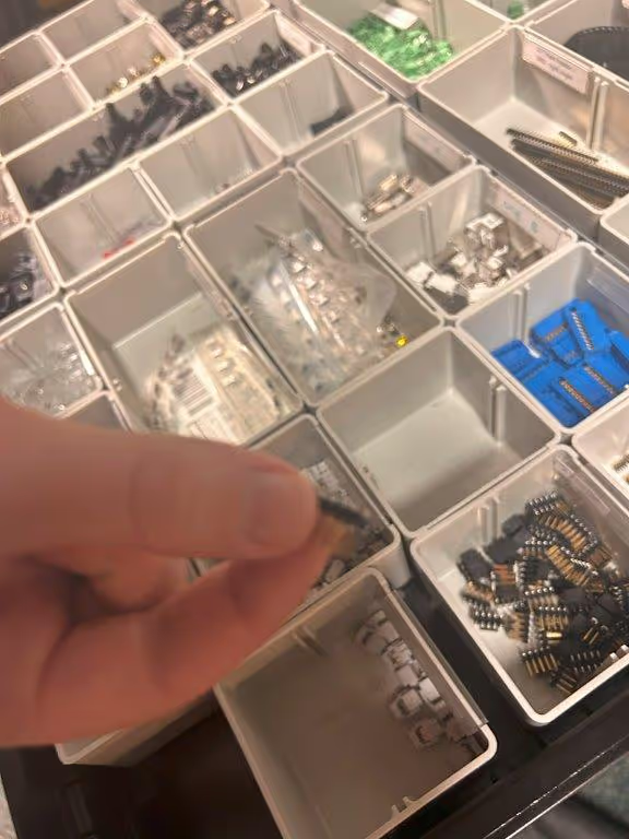
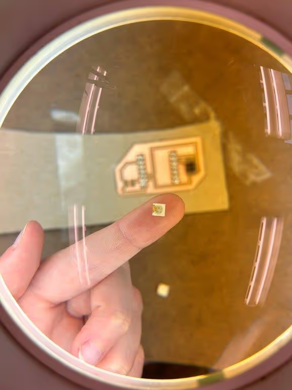
Monday afternoon, I chased down Miana to borrow a few neopixels. This is also when I realized that I had my footprint wrong.
So I decided to step back from the neopixel board and cut another board for a regular RBG LED.
Here I am solder my resistors in the wrong direction :) It was a disaster.... So I had to venture to the EECS lab on Tuesday morning for help.
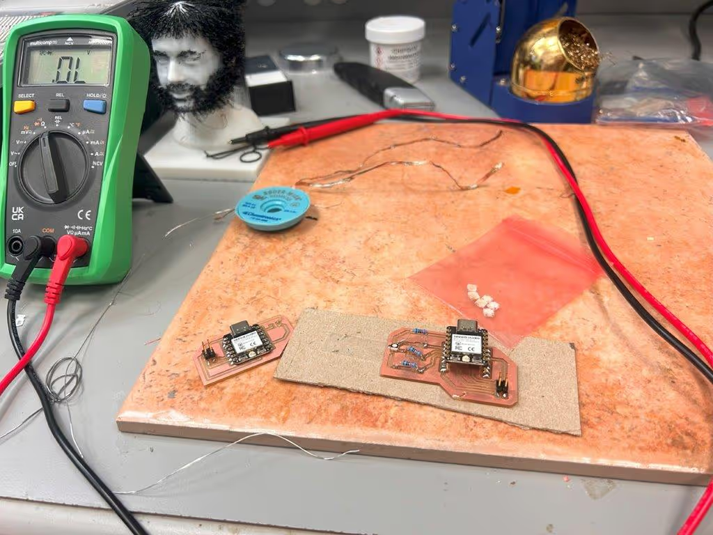
Here I am in EECS getting help ...
We figured out that my LED was oriented the wrong way and I had mistaken the LED for an cathode instead of anode. So we needed to rewire to the 3.3v pin.
We decided to drop the neopixel board for now.
After lots of help from Anthony - we got it working!
[In case these links break - please find the videos at the bottom]
Here is the code I used to get the pin to work:
// Define pin numbers
const int redPin = D1;   // D1
const int greenPin = D2; // D2
const int bluePin = D3;  // D3

void setup() {
  // Set pins as outputs
  pinMode(redPin, OUTPUT);
  pinMode(greenPin, OUTPUT);
  pinMode(bluePin, OUTPUT);
}
void loop() {
  // Cycle through colors
  setColor(255, 0, 0); // Red
  delay(1000);
  setColor(0, 255, 0); // Green
  delay(1000);
  setColor(0, 0, 255); // Blue
  delay(1000);
  setColor(255, 255, 0); // Yellow
  delay(1000);
  setColor(0, 255, 255); // Cyan
  delay(1000);
  setColor(255, 0, 255); // Magenta
  delay(1000);
  setColor(0, 0, 0); // Off
  delay(1000);
}
Week 5: Characterize the design rules for your in-house PCB production process (group)
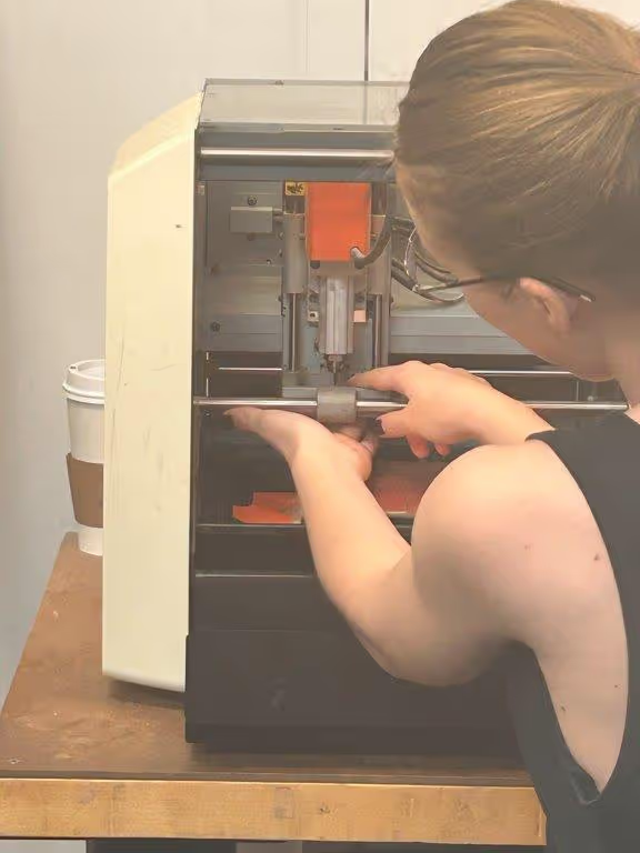
Learning the Roland in the Arch Lab:
- It was somewhat manual to adjust it
- You have to change the bit to the 1/64 mil (which is not a millimeter... mil is a thousands of an inch!)...
- Then after the traces are milled, you change the bit to 1/32 mil
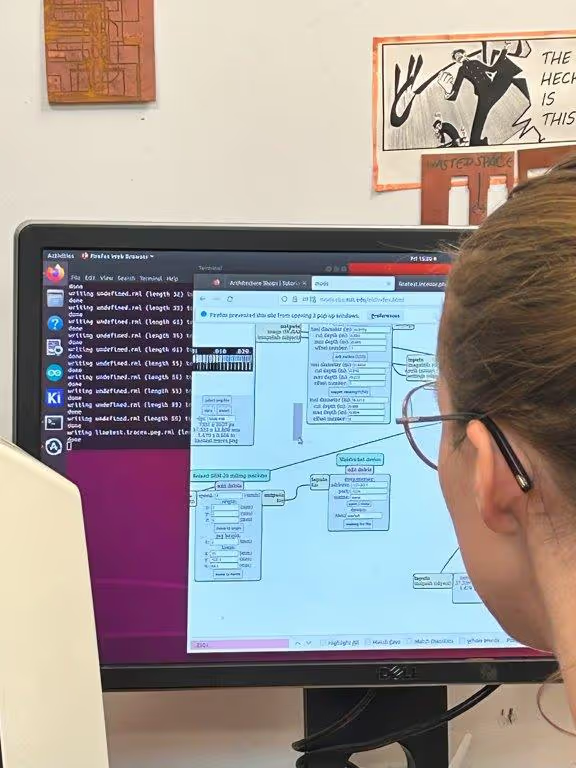
In mods, you upload your PNG (which was exported from Fusion), select if it's the trace or the outline (which I also didn't know needed to be exported separately), and then calculate.
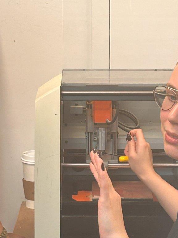
Then you bring the drill bit down to the board before sending the file to the device to begin milling.
The Roland can be a bit tempermental and if the green light starts blinking it means that the machine "errored out" and has to be restarted.
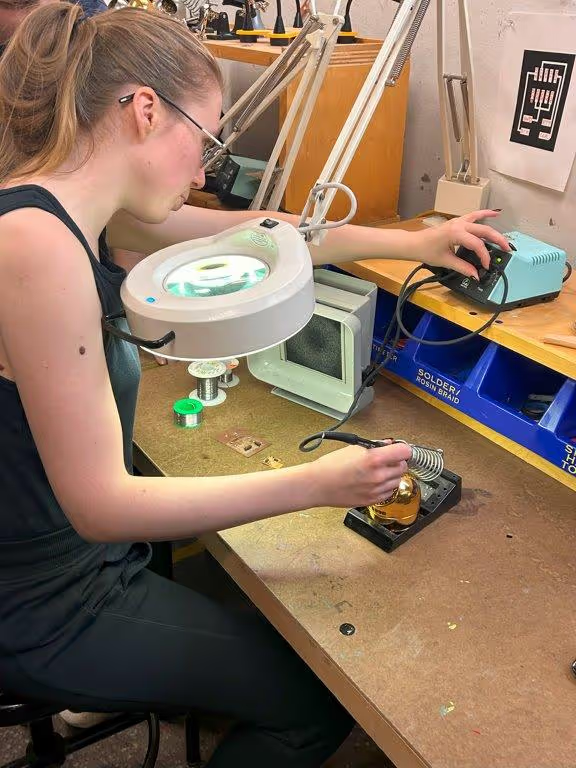
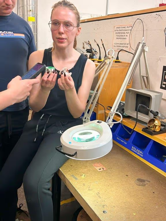
Here is Diana quickly showing us how to solder. It's easy to watch but hard to do in practice.
A few things I learned about soldering:
1. Heat the thing you are trying to solder before applying the solder. It's drawn toward the heat!
2. As mentioned already - check along the way if things are connecting properly with the multimeter
3. Only put one bead of solder down for a component and then come back on top with more solder on the un-soldered joins. My first round, I thought I had to put solder on every single pad before laying my components - NO - this was not the way to do it.
Video section: