Week 8: Output Devices
Add an output device to a microcontroller board you've designed, and program it to do something
This week was unexpected painful. Since I worked ahead in the last week by adding a neopixel strip to my microcontroller, I thought it would be a piece of cake to add a neopixel grid and an enclosure for the grid.
My original plan for this week was to create to separate boards: one that collected motion signal in a bracelet, and the other one which received the motion signals via wifi and then visualized it in an enclosed light display. So I set out to create 1) a bracelet with an enclosure for my ESP32-C3, MPU6050, and lipo battery, and 2) and enclosure for a 32x8 neopixel grid which would receive instructions via wifi.
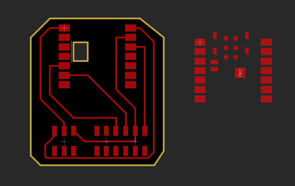
For the bracelet board, I wanted to see if I could add a battery. The XIAO ESP32-C3 has battery pads underneath, and so I cut a box where i could then wire the battery through the bottom. If you see to the right, there are the pads of an "untaped" ESP32-C3. I used that to reference as the rest would be taped for me.
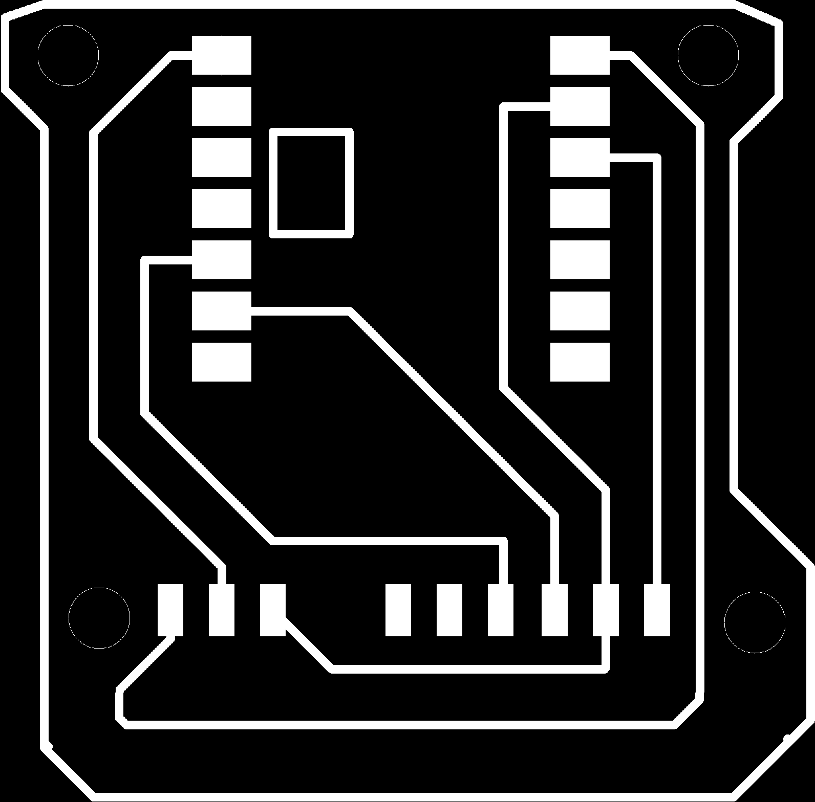
First cut out, but then I realized I didn't leave enough room for my MPU on the right side
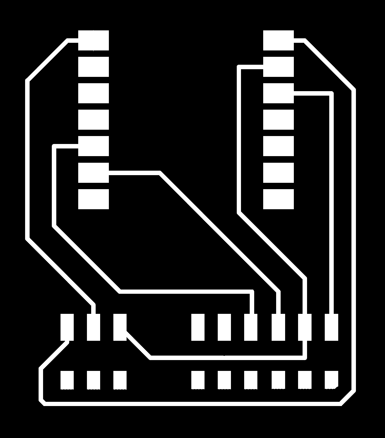
I left the unconnected pads on the bottom so there was more space for the MPU6050 to rest.
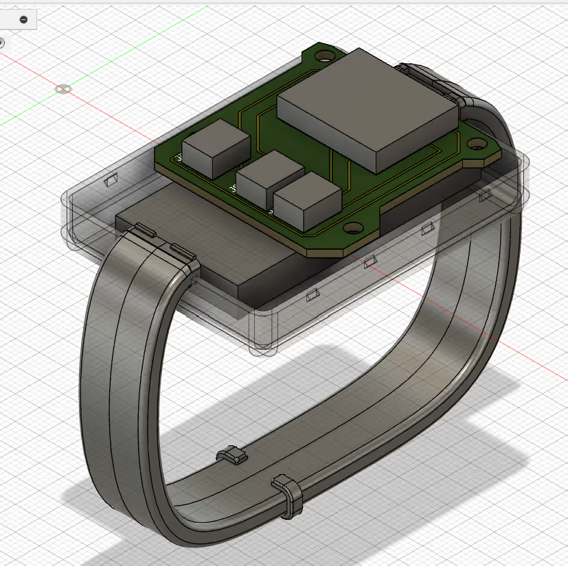
After designing the board and measuring the depth of the other components, I threw them into Fusion and designed the enclosure and attaching bracelet.
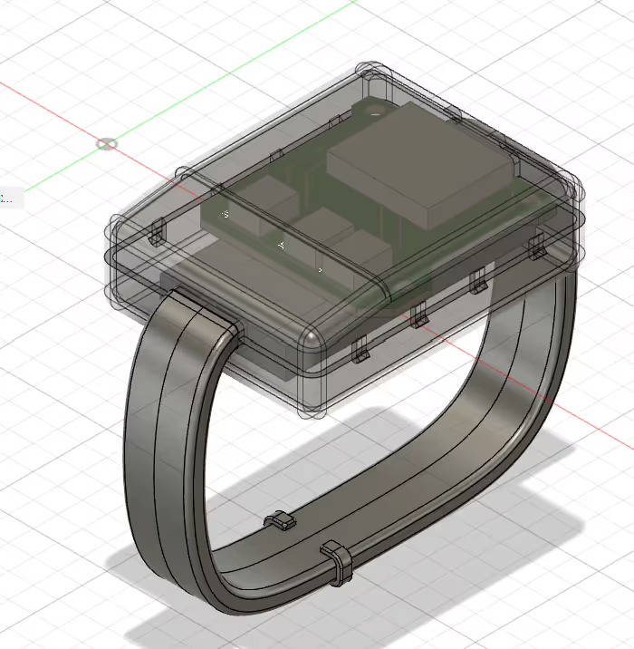
The strap of the bracelet was not designed well. For my final project, I will probably use fabric or some other material. I would like to have some light visualization on the arm as well as the separate light enclosure.
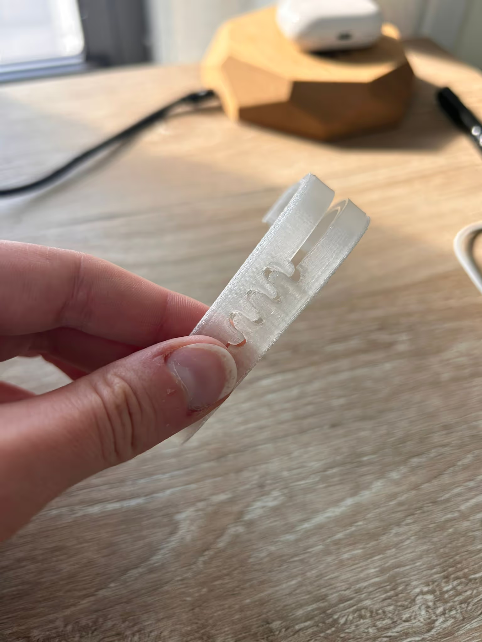
Before the screenshots to the left, I designed the strap to fit together in this zig zag. Which it also a design that doesn't make sense because it doesn't actually create a snap between the sides of the bracelet.
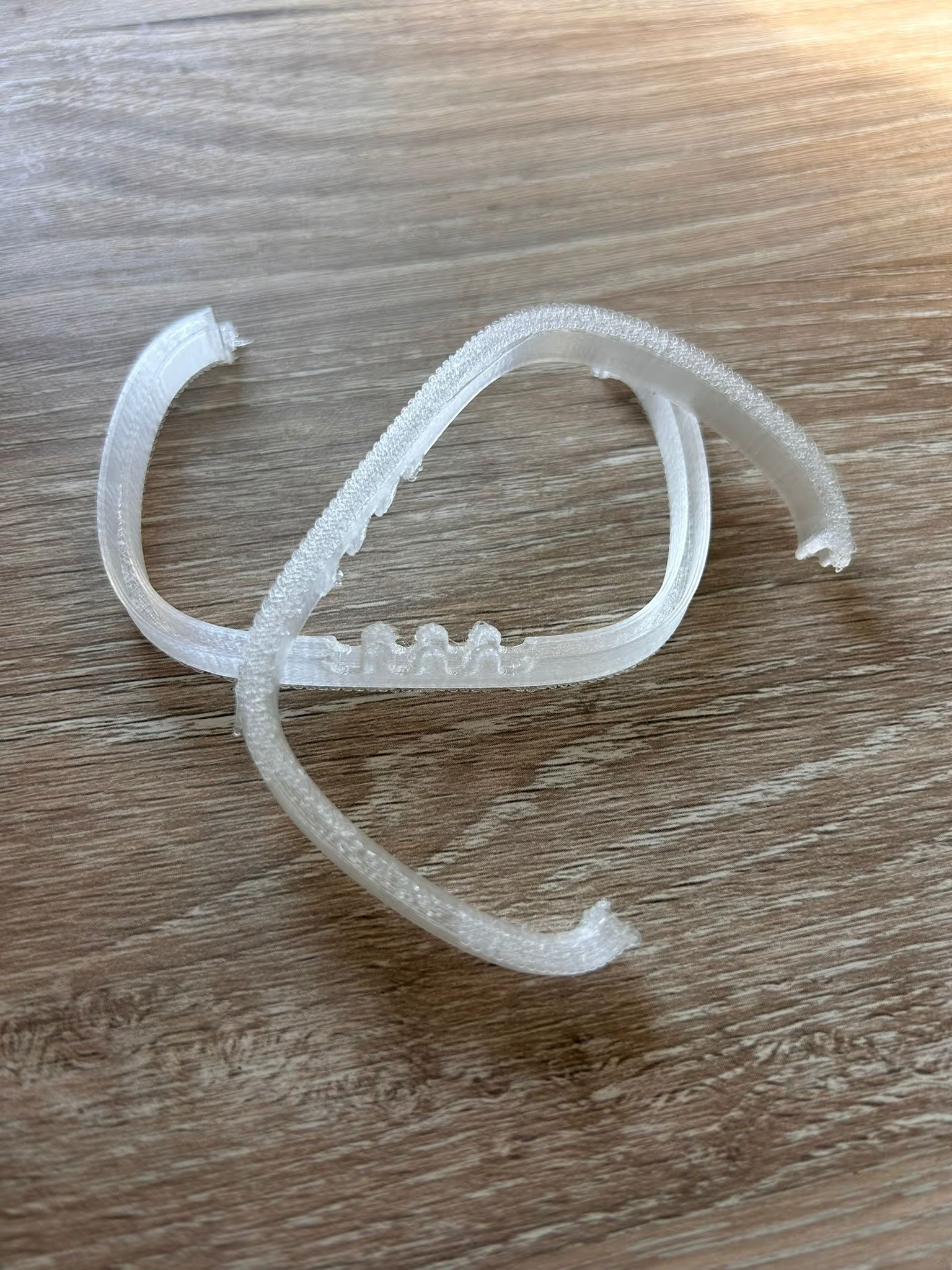
I used transparent TPU for this first print. The print didn't turn out well but I did like the TPU material - I hope to use it in my final project.
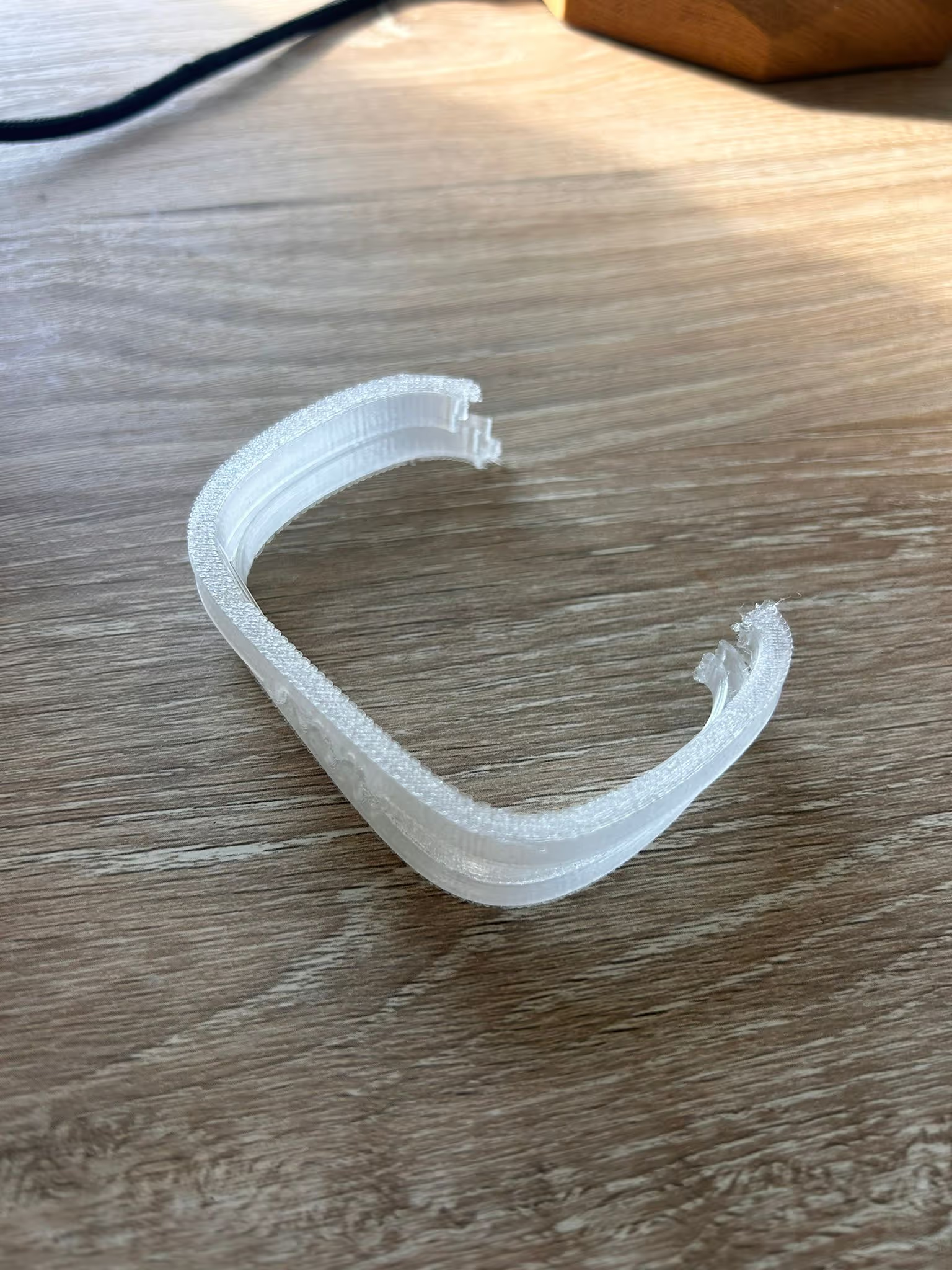
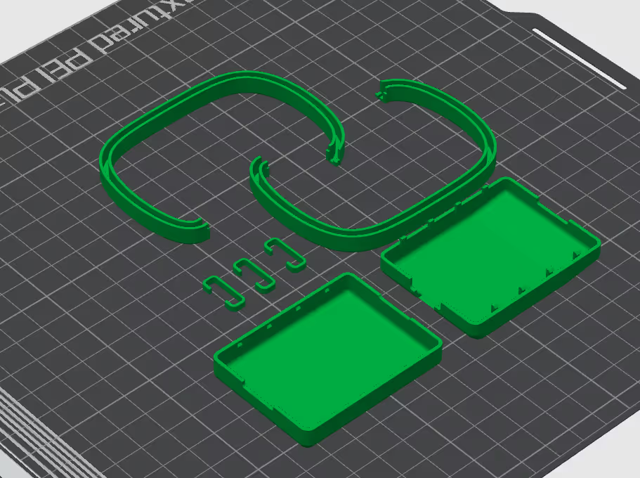
Screenshot of the print in Bambu. I printed it in generic PLA so that it would be less flimsy.
From last week, I knew that my original board could handle the string of 60 neopixels, but Alec/Anthony flagged that the grid of 256 pixels might be too much power for the xiao esp32-c3 too support. So I worked with Alec to test the strip and measure the power consumption.
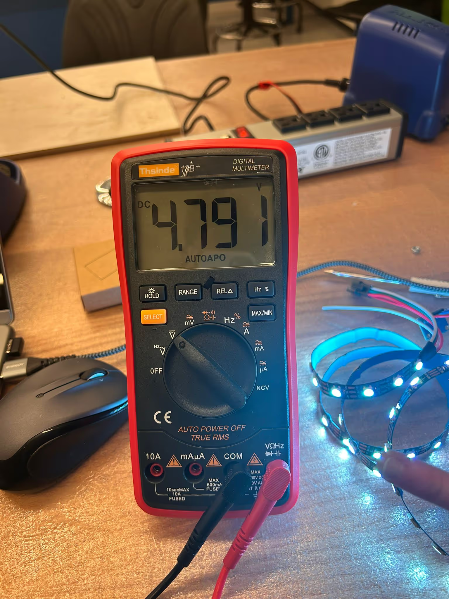
Voltage was about 4.8 (this is expected as the ws2812b datasheet specifies 5v and it is connected to the 5v pin on the ESP32-C3)
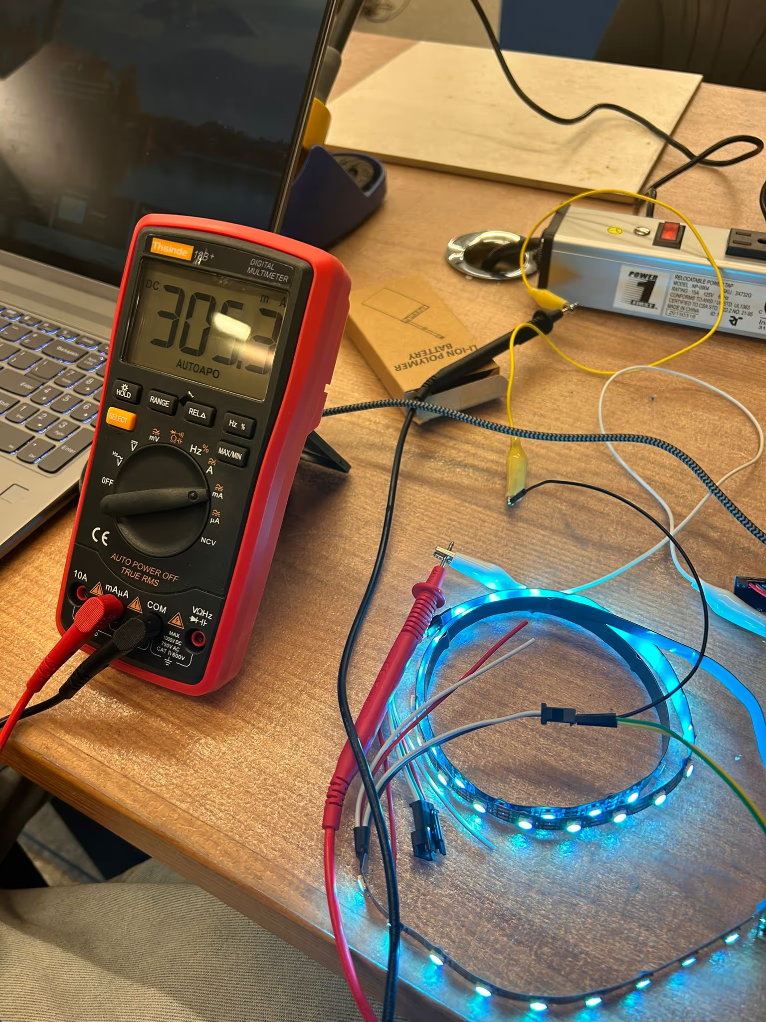
Amp ranged from 300 milliamps to 400 milliamps (not pictured)
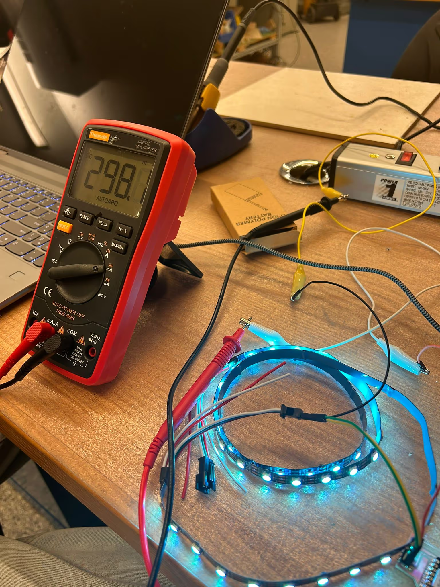
This is with the neopixels at full brightness. So to be safe we estimated the power consumption was 0.4 amps x 5v = 2 watts for 60 neopixels
Doing the math (assuming it's linear math)... 2 watts / 60 pixels = 0.03 watts/pixel
My grid had 256 pixels, so roughly that's 0.03 watts/pixel * 256 pixels = 8.5 watts total
Designing the physical enclosure for the neomatrix
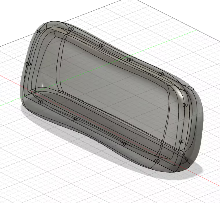
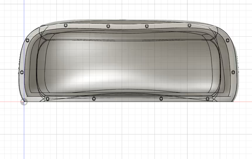
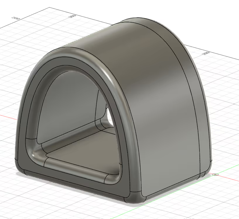
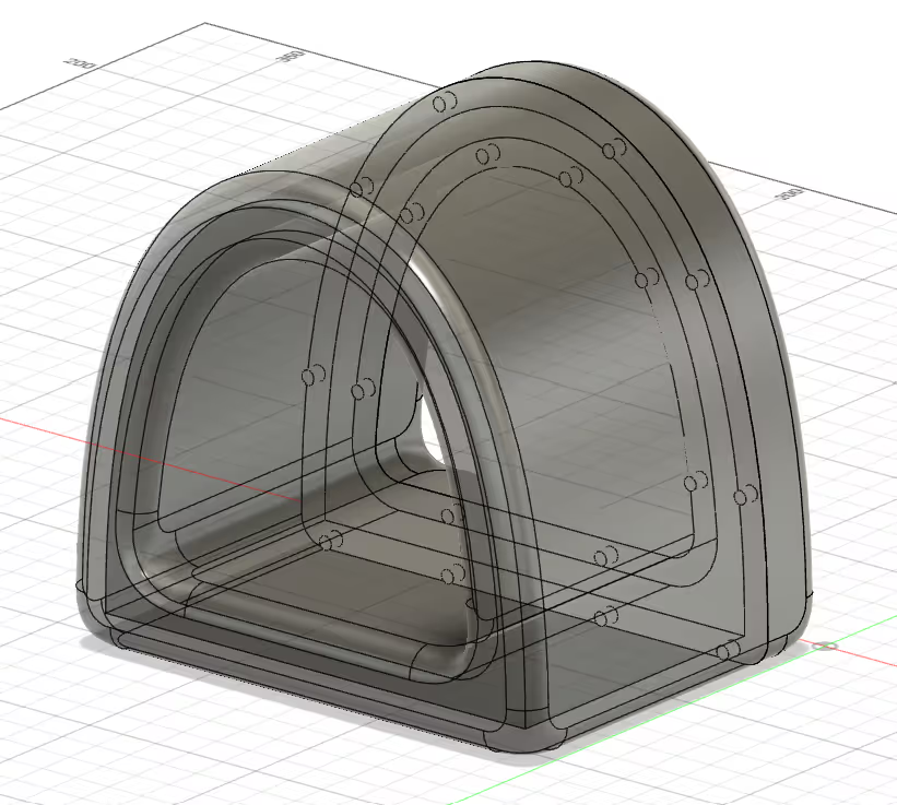
Since I had a massive grid of neopixels I wanted to use this week, I wanted to print an enclosure which would defuse the light nicely. My first design was too big for the printer so I opted for something that would allow me to fold the pixels into it.
But what I didn't expect to be the most difficult part was getting the neopixel grid to respond to my code. I quickly learned that the Adafruit Neopixel library in Arduino does not have code for a grid. After reading through several reddit and amazon review comments, I found a library that worked "Fast LED" and used that to activate the grid. The whole problem solving process for the code took almost 3 hours. It was so painful but I was glad to eventual solve it.
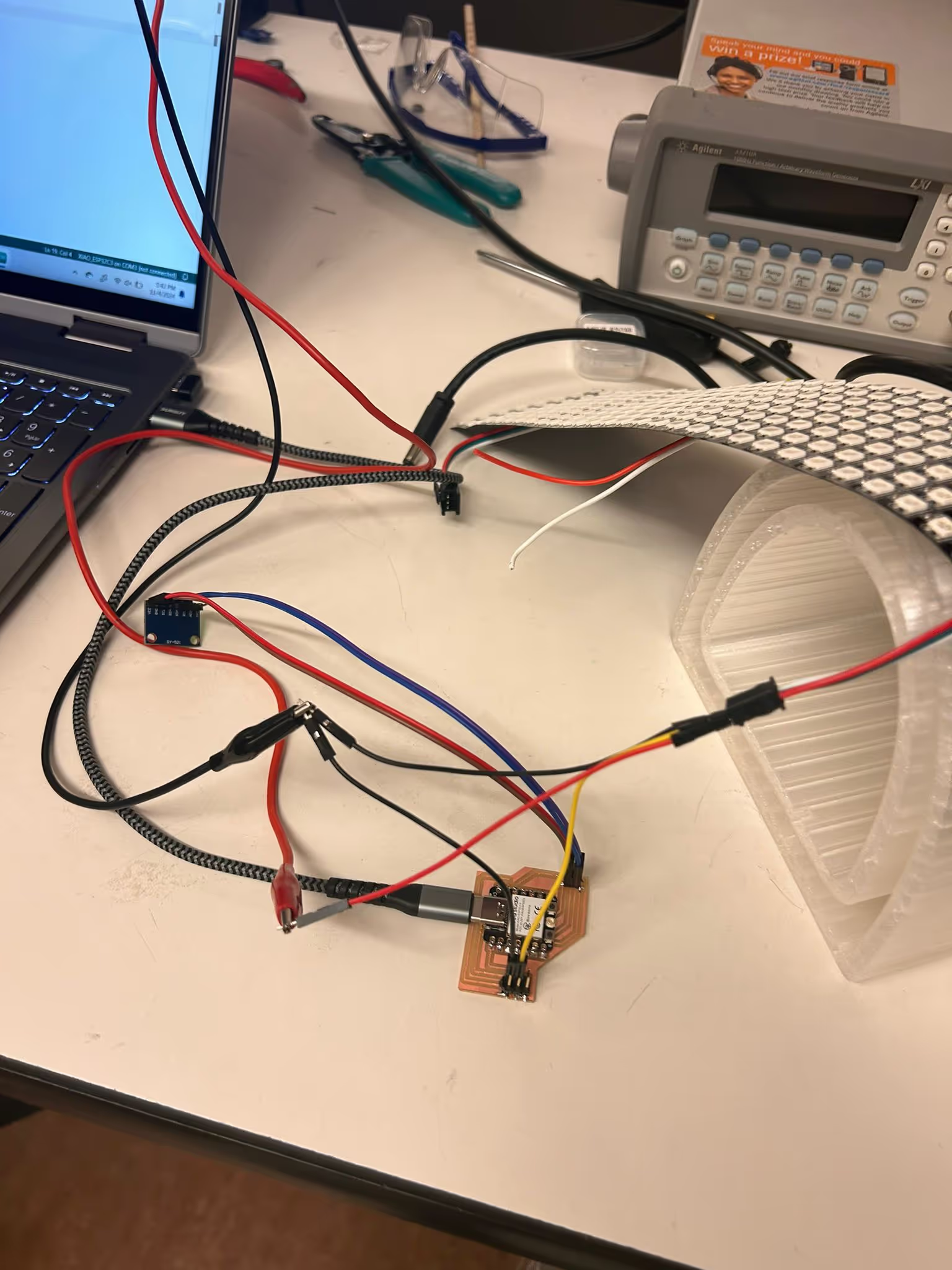
As mentioned earlier, we were not sure about the power consumption on the grid and hooked it up to a power supply.
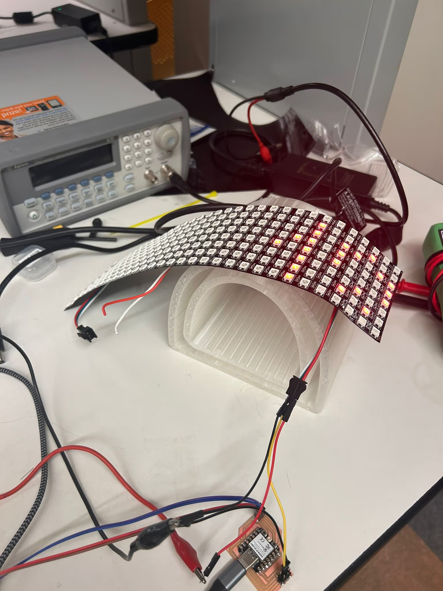
This is the part where I banging my head against the wall trying to figure out how to light the entire grid. I used examples directly from the Adafruit Arduino IDE library. A lot of them didn't work for me.
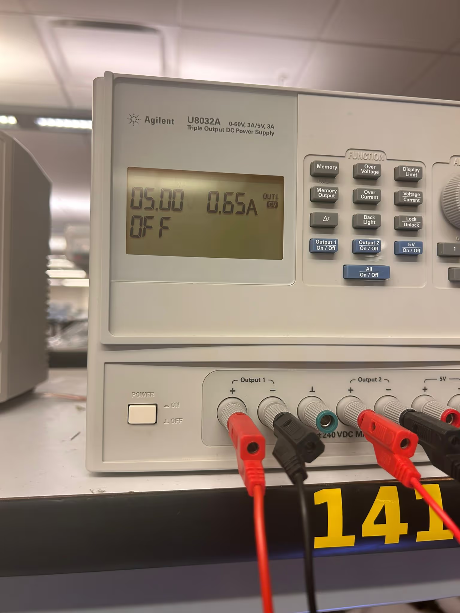
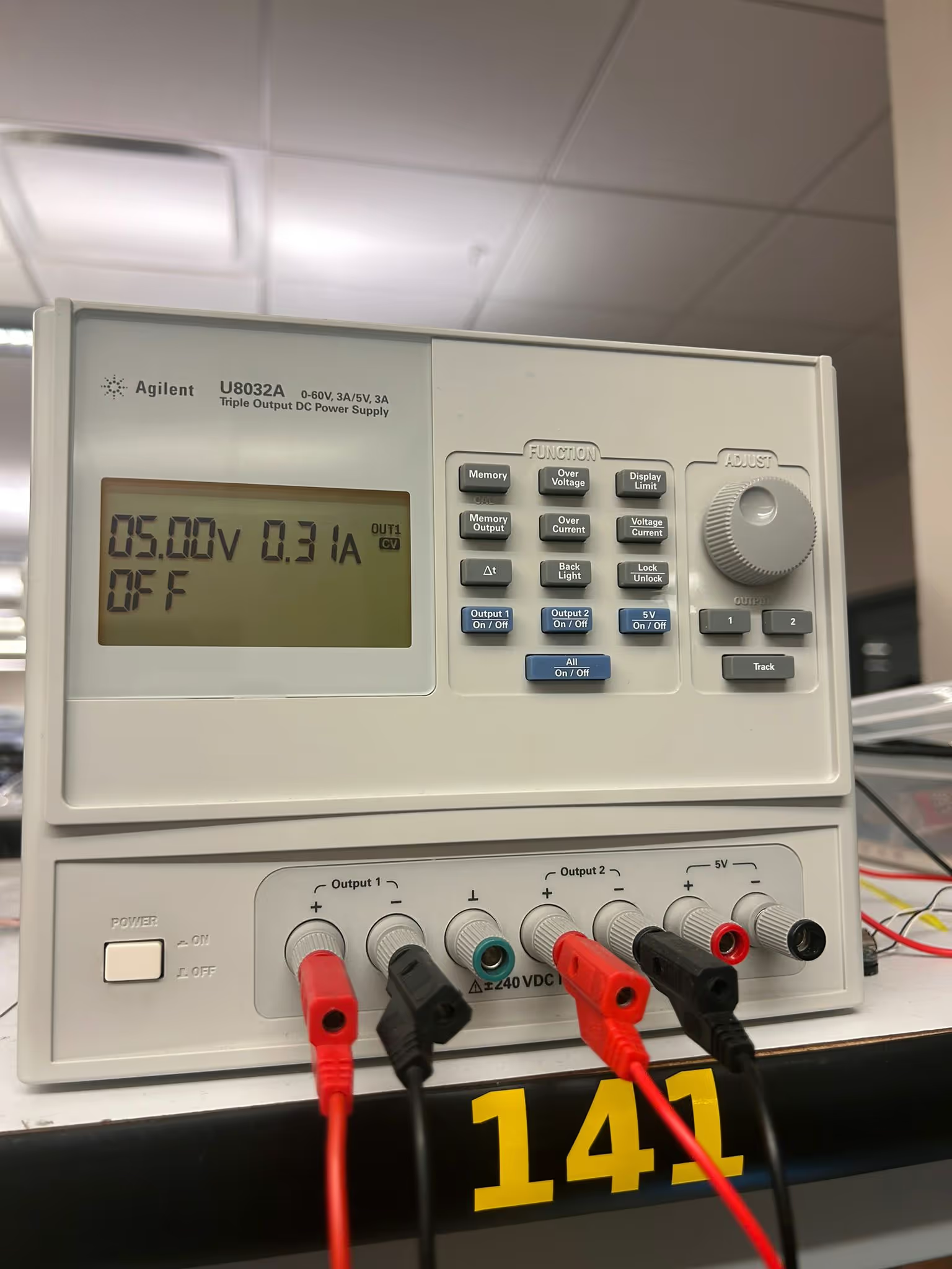
So I realize this isn't really the right way to measure power consumption, but you can see the pixel grid before and after I "dimmed" it in my code. It used half an amp less. This is great because I hated them at full brightness anyways, and they got way to hot.
The code that FINALLY WORKED
Here is the test code that finally light my entire grid.
#include <Adafruit_GFX.h>
#include <FastLED.h>
#define mw 8           // Matrix width
#define mh 32          // Matrix height
#define NUMMATRIX (mw * mh) // Total number of LEDs (256)

#define LED_PIN 2      // Update this to the correct data pin for the Xiao ESP32-C3

CRGB leds[NUMMATRIX];
void setup() {
    delay(1000);
    Serial.begin(115200);
    delay(1000);

    // Initialize FastLED with a single LED strip connected to LED_PIN
    FastLED.addLeds<NEOPIXEL, LED_PIN>(leds, NUMMATRIX);
    FastLED.setBrightness(32);   // Set initial brightness
    Serial.print("Matrix Size: ");
    Serial.print(mw);
    Serial.print(" x ");
    Serial.println(mh);
}
void loop() {
    // Light up all pixels sequentially in red
    for (int i = 0; i < NUMMATRIX; i++) {
        leds[i] = CRGB::Red;
        FastLED.show();
        delay(10);     // Adjust delay for speed of lighting up each pixel
    }
    delay(500);         // Hold the display for a moment

    // Clear the display
    FastLED.clear();
    FastLED.show();
    delay(500);         // Wait before repeating
}
Next here is the code after I updated it to visualize my movement of the MPU6050
#include <FastLED.h>
#include <Wire.h>
#include <MPU6050.h>
#define mw 8                  // Matrix width
#define mh 32                 // Matrix height
#define NUMMATRIX (mw * mh)   // Total number of LEDs (256)
#define DATA_PIN 2            // GPIO pin connected to NeoPixel data line

CRGB leds[NUMMATRIX];
MPU6050 mpu;
void setup() {
  Serial.begin(115200);       // Begin serial communication for debugging
  Wire.begin();               // Begin I2C communication for MPU6050

  // Initialize FastLED for the matrix
  FastLED.addLeds<NEOPIXEL, DATA_PIN>(leds, NUMMATRIX);
  FastLED.setBrightness(10);  // Set a lower brightness (try values between 5 and 20)

  mpu.initialize();           // Initialize the MPU6050
  if (!mpu.testConnection()) {
    Serial.println("MPU6050 connection failed");  // Debug if connection fails
    while (1);               // Halt if connection fails
  }
}
void loop() {
  int16_t ax, ay, az;
  mpu.getAcceleration(&ax, &ay, &az);  // Get accelerometer values

  // Map acceleration values to RGB colors
  int colorX = map(ax, -17000, 17000, 0, 255);  // Forward-backward
  int colorY = map(ay, -17000, 17000, 0, 255);  // Left-right
  int colorZ = map(az, -17000, 17000, 0, 255);  // Up-down

  // Update the matrix with the new color based on MPU6050 values
  setColor(colorX, colorY, colorZ);
  delay(100);  // Delay for time between sensor reads
}
// Function to set the color of all LEDs on the matrix
void setColor(uint8_t r, uint8_t g, uint8_t b) {
  for (int i = 0; i < NUMMATRIX; i++) {
    leds[i] = CRGB(r, g, b);  // Set each pixel to the specified color
  }
  FastLED.show();             // Push the color update to the matrix
}
the code that DID NOT WORK (don't use this, really)
#include <Adafruit_NeoPixel.h>
#include <Wire.h>
#include <MPU6050.h>
#define MATRIX_WIDTH 32      // Width of the NeoPixel matrix
#define MATRIX_HEIGHT 8      // Height of the NeoPixel matrix
#define NUM_PIXELS 256       // Total number of pixels in the 32x8 matrix
#define DATA_PIN 2           // GPIO pin connected to NeoPixel data line

Adafruit_NeoPixel pixels(NUM_PIXELS, DATA_PIN, NEO_GRB + NEO_KHZ800);
MPU6050 mpu;
void setup() {
  Serial.begin(115200);      // Begin serial communication for debugging
  pixels.begin();            // Initialize the NeoPixel matrix
  pixels.show();             // Turn off all pixels initially
  Wire.begin();              // Begin I2C communication for MPU6050

  mpu.initialize();          // Initialize the MPU6050
  if (!mpu.testConnection()) {
    Serial.println("MPU6050 connection failed"); // Debug in case of issues
    while (1);               // Halt if connection fails
  }
}
void loop() {
  int16_t ax, ay, az;
  mpu.getAcceleration(&ax, &ay, &az); // Get accelerometer values

  // Map acceleration to RGB values
  int colorX = map(ax, -17000, 17000, 0, 255);  // Forward-backward
  int colorY = map(ay, -17000, 17000, 0, 255);  // Left-right
  int colorZ = map(az, -17000, 17000, 0, 255);  // Up-down

  // Update the NeoPixel matrix with the mapped color
  setColor(colorX, colorY, colorZ);
  delay(100);  // Delay to allow time between sensor reads
}
// Function to set all pixels in the matrix to a specific color
void setColor(uint8_t r, uint8_t g, uint8_t b) {
  for (int y = 0; y < MATRIX_HEIGHT; y++) {
    for (int x = 0; x < MATRIX_WIDTH; x++) {
      int pixelIndex = getPixelIndex(x, y);
      pixels.setPixelColor(pixelIndex, pixels.Color(r, g, b));
    }
  }
  pixels.show(); // Push the color to the matrix
}
// Function to calculate the 1D index for a given (x, y) position in the matrix
int getPixelIndex(int x, int y) {
  if (y % 2 == 0) {
    // For even rows, go left to right
    return y * MATRIX_WIDTH + x;
  } else {
    // For odd rows, go right to left
    return y * MATRIX_WIDTH + (MATRIX_WIDTH - 1 - x);
  }
}