Update
I ended up figuring out the mic connections in networking week. I ended up using the Adafruit I2S Mems mic breakout board instead, and got that working. I didn't need any components other than my microcontroller (XIAO-ESP32S3) and the breakout board, so rather than designing a PCB, I used connecters and jumper wires. I found that this was a really good way to test quickly for the week, but will defniitely design a PCB and proper casing for the final project. You can check that out here!
Week 8 progress
This week, I accomplished half of the individual assignment in that I was able to add a sensor to a microcontroller board I designed, but failed in reading anything. For my final project, I've settled on the idea of making the magic mirror from Snow White, so for this week, I wanted to use a Xiao ESP32S3 microcontroller and read mic input device, the goal being to send audio to cloud to do speech processing. I designed a basic board with my microcontroller and the IC-4343 I2S mic, but struggled for a number of reasons. Thus, a lot of my documentation this week is of non-successes and frustrations.
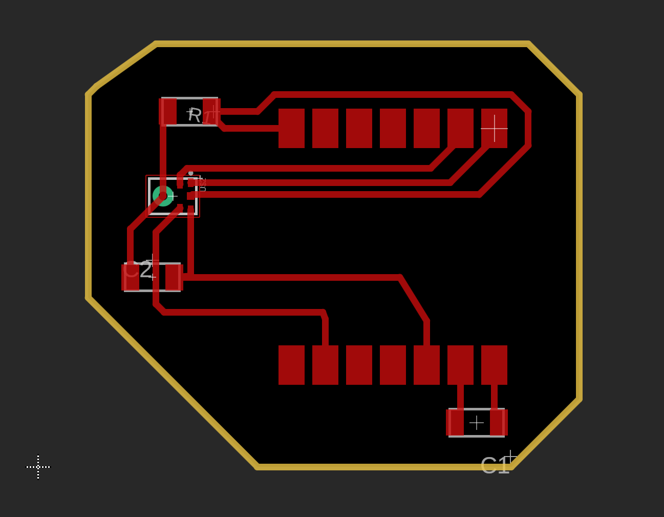
To start, here are my PCB design and schematic. My components were a Xiao ESP32S3, two bypass capacitors, the IC 4343 mic, and a 100k ohm resistor. As the datasheets instructed, I connected the mic pins to corresponding ESP32 pins (I2S on all pins) and ran the SD pin connection through the resistor. I also added the bypass capacitors for the mic and the microcontroller. See if you can spot here what I theorize as one of my mistakes...

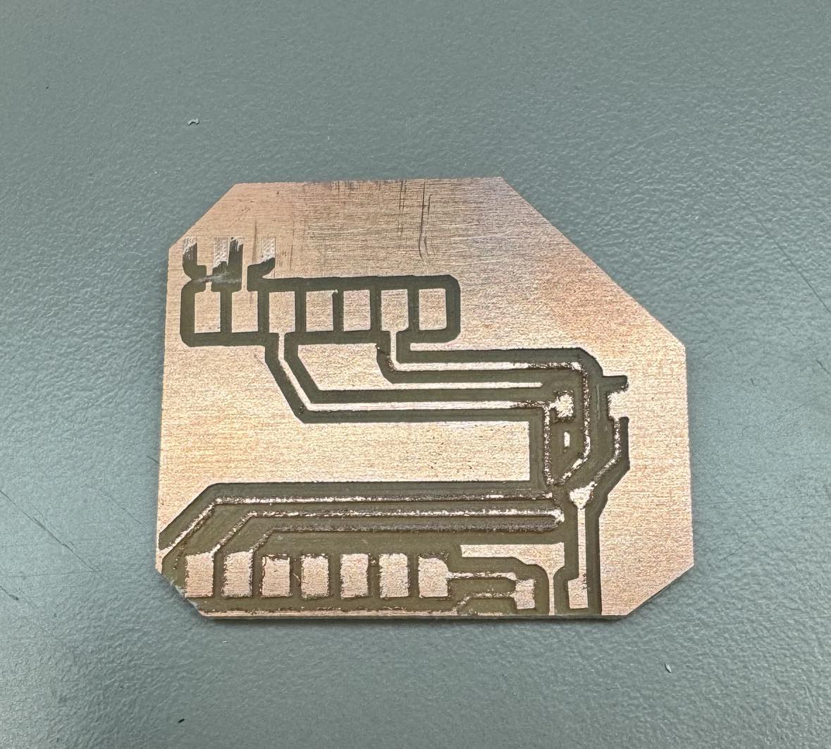
Next began a very painfully long process of cutting the PCB. Since I had previously used the Roland SRM-20 and the OtherMill was very busy in the EECS lab, I decided to use the SRM-20 again. Except, I had forgotten many of the details from when I first used it with Anthony, so I made many avoidable mistakes... Though now I feel very very confident that I can use it correctly now much more consistently. See exhibit one of using the wrong gerber-to-img site and not locking dimensions/location of converted pngs...
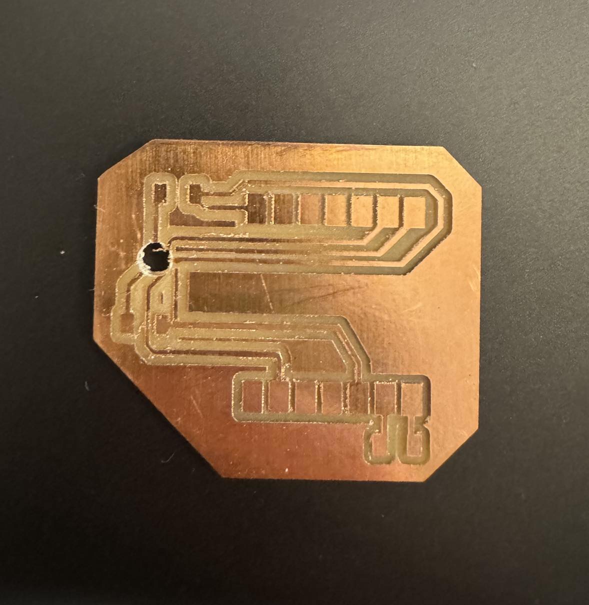
Exhibit two of locking images correctly but forgetting to invert the image for cutting the bottom port and so destroying the pads for the already tiny mic.
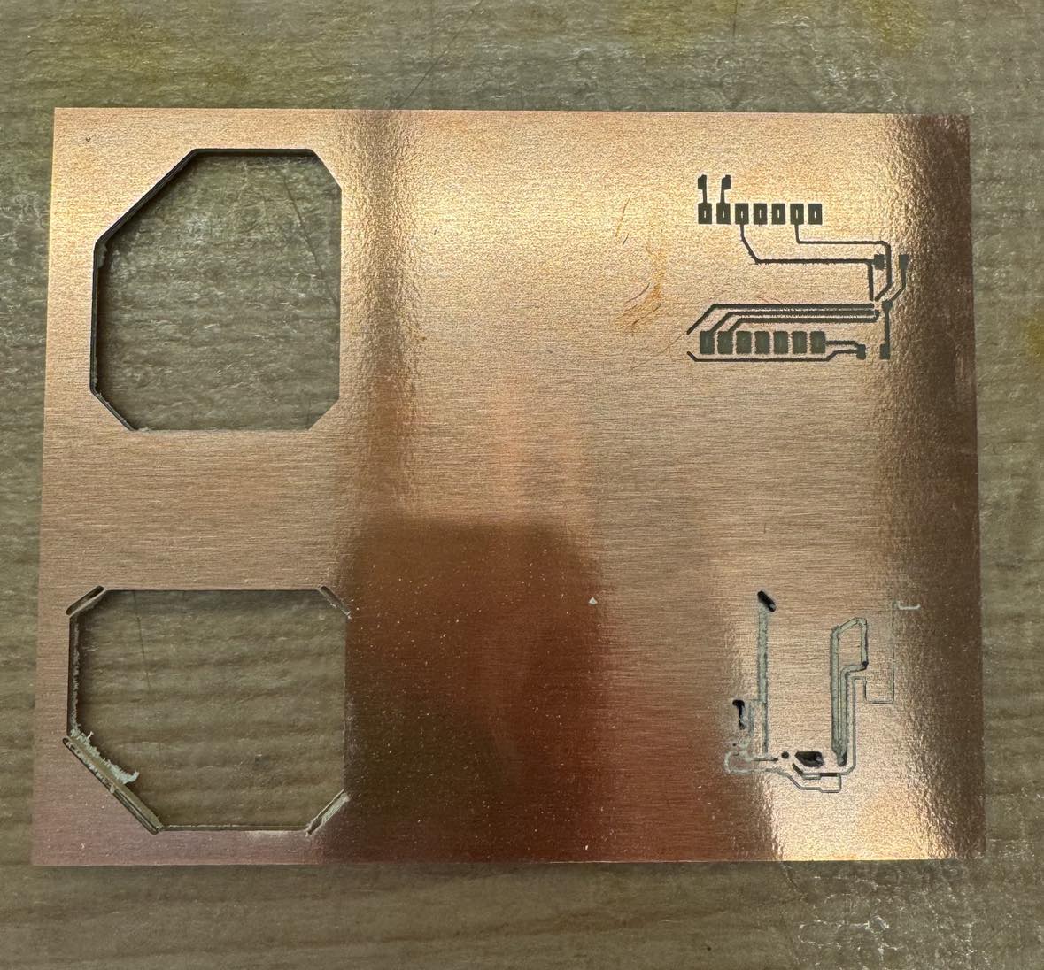
And exhibit 3, of 4 incorrectly cut boards- for the other two not yet mentioned, One I didn't invert, so instead of cutting traces it engraved the design, and the other I had the settings incorrectly so it was cutting too deep for the traces.
Very luckily (almost surprisingly), no end-mills were broken in this process.
I finally managed to cut a correct pcb based on my design and soldered on all the components. As you might imagine, I was now much over the time I had budgeted with my supply-side time management since I didn't anticipate the pcb cutting to take 3 times as long.
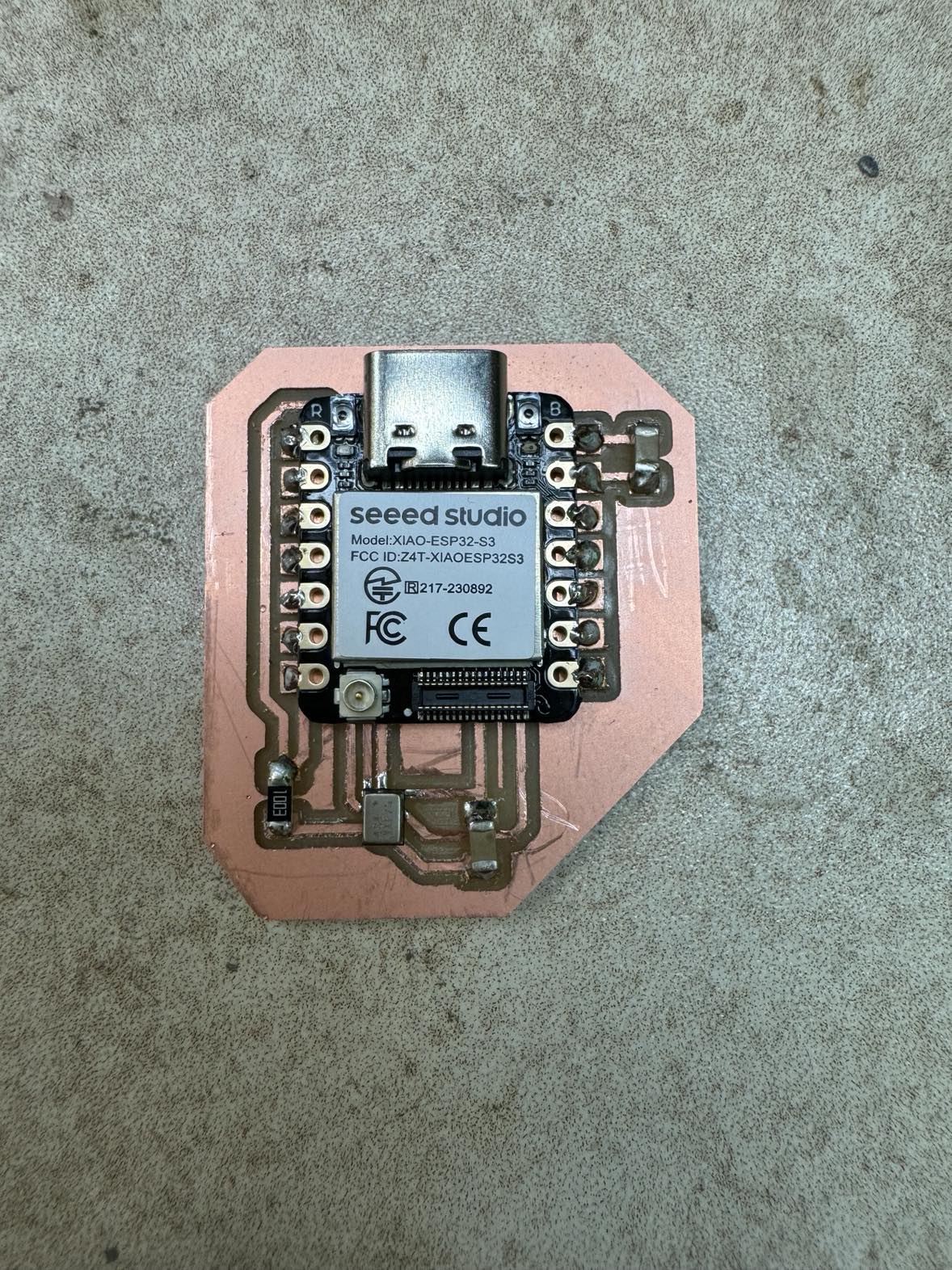
At this point, I started testing my connections. Everything seemed soldered correctly, even the tiny mic, which Alec from the EECS lab helped me out with (using solder paste and hot air gun). I started running into more problems when I plugged the ESP32 into power. While the power LED would turn on, it would turn off after about 1 minute, with nothing prompting it. Pressing the boot and reset buttons also did nothing, but if I unplugged it and plugged it back in, the LED would light up and then turn off in a minute again. I googled the issues but they all seemed to do with power source, which shouldn't have been an issue since the previous board I had also with a Xiao ESP32 had no issues staying powered. Just in case, I tried with a different USB-C cable but the same thing happened. I tried uploading code I found on the internet (like a Hello world for an ESP32S3 and I2S mic), which gave me many errors with connecting to the board (No Serial Data received). It did seem to upload once, printing zeros for the mic readings, but I wasn't able to replicate it and the microcontroller kept randomly powering off. Eventually, I took a look at my schematic again and realized that my GND pin on the mic was not actually connected to the GND pin on the microcontroller... Which would make sense for why power was finnicky and the mic was not working. At this point, I had run out of time for the week, and so am meekly writing my documentation knowing I might get reprimanded in class if I get called on... But planning on taking Thursday to figure this out by cutting a new PCB with the GND connection and adding connectors so I can use that board for output devices as well.
    #include

    #define I2S_WS 1
    #define I2S_SD 43
    #define I2S_SCK 7

    #define I2S_PORT I2S_NUM_0

    void setup() {
        Serial.begin(115200);
        Serial.println("Setup I2S ...");

        delay(1000);
        i2s_install();
        i2s_setpin();
        i2s_start(I2S_PORT);
        delay(500);
    }

    void loop() {
        int32_t sample = 0;
        size_t bytes_read;

        if (i2s_read(I2S_PORT, &sample, sizeof(sample), &bytes_read, portMAX_DELAY) == ESP_OK && bytes_read > 0) {
            Serial.println(sample);
        }
    }

    void i2s_install() {
        i2s_config_t i2s_config = {
            .mode = (i2s_mode_t)(I2S_MODE_MASTER | I2S_MODE_RX),
            .sample_rate = 44100,
            .bits_per_sample = I2S_BITS_PER_SAMPLE_16BIT,
            .channel_format = I2S_CHANNEL_FMT_ONLY_LEFT,
            .communication_format = (i2s_comm_format_t)(I2S_COMM_FORMAT_I2S | I2S_COMM_FORMAT_I2S_MSB),
            .intr_alloc_flags = ESP_INTR_FLAG_LEVEL1, // Recommended interrupt priority
            .dma_buf_count = 8,
            .dma_buf_len = 64,
            .use_apll = false,
            .tx_desc_auto_clear = true  // Ensures TX buffer is cleared on underflow
        };

        i2s_driver_install(I2S_PORT, &i2s_config, 0, NULL);
    }

    void i2s_setpin() {
        i2s_pin_config_t pin_config = {
            .bck_io_num = I2S_SCK,
            .ws_io_num = I2S_WS,
            .data_out_num = I2S_PIN_NO_CHANGE, // No output, only RX
            .data_in_num = I2S_SD
        };

        i2s_set_pin(I2S_PORT, &pin_config);
}