                        #include "pico/stdlib.h"

                        //Traffic light 1
                        #define RED_T1 3
                        #define YELLOW_T1 4
                        #define GREEN_T1 5
                        #define BLUE_T1 6

                        //Traffic light 4
                        #define RED_T4 12
                        #define YELLOW_T4 13
                        #define GREEN_T4 14
                        #define BLUE_T4 15

                        //Pedestrian P1
                        #define RED_P1 8
                        #define WHITE_P1 7
                        #define switch_1 9

                        //defining variables
                        int num;
                        int i;
                        int val = 0;

                        void setup() {
                            // Traffic light 1
                            pinMode(RED_T1, OUTPUT);
                            pinMode(YELLOW_T1, OUTPUT);
                            pinMode(GREEN_T1, OUTPUT);
                            pinMode(BLUE_T1, OUTPUT);

                            // Traffic light 4
                            pinMode(RED_T4, OUTPUT);
                            pinMode(YELLOW_T4, OUTPUT);
                            pinMode(GREEN_T4, OUTPUT);
                            pinMode(BLUE_T4, OUTPUT);

                            // Pedestrian P1
                            pinMode(RED_P1, OUTPUT);
                            pinMode(WHITE_P1, OUTPUT);
                            pinMode(switch_1, INPUT);
                        }

                        void delay_1(int num) {
                            for (int i = 0; i < num; i++) {
                            if (digitalRead(switch_1) == 0) {
                                val = 1;
                            }
                            printf("%d",val);
                            delay(10);
                            }
                        }
                        void traffic_cycle(){
                            digitalWrite(RED_T1, LOW);
                            digitalWrite(GREEN_T1, HIGH);
                            delay_1(500);

                            digitalWrite(GREEN_T1, LOW);
                            digitalWrite(BLUE_T1, HIGH);
                            delay_1(300);

                            digitalWrite(BLUE_T1, LOW);
                            digitalWrite(YELLOW_T1, HIGH);
                            delay_1(200);

                            digitalWrite(YELLOW_T1, LOW);
                            digitalWrite(RED_T1, HIGH);
                            delay_1(100);

                            digitalWrite(RED_T4, LOW);
                            digitalWrite(GREEN_T4, HIGH);
                            delay_1(500);

                            digitalWrite(GREEN_T4, LOW);
                            digitalWrite(BLUE_T4, HIGH);
                            delay_1(300);

                            digitalWrite(BLUE_T4, LOW);
                            digitalWrite(YELLOW_T4, HIGH);
                            delay_1(200);

                            digitalWrite(YELLOW_T4, LOW);
                            digitalWrite(RED_T4, HIGH);
                            delay_1(100);
                        }

                        void pedestrian(){
                            digitalWrite(RED_P1, LOW);
                            digitalWrite(WHITE_P1, HIGH);
                            delay_1(300);

                            digitalWrite(WHITE_P1, LOW);
                            digitalWrite(RED_P1, HIGH);
                            delay_1(100);
                        }

                        int main(){
                            Serial.begin(115200);
                            setup();
                            digitalWrite(RED_T1, HIGH);
                            digitalWrite(RED_T4, HIGH);
                            digitalWrite(RED_P1, HIGH);

                            while(true){
                            traffic_cycle();
                            //check if pedestrian button is pressed or not?
                            if(val == 1){
                                pedestrian();
                                val = 0;
                            }
                            }
                        return 0;
Week 3: Embedded Programming
I have no prior knowledge or experience in embedded programming. After Wednesday's class, I started by watching YouTube tutorials and reading online materials. Anthony went through the basics during Tuesday's recitation and office hours, explaining what to expect from this week's assignment. If you are reading this page, I will take you on a journey of how I have learned and what I have accomplished this week. I begin by breaking down the assignment requirements.
- Browse through the data sheet for your microcontroller
- Write a program for a microcontroller to interact with
- Local input and/or output devices
- Remote wired or wireless connections
- Simulate its operation
- For extra credit: test it on a development board and/or try different languages and/or development environments
FYI: These are just vague guidelines; it doesn't necessarily mean you have to stick to only this. As a beginner, I will try to follow the instructions, but if time permits, I definitely want to be creative and go beyond the scope of the assignment.
1. Browse through the data sheet for your microcontroller
After some careful thought (just kidding! 😂 I actually asked around for advice), I was told to start with this.I decided to use the RP2040 for this assignment.
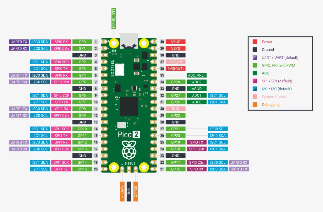
The below figure from the Raspberry Pi documentation shows the pinout and design of the Raspberry Pi Pico. Let's start by understanding the key features of the RP2040 microcontroller by Raspberry Pi.
- Dual ARM Cortex-M0+ @ 133MHz
- 264kB on-chip SRAM in six independent banks
- Support for up to 16MB of off-chip Flash memory via dedicated QSPI bus.
- DMA controller
- Fully-connected AHB crossbar
- Interpolator and integer divider peripherals
- On-chip programmable LDO to generate core voltage
- 2 on-chip PLLs to generate USB and core clocks
- 30 GPIO pins, 4 of which can be used as analogue inputs
- Peripherals
These are the different communication ports used for tasks like sensors, displays, connecting with multiple other devices, controlling the brightness of LEDs or the speed of motors, allowing it to connect to other USB devices, and reading data from sensors.
- 2 UARTs
- 2 SPI controllers
- 2 I2C controllers
- 16 PWM channels
- USB 1.1 controller and PHY, with host and device support
- 8 PIO state machines
This means the Pico has two processors that can operate at a speed of 133 million cycles per second. The higher the speed, the faster its performance and efficiency.
It has 264 KB of short-term memory on the device, which is divided into six parts. This helps it store and access data quickly while it is working.
This is long-term memory, which has 16 MB of storage and uses the QSPI protocol. Quad Serial Peripheral Interface (QSPI) is a serial communication interface designed for talking to flash chips. This is where you store your programs and data.
A Direct Memory Access (DMA) controller is a hardware device that transfers data between memory and other devices without the external processor's support.
Advanced High-performance Bus (AHB) helps data travel in multiple directions without getting stuck. This feature allows different parts of the device to communicate with each other smoothly.
This helps the device handle complex problems.
This is a built-in power regulator in the device that ensures the device gets the right amount of power.
They keep time and keep everything running in sync.
30 general-purpose input/output (GPIO) pins are uncommitted pins in the microcontroller. All of them can be used as digital signal pins, and 4 of them can be used as analogue inputs.
2. Write a program for a microcontroller to interact with
A. Traffic signal simulation
The example traffic signal simulation in WOKWI is incorrect. In the simulation, the lights cycle through red, yellow, and green in a loop, which does not reflect real-world traffic signal behavior.
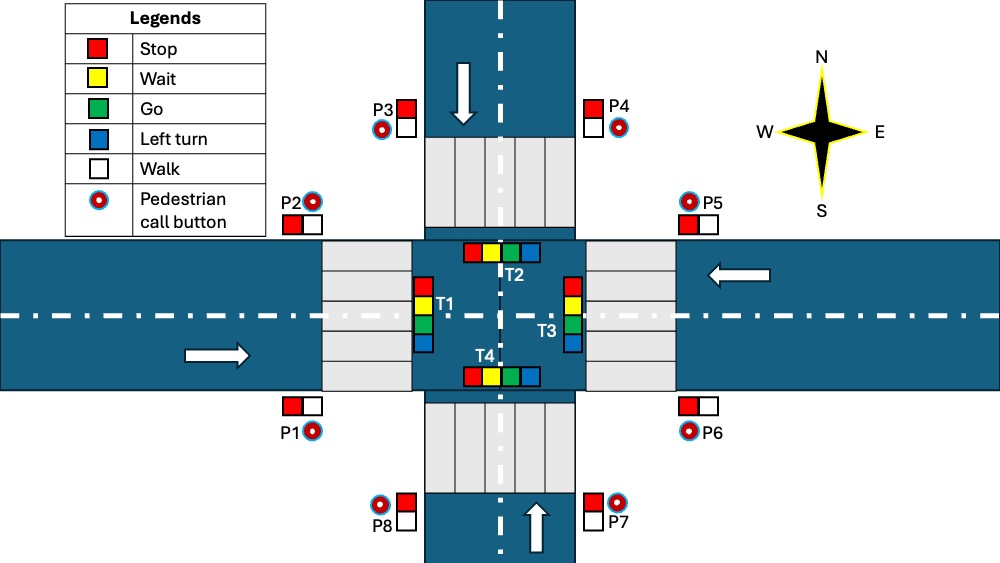
I wanted to simulate a real-world traffic signal system at a two-road intersection, including pedestrian lights. The concept is straightforward. The following figure shows the conceptual diagram of the traffic signal system with pedestrian lights.
Let's start by breaking down the problem.
- If a pedestrian presses the call button at any of the locations (P1, P2, P3, P4, P5, or P6), it should activate all the pedestrian signals in all directions.
- The traffic lights at directions T1 and T3 should always display the same signal at any given time.
- Similarly, the traffic lights at directions T2 and T4 should always display the same signal at any given time.
After this, the complexity of the traffic light system is significantly reduced.
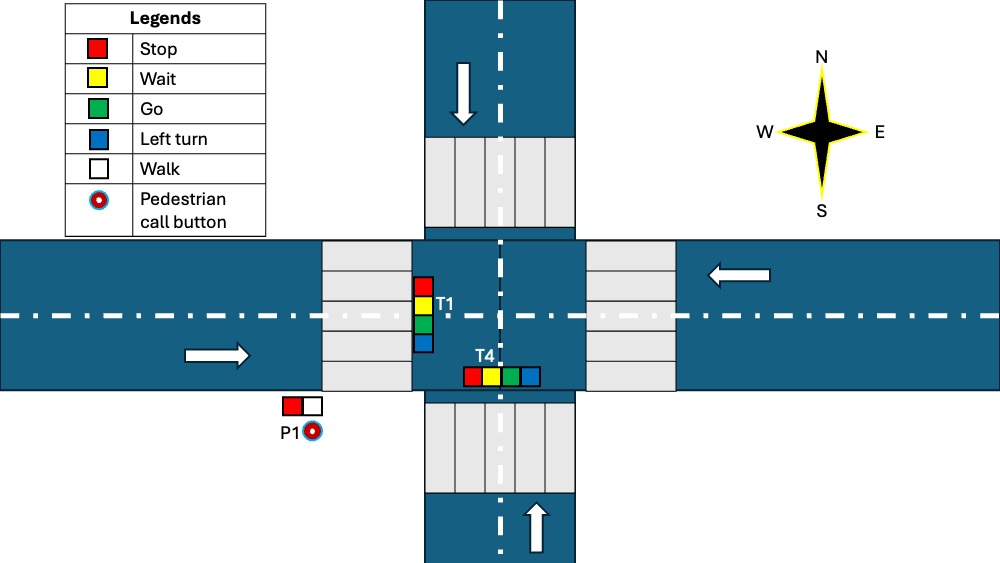
Now we have to control one pedestrian call switch, two pedestrian light signals, and eight traffic light signals. Let's start by defining how long each light should be turned on.
| Light Color | Time (seconds) |
|---|---|
| Green | 20 |
| Blue (Left turn) | 10 |
| Yellow | 3 |
| Pedestrian Walk | 10 |
The values provided above are not precise. They are hypothetical figures used solely for simulating the traffic light on a circuit board for the purposes of this assignment. Now, let's list the necessary components.
| Components | Function |
|---|---|
| RP2040 | To control the entire operation and store the code |
| Resistor | To prevent excessive current flow through the circuit and protect the LED from burning out |
| Relay | Electronic switch to operate the pedestrian signal |
After connecting everything, the electronic circuit board looks like this:
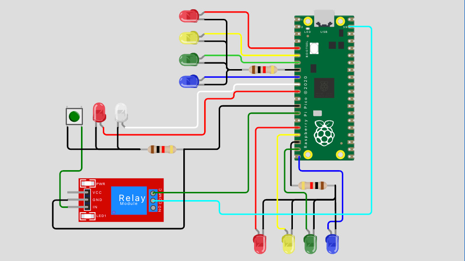
For this simulation, I have chosen the C programming language to write the code in Wokwi.
Finally, the simulation looks like this:
Yuval suggested an alternative method for switch control. It involves using a delay function with a short duration, repeatedly called by the main function to check if the push button is clicked. This approach solved my issue with turning off the switch and also reduced the number of components in the assembly. He also suggested exploring the interrupt function, which I plan to do later.
The current simulation has improved compared to the previous version. The video below is speed up by a factor of 5. (Update: This connection isn’t working. After spending several hours troubleshooting on the breadboard, I identified the issue. Check the next assembly for the correct working simulation. I am keeping this just for the documentation purposes.)
Tuesday: I went to the EECS lab early in the morning to show my simulation to Anthony. He suggested using one resistor for each LED. Although my current design wouldn't have any issues since only one LED turns on per signal group, I decided to follow his advice to be safe. I updated the layout accordingly.
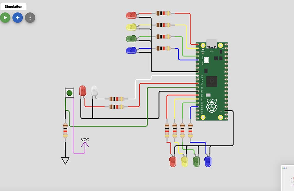
After this the simulation works fine.
                            //Traffic light 1
                            #define RED_T1 0
                            #define YELLOW_T1 1
                            #define GREEN_T1 2
                            #define BLUE_T1 3

                            //Traffic light 4
                            #define RED_T4 10
                            #define YELLOW_T4 11
                            #define GREEN_T4 12
                            #define BLUE_T4 13

                            //Pedestrian P1
                            #define RED_P1 8
                            #define WHITE_P1 7
                            #define switch_1 9

                            //defining variables
                            int num;
                            int i;
                            int val = 0;
                            int oldValue = LOW;


                            void setup() {
                              // Traffic light 1
                              pinMode(RED_T1, OUTPUT);
                              pinMode(YELLOW_T1, OUTPUT);
                              pinMode(GREEN_T1, OUTPUT);
                              pinMode(BLUE_T1, OUTPUT);

                              // Traffic light 4
                              pinMode(RED_T4, OUTPUT);
                              pinMode(YELLOW_T4, OUTPUT);
                              pinMode(GREEN_T4, OUTPUT);
                              pinMode(BLUE_T4, OUTPUT);

                              // Pedestrian P1
                              pinMode(RED_P1, OUTPUT);
                              pinMode(WHITE_P1, OUTPUT);
                              pinMode(switch_1, INPUT);
                            }

                            void delay_1(int num) {
                              for (int i = 0; i < num; i++) {
                                int newValue = digitalRead(switch_1);
                                if(newValue != oldValue) {
                                  val = 1;
                                }
                                printf("%d",val);
                                delay(10);
                              }
                            }
                            void traffic_cycle(){
                              digitalWrite(RED_T1, LOW);
                              digitalWrite(GREEN_T1, HIGH);
                              delay_1(500);

                              digitalWrite(GREEN_T1, LOW);
                              digitalWrite(BLUE_T1, HIGH);
                              delay_1(300);

                              digitalWrite(BLUE_T1, LOW);
                              digitalWrite(YELLOW_T1, HIGH);
                              delay_1(100);

                              digitalWrite(YELLOW_T1, LOW);
                              digitalWrite(RED_T1, HIGH);
                              delay_1(50);

                              digitalWrite(RED_T4, LOW);
                              digitalWrite(GREEN_T4, HIGH);
                              delay_1(500);

                              digitalWrite(GREEN_T4, LOW);
                              digitalWrite(BLUE_T4, HIGH);
                              delay_1(300);

                              digitalWrite(BLUE_T4, LOW);
                              digitalWrite(YELLOW_T4, HIGH);
                              delay_1(100);

                              digitalWrite(YELLOW_T4, LOW);
                              digitalWrite(RED_T4, HIGH);
                              delay_1(50);
                            }

                            void pedestrian(){
                              digitalWrite(RED_P1, LOW);
                              digitalWrite(WHITE_P1, HIGH);
                              delay_1(200);

                              digitalWrite(WHITE_P1, LOW);
                              digitalWrite(RED_P1, HIGH);
                              delay_1(50);
                              val = 0;
                            }

                            int main(){
                              Serial.begin(115200);
                              setup();
                              digitalWrite(RED_T1, HIGH);
                              digitalWrite(RED_T4, HIGH);
                              digitalWrite(RED_P1, HIGH);

                              while(true){
                                traffic_cycle();
                                //check if pedestrian button is pressed or not?
                                if(val == 1){
                                  pedestrian();
                                }
                              }
                            return 0;
                            }
B. Adding the Counter for the Pedestrian Walk
The pedestrian walk signal is active for 10 seconds. The countdown timer indicates whether it's safe to start crossing the street. I also added a counter to the pedestrian light, which helps pedestrians know how much time is left before the light turns off.
                            #include

                                //Traffic light 1
                                #define RED_T1 0
                                #define YELLOW_T1 1
                                #define GREEN_T1 2
                                #define BLUE_T1 3

                                //Traffic light 4
                                #define RED_T4 10
                                #define YELLOW_T4 11
                                #define GREEN_T4 12
                                #define BLUE_T4 13

                                //Pedestrian P1
                                #define RED_P1 8
                                #define WHITE_P1 7
                                #define switch_1 9
                                int oldValue = LOW;

                                //definition for counter
                                const int CLK = 26;
                                const int DIO = 27;

                                //defining variables
                                int num;
                                int i;
                                int val = 0;
                                int ped = 0;

                                TM1637 tm(CLK, DIO);
                                unsigned int counter = 0;

                                void setup() {
                                  // Traffic light 1
                                  pinMode(RED_T1, OUTPUT);
                                  pinMode(YELLOW_T1, OUTPUT);
                                  pinMode(GREEN_T1, OUTPUT);
                                  pinMode(BLUE_T1, OUTPUT);

                                  // Traffic light 4
                                  pinMode(RED_T4, OUTPUT);
                                  pinMode(YELLOW_T4, OUTPUT);
                                  pinMode(GREEN_T4, OUTPUT);
                                  pinMode(BLUE_T4, OUTPUT);

                                  // Pedestrian P1
                                  pinMode(RED_P1, OUTPUT);
                                  pinMode(WHITE_P1, OUTPUT);
                                  pinMode(switch_1, INPUT);

                                  //setup for the counter
                                  tm.init();
                                  tm.set(BRIGHT_TYPICAL);
                                }

                                void delay_1(int num) {
                                  for (int i = 0; i < num; i++) {
                                    int newValue = digitalRead(switch_1);
                                    if(newValue != oldValue) {
                                      val = 1;
                                    }
                                    counter = i/100;
                                    if (ped == 1){
                                      tm.display(0, (counter / 1000) % 10);
                                      tm.display(1, (counter / 100) % 10);
                                      tm.display(2, (counter / 10) % 10);
                                      tm.display(3, counter % 10);
                                    }
                                    else {
                                      tm.display(0, 0);
                                      tm.display(1, 0);
                                      tm.display(2, 0);
                                      tm.display(3, 0);
                                    }
                                    delay(10);
                                  }
                                }

                                void traffic_cycle(){
                                  delay_1(1);
                                  digitalWrite(RED_T1, LOW);
                                  digitalWrite(GREEN_T1, HIGH);
                                  delay_1(2000);

                                  digitalWrite(GREEN_T1, LOW);
                                  digitalWrite(BLUE_T1, HIGH);
                                  delay_1(1000);

                                  digitalWrite(BLUE_T1, LOW);
                                  digitalWrite(YELLOW_T1, HIGH);
                                  delay_1(300);

                                  digitalWrite(YELLOW_T1, LOW);
                                  digitalWrite(RED_T1, HIGH);
                                  delay_1(100);

                                  digitalWrite(RED_T4, LOW);
                                  digitalWrite(GREEN_T4, HIGH);
                                  delay_1(2000);

                                  digitalWrite(GREEN_T4, LOW);
                                  digitalWrite(BLUE_T4, HIGH);
                                  delay_1(1000);

                                  digitalWrite(BLUE_T4, LOW);
                                  digitalWrite(YELLOW_T4, HIGH);
                                  delay_1(300);

                                  digitalWrite(YELLOW_T4, LOW);
                                  digitalWrite(RED_T4, HIGH);
                                  delay_1(100);
                                }

                                void pedestrian(){
                                  digitalWrite(RED_P1, LOW);
                                  digitalWrite(WHITE_P1, HIGH);
                                  ped = 1;
                                  delay_1(1000);
                                  ped = 0;

                                  digitalWrite(WHITE_P1, LOW);
                                  digitalWrite(RED_P1, HIGH);
                                  delay_1(100);
                                  val = 0;
                                }

                                int main(){
                                  Serial.begin(115200);
                                  setup();
                                  digitalWrite(RED_T1, HIGH);
                                  digitalWrite(RED_T4, HIGH);
                                  digitalWrite(RED_P1, HIGH);

                                  while(true){
                                    traffic_cycle();
                                    //check if pedestrian button is pressed or not?
                                    if(val == 1){
                                      pedestrian();
                                    }
                                  }
                                return 0;
                                }
C. Other projects
I experimented with various sensors and input/output devices in the Wokwi simulator. The one I enjoyed the most was controlling a servo motor with a motion sensor.
                            //Second project for the HTMAA class.
                            #include

                            Servo servo_left;  // create servo object for left servo
                            Servo servo_right; //create servo object for right servo
                            #define motion_left 16
                            #define motion_right 17

                            int pos = 0;    // variable to store the servo position
                            float val_left;
                            float val_right;

                            void setup() {
                            Serial1.begin(115200);
                            //Servo Control
                            servo_left.attach(0);
                            servo_right.attach(1);
                            pinMode(motion_left, INPUT);     // declare sensor as input
                            pinMode(motion_right, INPUT);     // declare sensor as input
                            }

                            void loop() {
                            val_left = digitalRead(motion_left);  // read from left motion sensor
                            val_right = digitalRead(motion_right); //read from right motion sensor
                            if (val_left == HIGH) {            // check if the input from left motion sensor is HIGH
                                for (pos = 0; pos <= 90; pos += 1) {
                                // in steps of 1 degree
                                servo_left.write(pos);
                                servo_right.write(pos);
                                delay(50); // waits 15ms for the servo to reach the position
                                }
                                val_left = 0;
                            }
                            if (val_right == HIGH) {            // check if the input from left motion sensor is HIGH
                                for (pos = 0; pos <= 90; pos += 1) {
                                // in steps of 1 degree
                                servo_left.write(180-pos);
                                servo_right.write(180-pos);
                                delay(50); // waits 15ms for the servo to reach the position
                                }
                                val_right = 0;
                            }
                            }
3. Test it on a development board and/or try different languages and/or development environments
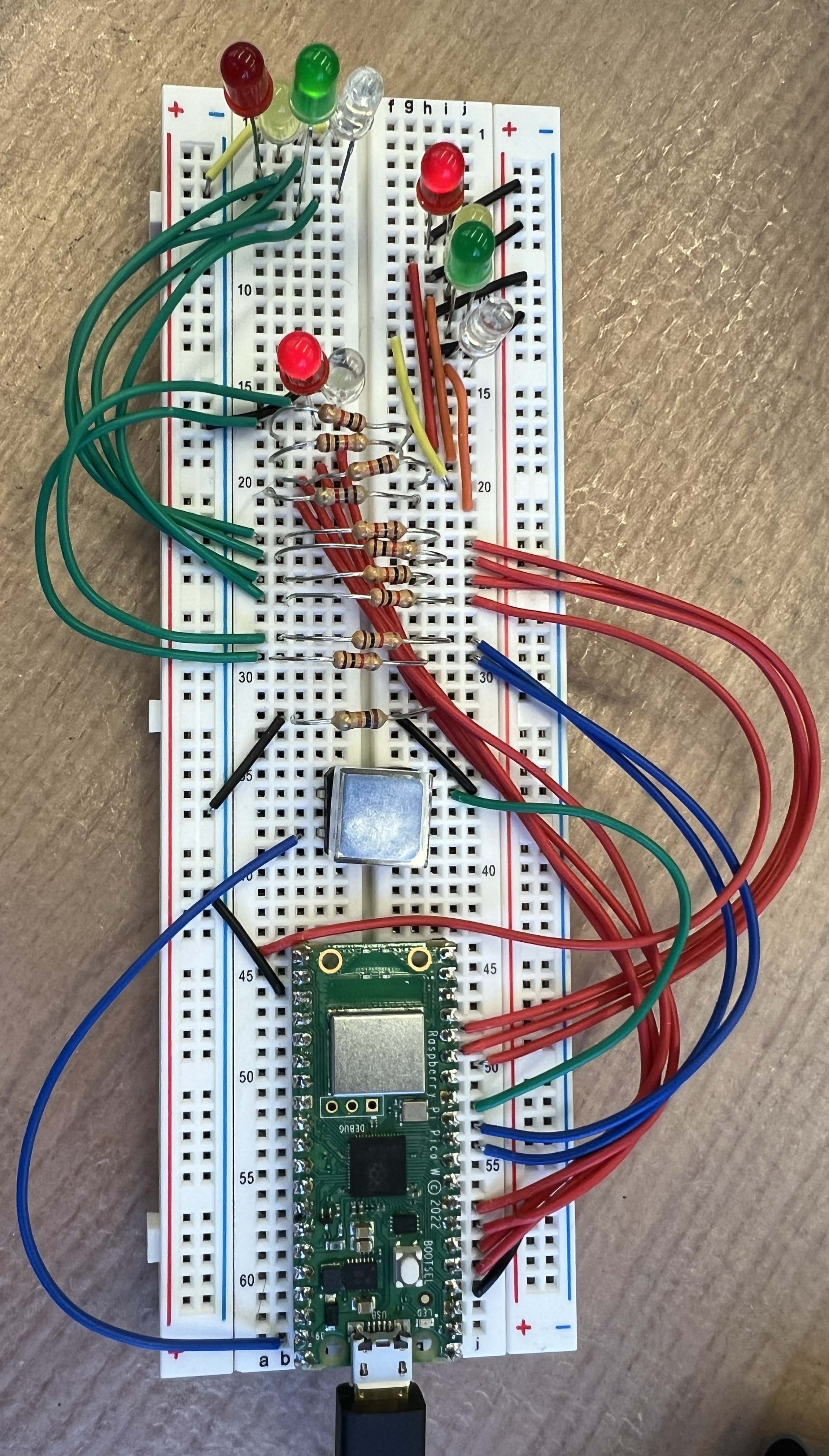
I tried assembling the traffic light signal in the breadboard and bingo I did it with the help from Sam and Anthony.
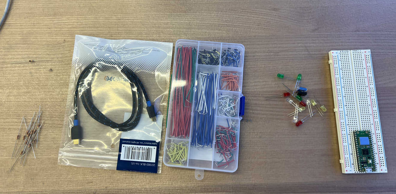
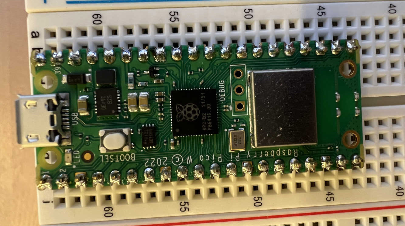
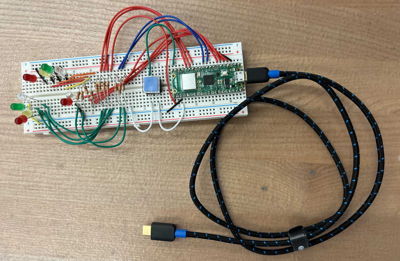
After several hours of learning and trying to connect components on the breadboard, it finally worked. I had to change some of the pins connected to certain ports because the original ones weren’t functioning, though I’m not sure why. Another lesson I learned after assembling the electronics is that what works in simulation might not always work on the actual board. For instance, my switch connection worked perfectly in the simulation but failed on the real board, requiring reconfiguration. This highlights the importance of good circuit design, as mentioned earlier.
Here is the picture of the working circuit board.
Due to limited time and wrestling with the breadboard over a silly mistake I made, I wasn’t able to try MicroPython as I had hoped. I’ll definitely explore it in a future project. That’s all for this week—I’m really excited for 3D printing week coming up!