Summary
Wow, what a journey this project has been! What started as a fun idea—a smart pet rock—turned into a wild ride of learning and experimenting. I had no idea how much I’d end up diving into engineering design, electronics, programming, and even figuring out how to work with something as unpredictable as a real rock. Along the way, I got to mess around with tools like Fusion 360 for 3D design, create custom circuit boards, and write a bunch of Arduino code. There were definitely some head-scratching moments, like cramming sensors and motors into tight spaces while making sure everything actually worked. But seeing this crazy idea come to life taught me so much more than I ever expected.
Honestly, the technical stuff was just one part of it. This project also made me realize how important it is to keep trying and tweaking things when they don’t work (and trust me, plenty didn’t!). From sketching ideas and dealing with failed 3D prints to fixing stubborn code and finally piecing it all together, every step taught me something new. I also couldn’t have done this without the help of my peers, mentors, and the lab resources—collaborating with them gave me a ton of fresh ideas and tips. In the end, this smart pet rock isn’t just a project; it’s a mix of everything I’ve learned and loved about engineering, creativity, and, well, rocks! I’m so glad I got to bring all of that together into something I’m really proud of.
Acknowledgment
I would like to express my heartfelt gratitude to everyone who helped me directly or indirectly throughout this course. First and foremost, I want to thank Prof. Neil Gershenfeld for offering such a wonderful subject and envisioning this course. I am deeply grateful to my supervisor, Prof. Herbert Einstein, for encouraging me to take this course and for his continuous support and encouragement throughout the semester. I would also like to thank Omar Al-Dajani and Rafael Villamor Lora for their encouragement and motivation to take this class.
A special thank you goes to Anthony Pennes. Words cannot adequately express my gratitude for his guidance and support. I truly believe there are no words in the English dictionary sufficient to thank him. I would not have been able to navigate this course without his help. His smile and encouragement always motivated me to work harder. Thank you, Anthony, for everything!
I would also like to thank the other amazing TAs and staff members, including Sam, Yuval, Alec, Dave, and everyone else who contributed directly or indirectly to my success in this class. Lastly, I am grateful to my talented classmates, both from EDS and beyond, for making this class so enjoyable and cheerful. Thank you very much, everyone!
TL;DR
This documentation is quite long. If you don't want to dive into all the details, I’ve summarized answers to the key questions Neil listed in the final project week’s page. Let’s get started!
1. What does it do?
Ever wondered what it would be like to have a smart pet rock that interacts with you and reminds you of important meetings or appointments so you never miss them? Well, here it is! This is a pet rock with one eye (like Stuart from Minions). It can track your movement, keep looking at you, and has a reminder feature with beautiful sound alerts and a colorful LCD display.
2. Who’s done what beforehand?
Actually, nobody has created a smart pet rock before. I found one example on the Fab Academy, but it wasn’t smart. However, many people have explored motion detection, eye mechanisms, LCD displays, sound systems, and reminder features. I reviewed several final projects to optimize my work and learn from others’ mistakes.
3. What sources did you use?
I used a variety of resources to design this project. For the eye mechanism, I was inspired by two YouTube videos: Video 1 and Video 2. The stepper motor and gear system came from our own design during Machine Week. The sensor code was adapted from Neil’s examples on the class website and additional libraries from Adafruit. A special thanks to Anthony, who’s a master of everything, and the other TAs whose advice greatly improved this project.
4. What did you design?
Almost everything! The most organic design I created was the eye mechanism. A major challenge was fitting the eye into a 2” diameter hole. I found similar designs online, but they required a lot of space behind the eye for movement. The space constraint was tricky, but I improved the design so it fits perfectly into the circular 2” hole. The 2” size limitation was due to the servo motors available, not the design itself. In the future, smaller servos could allow for a more compact version. Apart from this, most of my designs were influenced by existing solutions, but I improved them to suit my needs.
5. What materials and components were used?
- Rock
- 2 x Micro Servo 9g S51 Motors
- 2 x Raspberry Pi Pico W
- VL53L7CX Time of Flight Sensor
- 2.4" TFT LCD Touch Screen Module
- Aluminum extrusion frame
- 3D-printed mounts for components and eye glass
- SPEAKER 8OHM 500MW TOP PORT 92DB
- MAX98357A breakout board
- Hall effect sensors
- Black acrylic board (for box and gears)
- Fabric (for eye glass strap)
- Nema 17 Stepper Motor
- Square Turntables (Lazy Susan)
- DRV8428PPWPR stepper motor driver
- Miscellaneous electronics: resistors, capacitors, voltage regulators, connectors, etc.
- Miscellaneous hardware: screws, T-nuts, nuts, bolts, etc.
6. Where did they come from?
The rock was a gift from Steve. I shared my project idea, and he found the rock on a beach near Boston. Most of the other components were sourced by Anthony, who got them from Amazon, Pololu, Digi-Key, and McMaster. I also designed many components in CAD and 3D printed them using a Prusa printer at EDS.
7. How much did they cost?
I kept track of all the items, their sources, and costs in an Excel sheet (I did not payed but would cost if I had to buy). You can download it here:
8. What parts and systems were made?
Most of the mounts were designed and 3D printed in-house. The eye mechanism system was designed, printed, and assembled. The box housing the electronics was modeled in CAD, cut, and fabricated in EDS. The rock was drilled at the Peč Lab Experimental Rock Deformation lab with help from Uli. Circuit boards were milled and soldered at EDS.
9. What tools and processes were used?
- Fusion 360 (3D design)
- 3D printing (Prusa printer)
- Arduino IDE (programming the Raspberry Pi Pico W)
- Soldering tools
- Basic hand tools (screwdrivers, pliers)
- Rock core drill
- Bantam end mills (PCB milling)
- Band saw (cutting aluminum extrusion)
- Laser cutter
- Brother SE1800 sewing machine
10. What questions were answered?
Questions about eye mechanism control, power management, sensor integration, stepper motor control, and rock drilling were addressed. I optimized motor rotation angles for smoother movement and improved system performance.
11. What worked? What didn’t?
Almost everything I aimed for worked as of writing this (just before the final presentation). The only incomplete feature is integrating a calendar API through Wi-Fi so the rock can remind me of tasks. The motion detection system also needs improvement since the time-of-flight sensor’s 8x8 resolution is too coarse for precise tracking. Despite this, with help from the TAs and online resources, I got most features working.
12. How was it evaluated?
I evaluated each component based on whether it met my expectations. The motion detection system lags and doesn’t always move in the correct direction. On the other hand, the LCD screen and sound system exceeded my expectations and performed extremely well.
13. What are the implications?
It highlights the potential of using natural materials like rocks in digital fabrication, which could inspire future projects.
Motivation
I'm a geotechnical engineer/rock mechanist working in an experimental rock mechanics lab, where my job—essentially—is to break rocks. Specifically, I study electrical fracturing, using electric currents to fracture rock. But while brainstorming my final project, I had this wild thought: what if rocks had souls? And here we are, shattering them without a second thought—haha, it’s kind of dark but funny, right?
It got me thinking about how much we, as humans, owe to rocks. From the early days when we sparked fire by rubbing stones together, to the intricate rock carvings of ancient civilizations, and now even using minerals for our modern tech, rocks have given us so much. So, in a way, I wanted to show some appreciation for all they've done for us. That’s when I thought, why not create a smart pet rock? A little companion for rock mechanics—something cute and fun, but also a nod to all the ways rocks have helped shape our world.
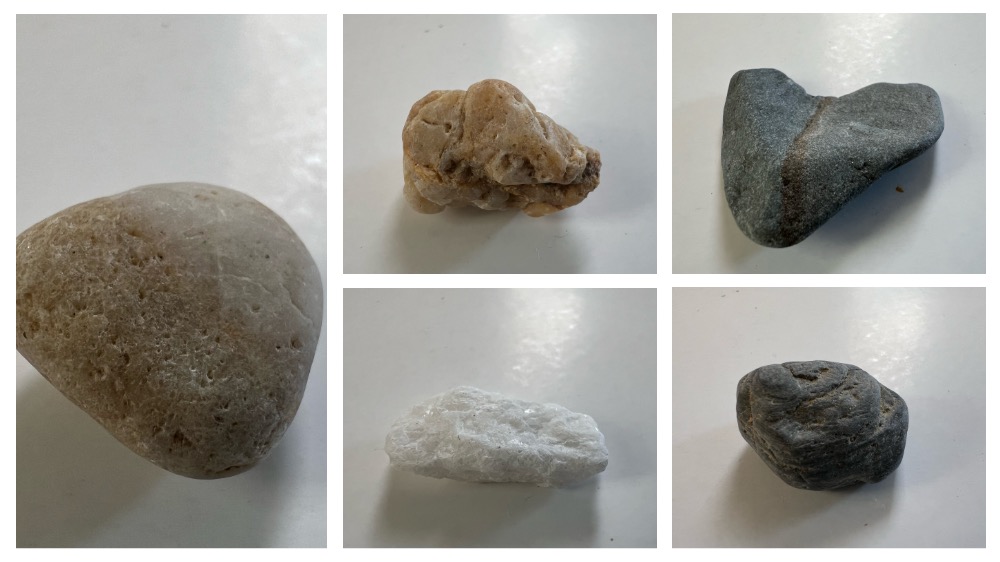
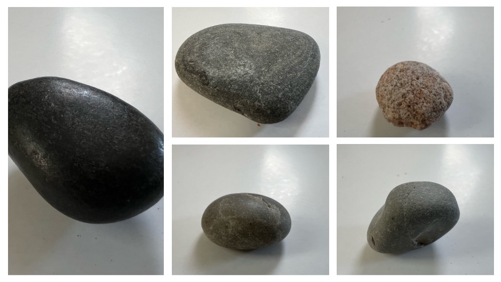
Concept
My plan is to carve out a large riverbed boulder or a nearly round rock. This rock will sit on a 3D-printed box that will also contain other essential electronics and minicomputers. The main features of this pet rock will include eyes that light up when someone approaches or when it hears someone talking. Additionally, it can track people’s movements, so the eyes will follow anyone moving in front of it. If time and resources permit, I’d like to add speaking capabilities as well. I envision this project as a blend of art, technology, and engineering geology.
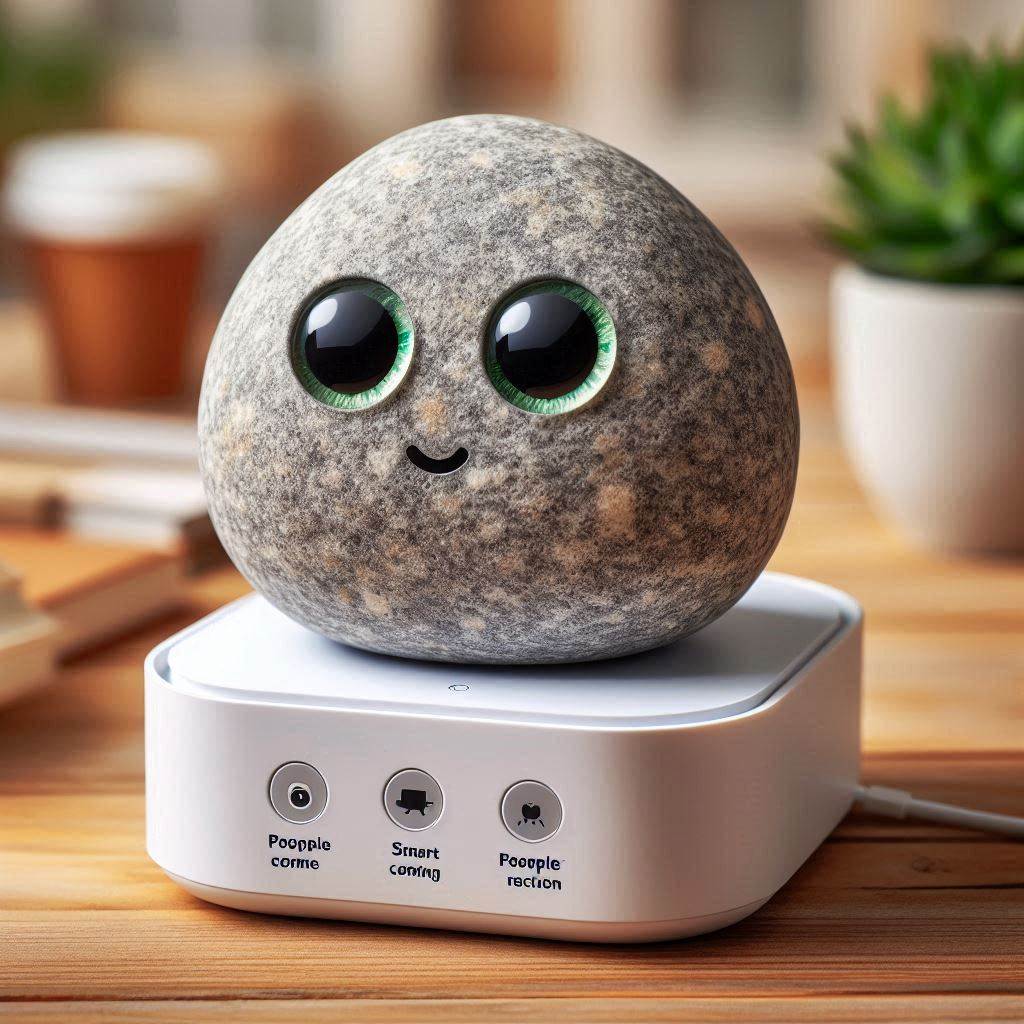
Image generated using DALL-E 3 and the prompt: "A smart rock pet with two eyes and a smart sensor that can see people coming and speaking, reacting according to people's reactions. The rock is placed on a platform like a box where all the electronics are stored."
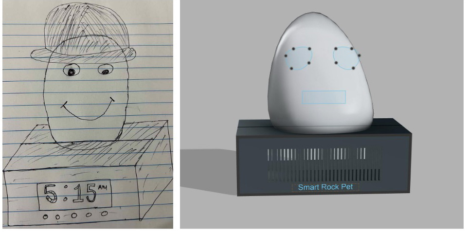
Concept Drawing in Fusion360
This Fusion design will be updated in the coming weeks.
Progress Documentation as it goes
Sept 30: Got the Rock
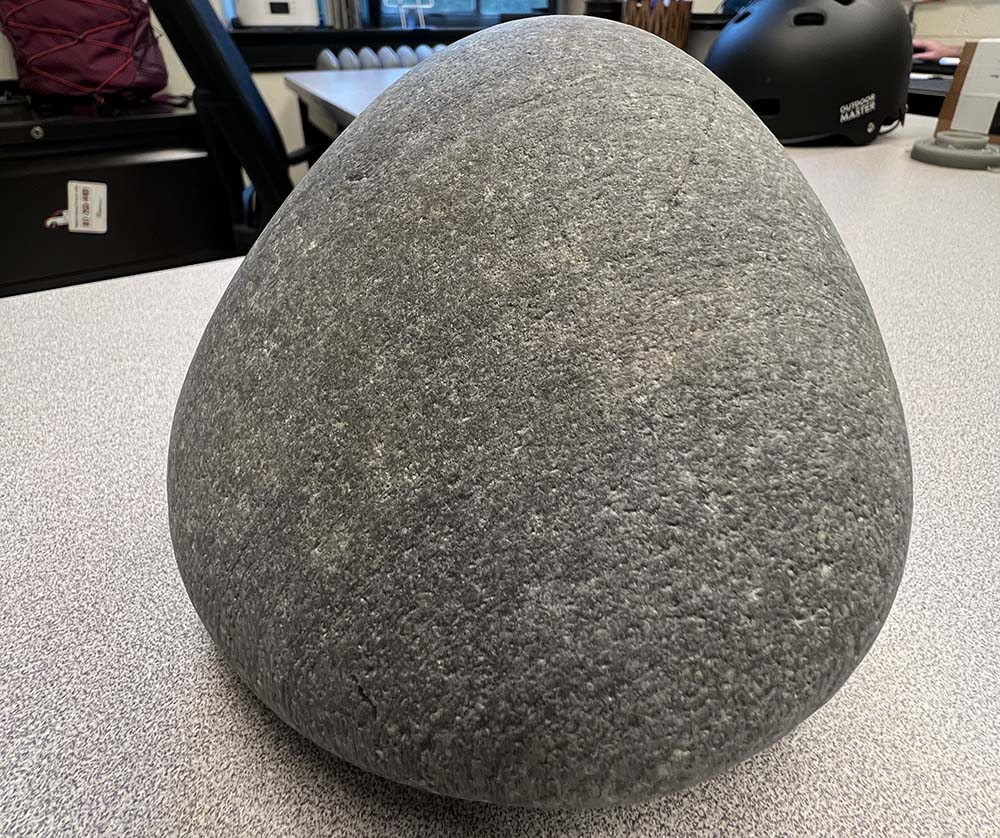
I began brainstorming how to start the project and discussed my idea with several people. The main challenge I identified was carving the rock. My initial thought was to carve it directly, but that seemed quite difficult. Then Steve suggested a better approach—drilling the rock at a specific angle and diameter to create space for the eyes and electronic components.
Oct 8: Electronic Board Design
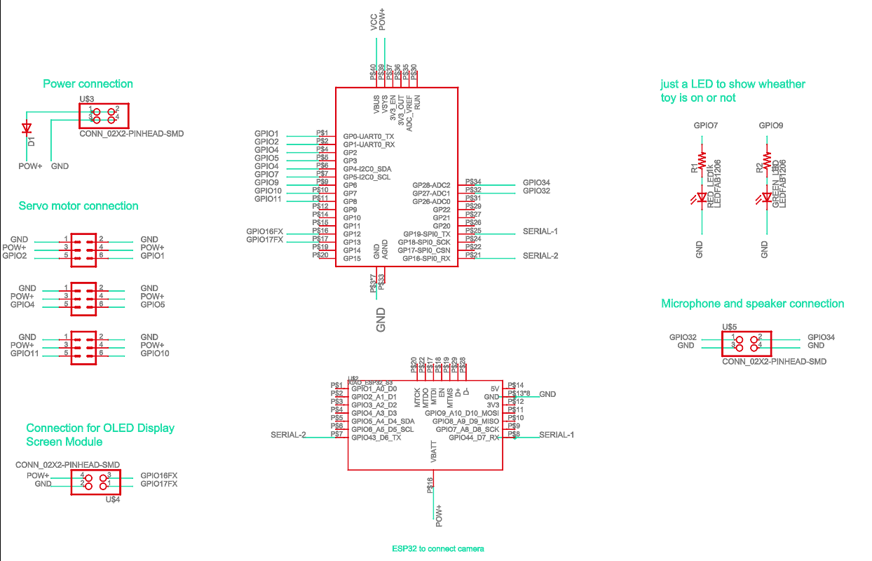
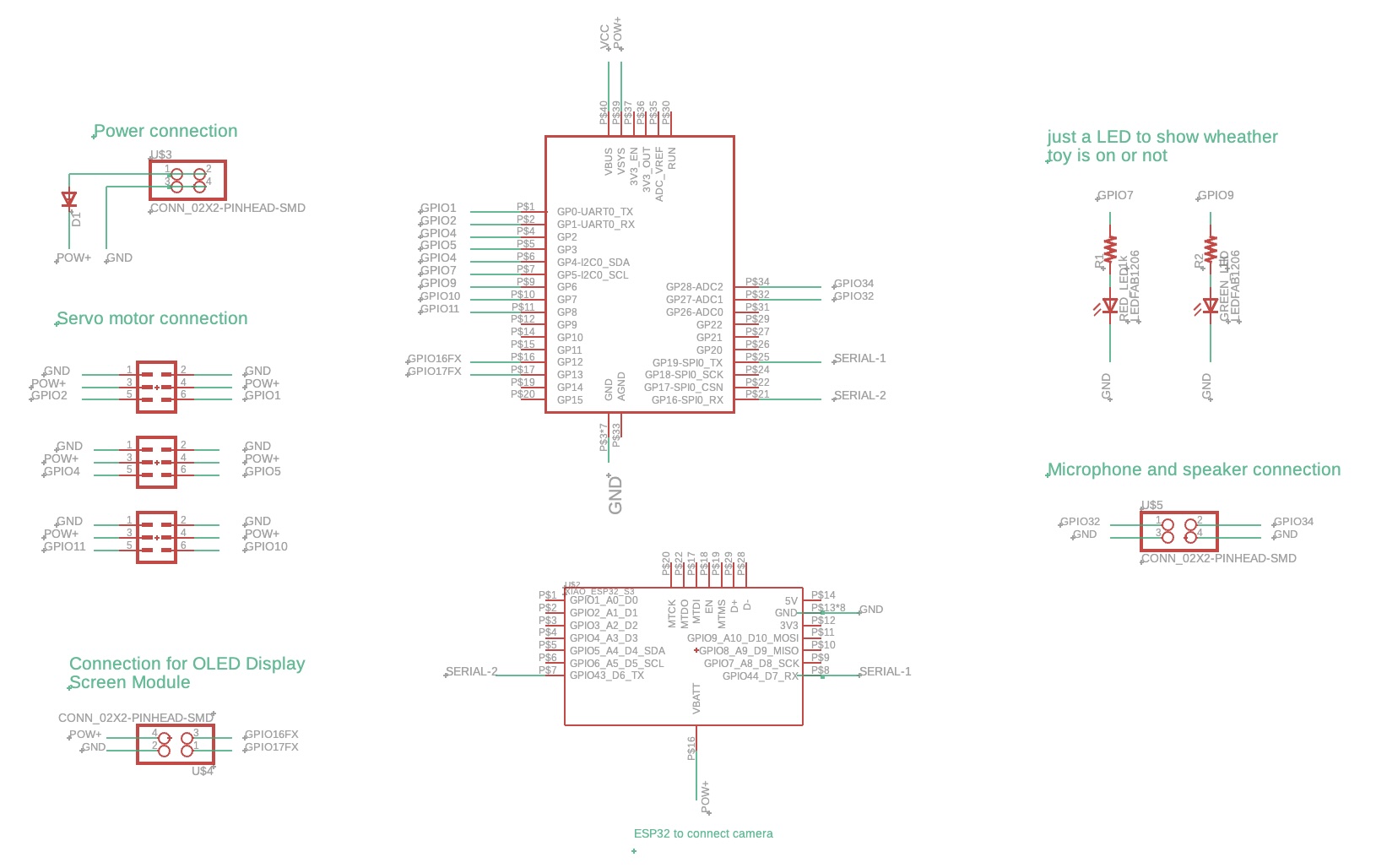
Alright, let's break down what I need for the board for my final project. First, the board should be able to support Wi-Fi communication or direct message connection with a nearby computer that controls most of the tasks. It also needs to control four servo motors for eye movement and one larger servo to rotate the rock (though that part’s optional) for the rock toy. I’d also like an LED screen (now I am considering OLED screen) to display some messages and a few smaller LEDs to indicate power status or other simple info. On top of that, I want to connect a camera module (camera module can be directly connected to ESP32, so I am using that) to the board to track people and adjust the eye movement based on that. And finally, the board should connect to a speaker for audio output. That's what I have in mind so far.
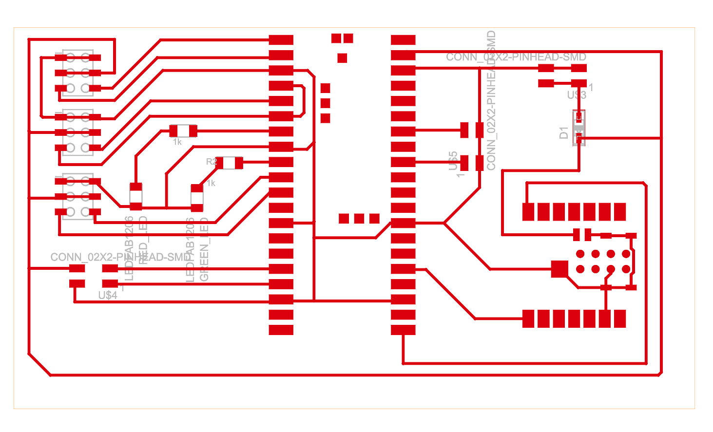
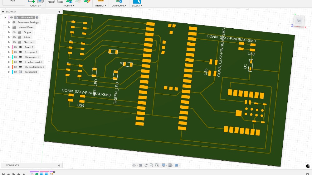
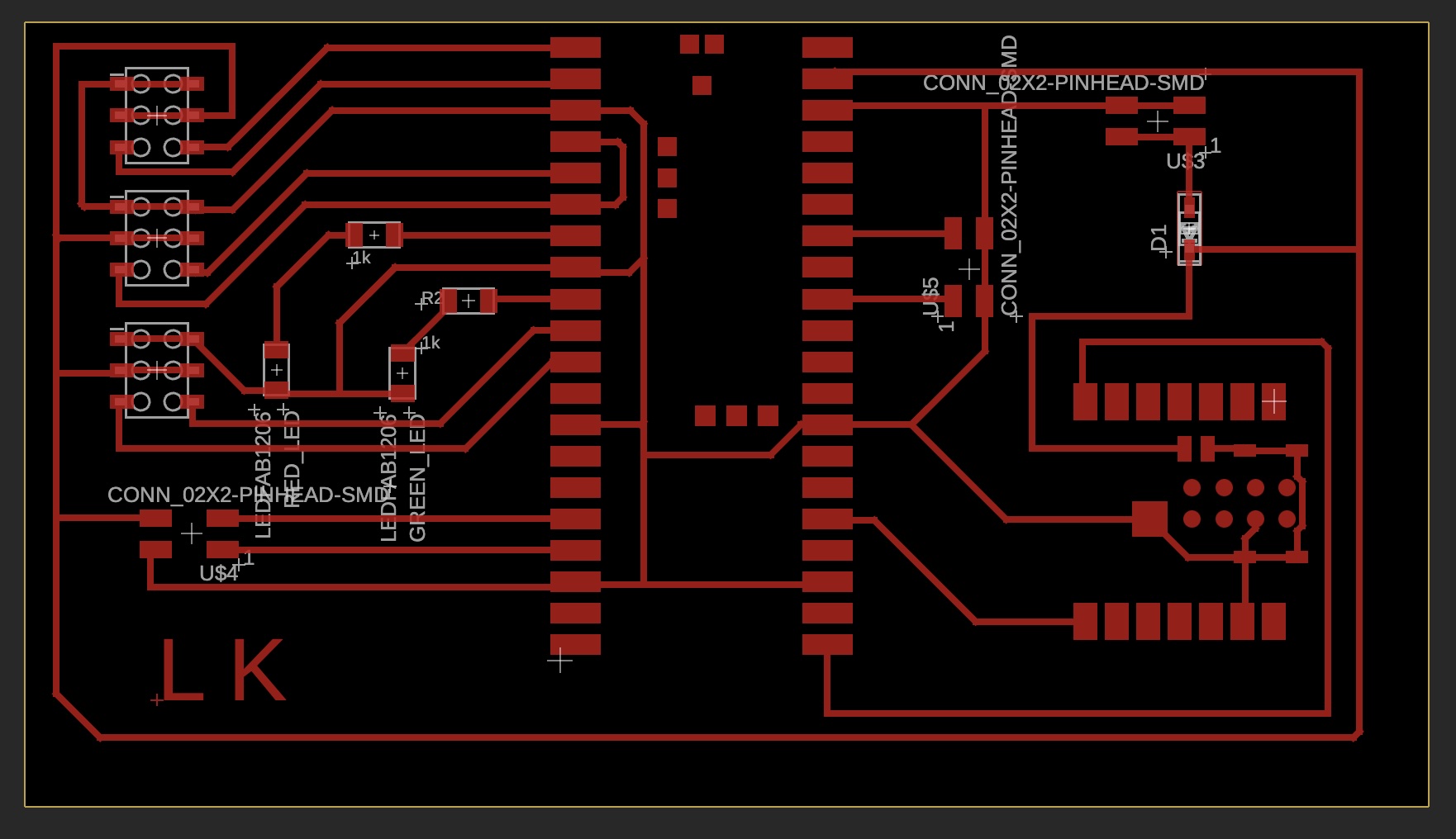
After several trials and errors, and consulting with Anthony and Sam, I finally came up with the version 0 (V0) of the board for my final project. There isn’t too much happening on the board—it's primarily designed to house a Raspberry Pi Pico and an ESP32, both of which have their own microcontrollers.
Since I need to use five servo motors, the power from the Raspberry Pi Pico alone won’t be enough. So, I decided to connect an external power supply. To prevent any potential damage from power connection errors in the future, I'm adding a diode to ensure the current flows in only one direction.
The Raspberry Pi Pico and the ESP32 are connected in series for communication between the two microcontrollers. I’m also adding a four-pin output connector for the OLED display, and another four-pin output for the microphone and speaker. Even though I don’t have immediate plans to use the microphone, it would be great to incorporate it as a sensor to detect people.
Schematic
PCB
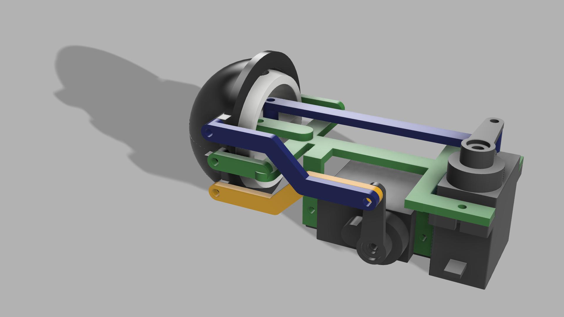
Oct 10: Eye Mechanism (V0)
I spent the whole day 3D designing the eye mechanism for my rock toy. I took a lot of inspiration from these two YouTube videos (Video 1 and Video 2). Although my requirements and theirs are different and my CAD skills are not perfect yet, I spent the whole day working on the CAD design.
Oct 16: 3D-Printed Eye Mechanism
I've 3D-printed the components for the eye mechanism, which I'm calling version 0. After assembling it, I noticed several areas for improvement. First, the main frame that supports the servo motor and the eye mechanism isn't strong enough. I may need to rethink the eyelid mechanism—the concept seems to work, but I’m unsure if the servo motor is powerful enough to drive it. The tight connections are causing issues, so I’ll need to revisit the joints and redesign them. Additionally, I'll redesign the connection point between the main frame and the servo motor to ensure it's sturdy enough to resist any unwanted movement.
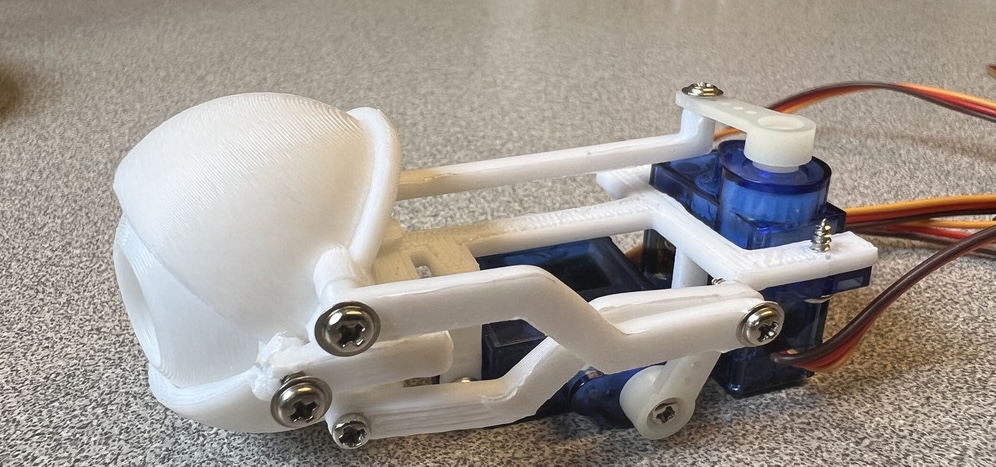
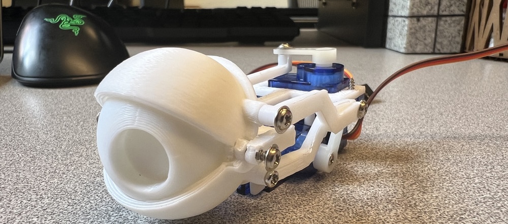
You can see the video here
Board for the Final Project
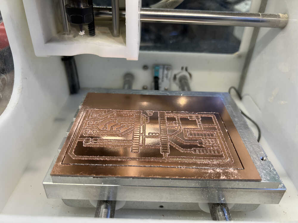
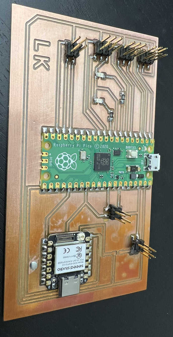
I designed this board on week5. It primarily houses a few LED lights to indicate whether the board is functioning, and it includes two microcontrollers: the Raspberry Pi Pico and the Xiao ESP32. The Raspberry Pi Pico is used to control the servo motors and connects to the microphone and speaker sensors. The ESP32 is mainly responsible for the camera module and its built-in Wi-Fi. The ESP32 will handle the video sensor and communicate with the Raspberry Pi to move the eye mechanism accordingly. This is the plan for now—let’s see how much I can achieve.
1. Fresh after milling:
2. After slight sanding:
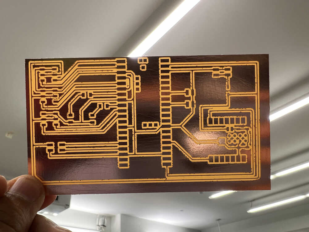
3. Through inspection
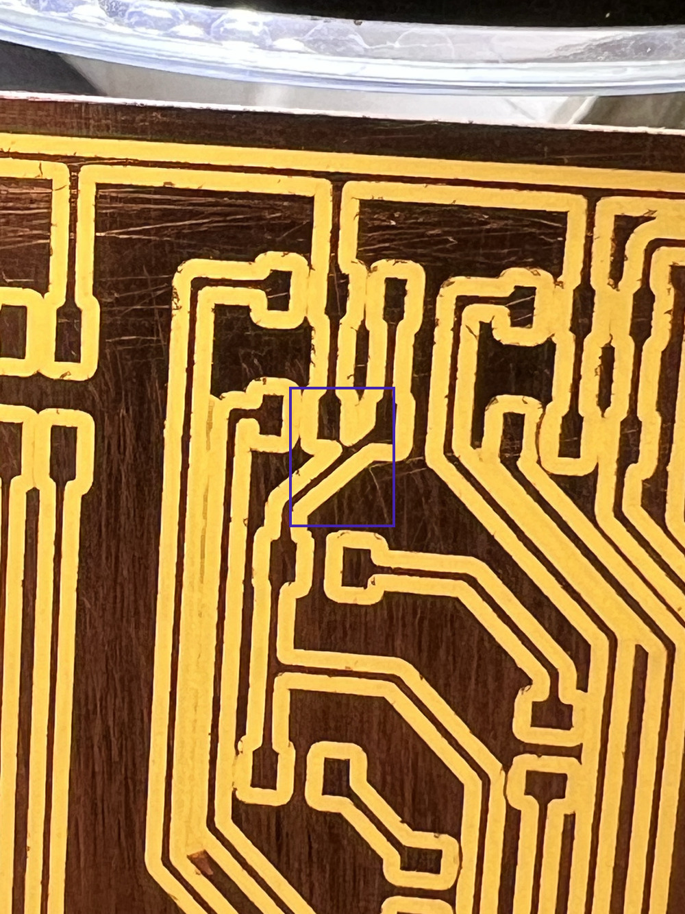
There was an unintended connection between the ground wire and the power due to an imperfect milling process, as shown in the picture below within the blue square. I resolved this by running a sharp object through the milling path.
4. After soldering
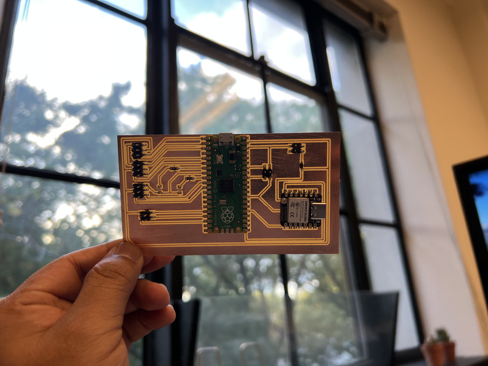
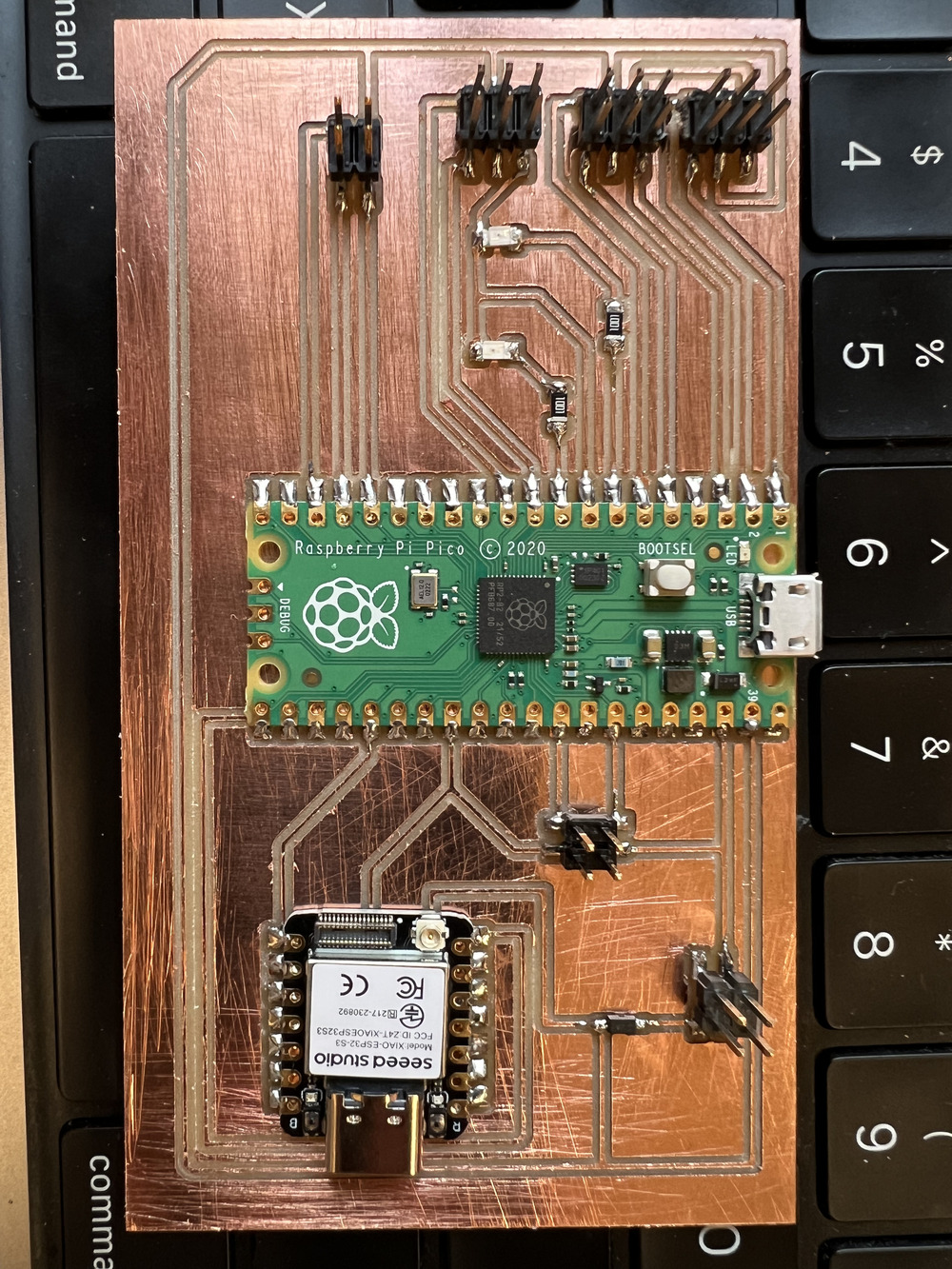
I am still not completely satisfied with my final board design, but I will use it to test the eye mechanism I've prepared for the final project. I'll continue updating the board as I work toward the final version.
Update: October 30
During the week 9: Output Devices, I have changed the board and the work on the eye mechanism. For the full detail how I did that please go the docuementation of week 9. Here I will only put the major milestons.
Board Schematic
PCB Layout
After completing the soldering, this is how the final PCB board looks:
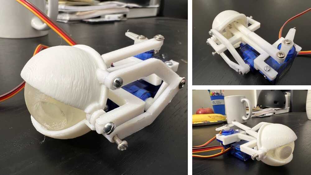
Finally, I connected the eye mechanism to the board. The next step will be to write the code to control it and begin testing.
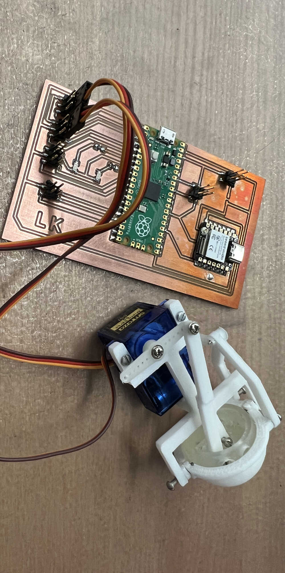
I designed and printed the casing for the eye mechanism and gave the code a little makeover. Now it’s absolutely adorable! Don’t believe me? Take a look for yourself... prepare for cuteness overload!
Update: November 15
We are slowly approaching the final weeks of HTMAA, and there’s still a lot I need to do for my final project. Here, I’m updating the progress I’ve made since my last update.
First and foremost, the biggest bottleneck in my project is drilling the rock to fit the eye mechanism. I consulted with a few people about how to approach this. I also went to the EAPS department to discuss using their rock core driller since I’ve used it before. Unfortunately, I had to leave empty-handed because they don’t have a 2.5" diamond bit for drilling.
I now have three options for drilling the rock. The first option is using the water jet cutter, but it has a disadvantage—it cuts all the way through, which I don’t want. The second option is buying my own 2.5" diamond core bit. The third option is reducing the size of the eye mechanism to fit a 2" diameter hole. For now, I’ve decided to go with the third option and reduce the casing size to 2". I chose this because the 2.5" hole is too large and wouldn’t look good. Reducing the hole size will improve the aesthetics of the project as well.
To implement this, I changed the casing and removed the 3D-printed arm for the eyelid and eyeball mechanism. Instead, I plan to use strong metal wire, which will also make the model more compact. Additionally, I reconfigured the servo motors so they fit inside the 2" diameter cylinder. You can see the updated design of the eye mechanism in the rendering below:
Currently, the parts are being 3D printed, and I plan to test them next week and proceed with drilling the rock. I also 3D-scanned the rock, which you can see in the video below:
Reflection before mid-term review
The mid-term review aims to encourage students to start working on their final projects before it's too late. The instructions for the mid-term review are: "On your final project site, post a system diagram for your project, list the tasks to be completed, create a schedule for completing them, and meet with your local instructor to review these along with your weekly assignments." I believe I have the system diagram for my final project, but I still need to develop a concrete plan for completing the remaining tasks, which I will outline below.
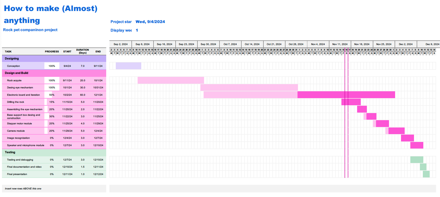 Click here to download the Excel file
Update: November 17
The eye mechanism, modified on November 15, was tested today and works perfectly. Below is a picture of the mechanism and the working video.
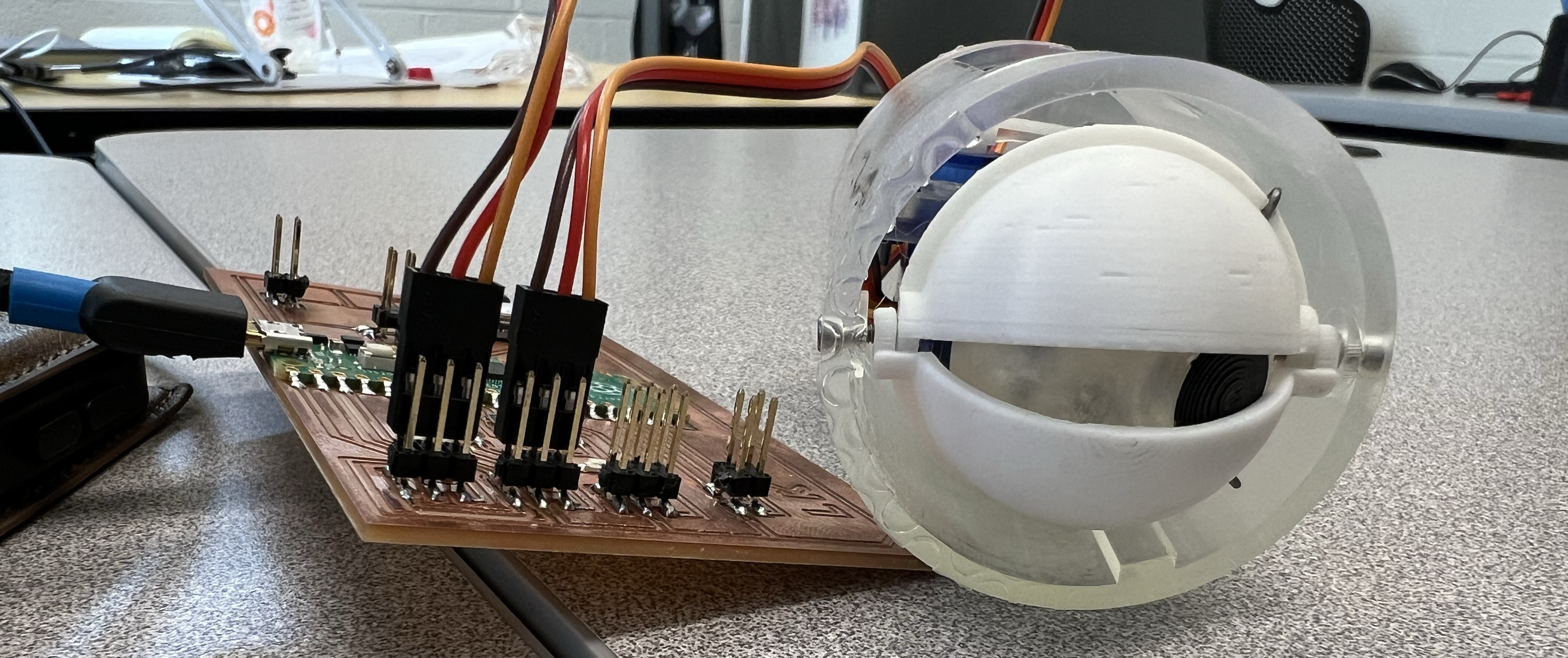
Watch the mechanism in action:
Update: November 24
This is Week 12 of the HTMAA class. I plan to use this week's assignment to progress on my final project while also tackling other essential tasks needed for its completion. Please visit the Week 12 documentation page for a detailed explanation of my work during this week.
Here, I am sharing updates on the design work for the rock's base box, which will house all the electronics and the gear system responsible for turning the rock left and right.
Update: November 27
Today I left my rock in the earth science department for drilling. Special thanks to Uli
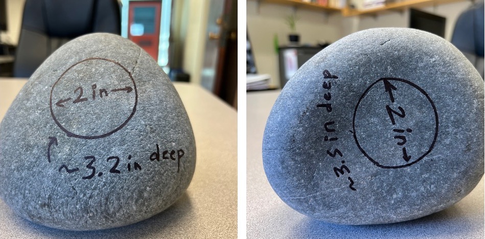
Update: December 1st
One of the biggest milestone achieved this week, I finally drilled my rock using the rock drill core in the Earth and Platenary science department at MIT.
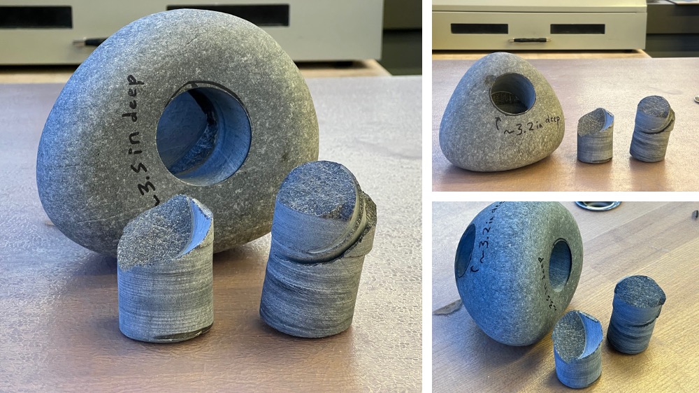
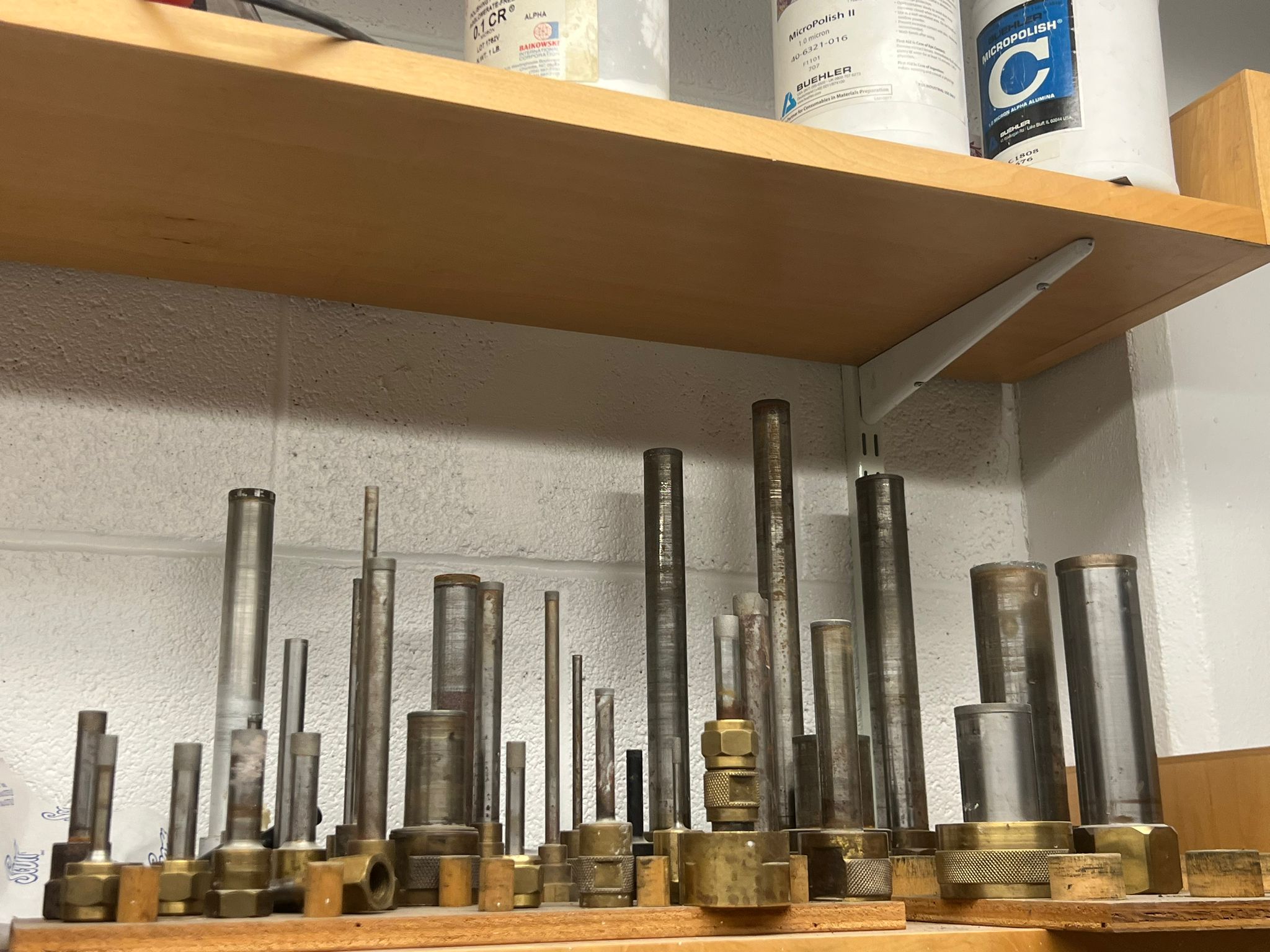
The rock core diamond bit hallow cylindrical bit were used to drill the 2" dia holes. You can see the pictures of the different sizes drill bits in the EAPS at MIT.
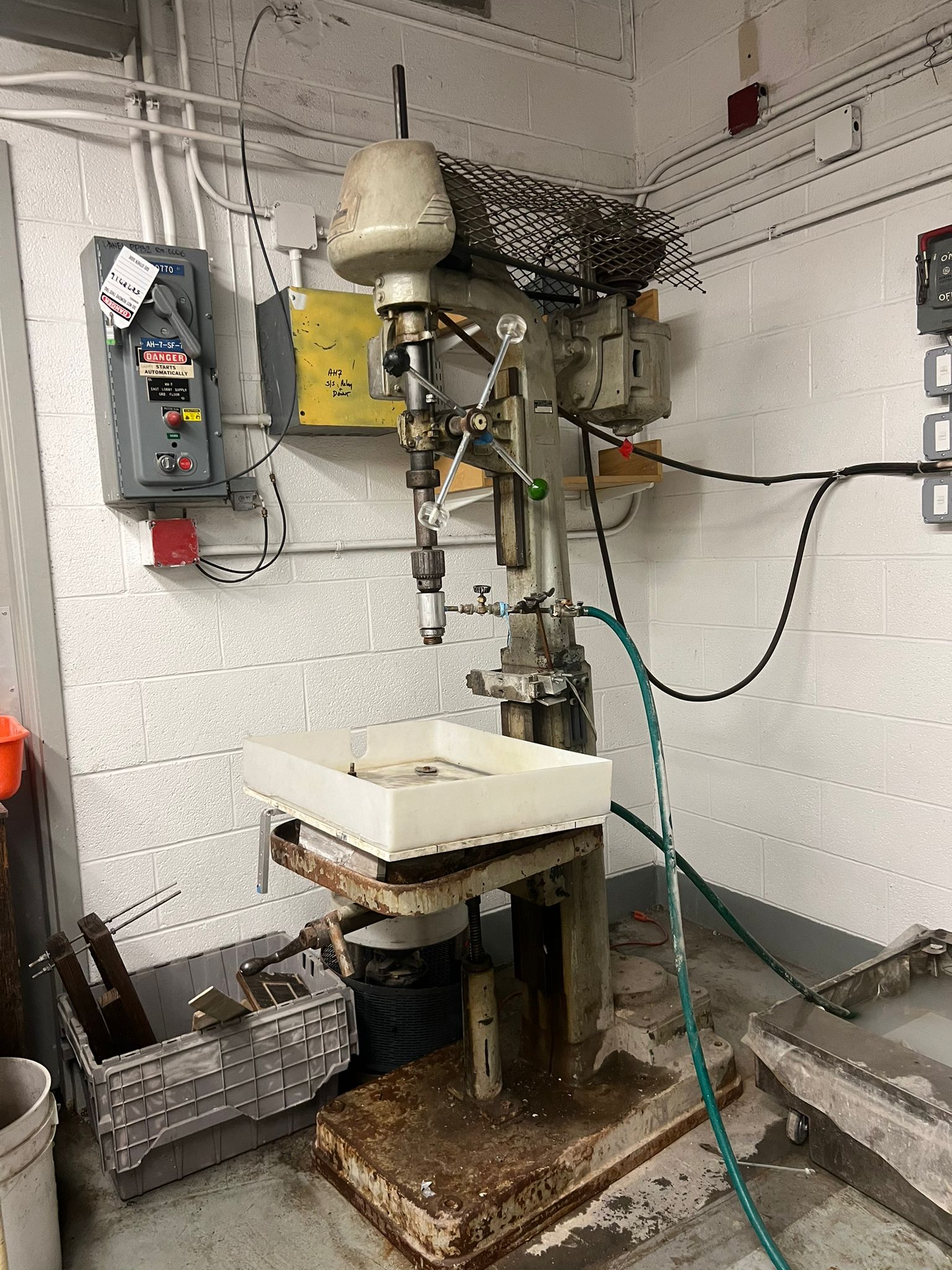
This is the powerdrill equipment with the water hose to drill the rock.
Update: December 3rd
Lately, I’ve been rethinking how to simplify and optimize my final project without overdesigning it. Initially, I considered using the camera module on the ESP32-S3 for motion detection. It worked fine, and I even tested the code by comparing pixels between previous and current frames. While the motion detection seemed to work well, I realized this wasn’t the most efficient use of the ESP32-S3. Motion sensing could be more effectively handled by the latest time-of-flight sensors, which offer features like an 8x8 multi-zone ranging grid, up to 90 degrees field of view, and greater accuracy compared to camera-based detection.
Additionally, I’m using the Raspberry Pi Pico W, which has plenty of I/O pins to handle all the tasks I currently have in mind. This led me to redesign the project to use only one microcontroller, making it simpler and more optimized.
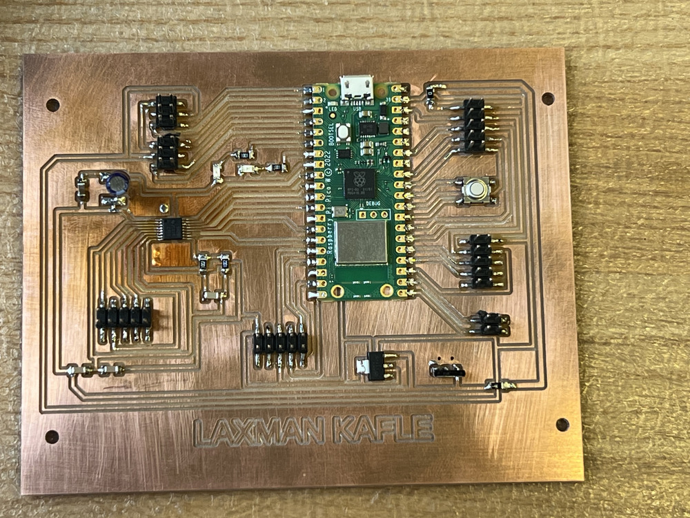
With this new approach, I designed a streamlined PCB board, milled it, and added all the necessary components.
Schematic

PCB Layout

Now the latest board looks nice and less complex with complete utilization of the pins in the Pi Pico W.
Update: December 8th
As the final week approaches, I have made significant progress to update here. This progress reflects the work done over the last few days. The most important update is that I have redesigned the eye mechanism once again, now version 5 (based on my own versioning system). I have successfully assembled it and placed it in the rock. In this new version, I have replaced the wire arms used for moving the eyelid and eyeball with 3D-printed arms. These new arms work better than the previous version, are smaller in size, and add a visually appealing touch to the design.
Currently, I envision my rock pet as a companion, somewhat like a one-eyed Minion. To complement this idea, I have also designed an eyeglass for it.
In addition to these design changes and iterations, I have been working on the base structure. I cut and assembled the base box for the rock and attached a Lazy Susan to it, which allows the rock to rotate smoothly. The updated assembly of my rock pet can be seen in the following image.
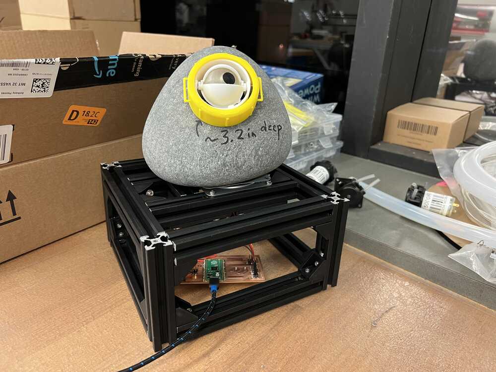
For the eye mechanism, I reused the code from my output devices week, where I had implemented basic functionalities for the weekly assignment. After placing the eye in the rock, I tested the program to make the eye move left and right and blink periodically. You can see it in action in the video below.
Update: December 9th
Today, I focused primarily on the hardware side of the project. I cut the acrylic gears and side panels, then assembled them. Additionally, I designed a small gear and printed it using the 3D printer. I also created several mounts for the servo motor, time-of-flight sensor, audio amplifier, speaker, and display to integrate them into the main box body. These mounts are now ready for 3D printing.
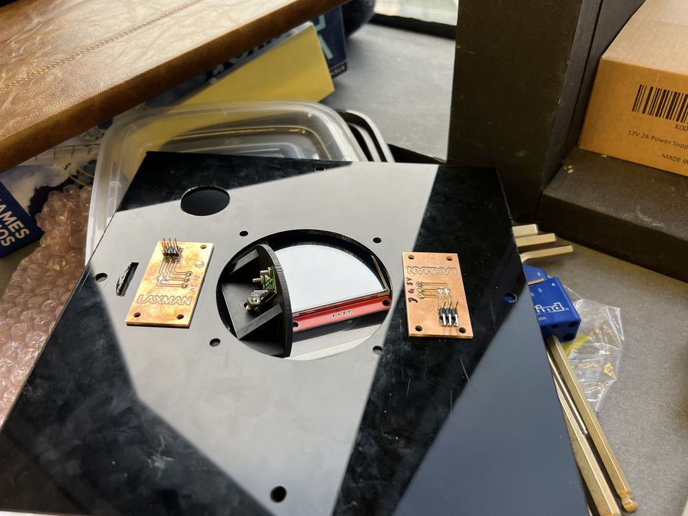
Beyond that, I had a discussion with Anthony today about how to determine the home position or where my model is oriented at the start. Anthony suggested using Hall effect sensors for this purpose. Following his advice, I designed an electronic board incorporating two Hall effect sensors positioned at the movement extremes and a magnet attached to the big gear. During initialization, the pet rock will rotate in one direction until a Hall effect sensor detects the magnet. Once the position is identified, the system will realign to a predefined home position. This ensures the rock consistently starts by facing the correct direction and prevents excessive rotations that could damage the electronics.
Update: December 10th
Although today didn’t feel like a big day for progress, I spent a significant amount of time in the lab. It seems I am approaching the final 20% of the work needed, as described by the 80-20 principle. I redesigned several components and assembled them at the base of the pet rock. Additionally, I milled the circuit board I designed yesterday for the Hall effect sensors. I now feel almost done with designing the initial spiral hardware and need to transition to the software side.
The software part intimidates me because I’m not proficient in coding, and I have several ideas that I’m unsure how to translate into code. However, I plan to begin implementing those ideas tomorrow. Alongside the coding, I will continue refining the mechanical aspects of the project. Wish me luck!
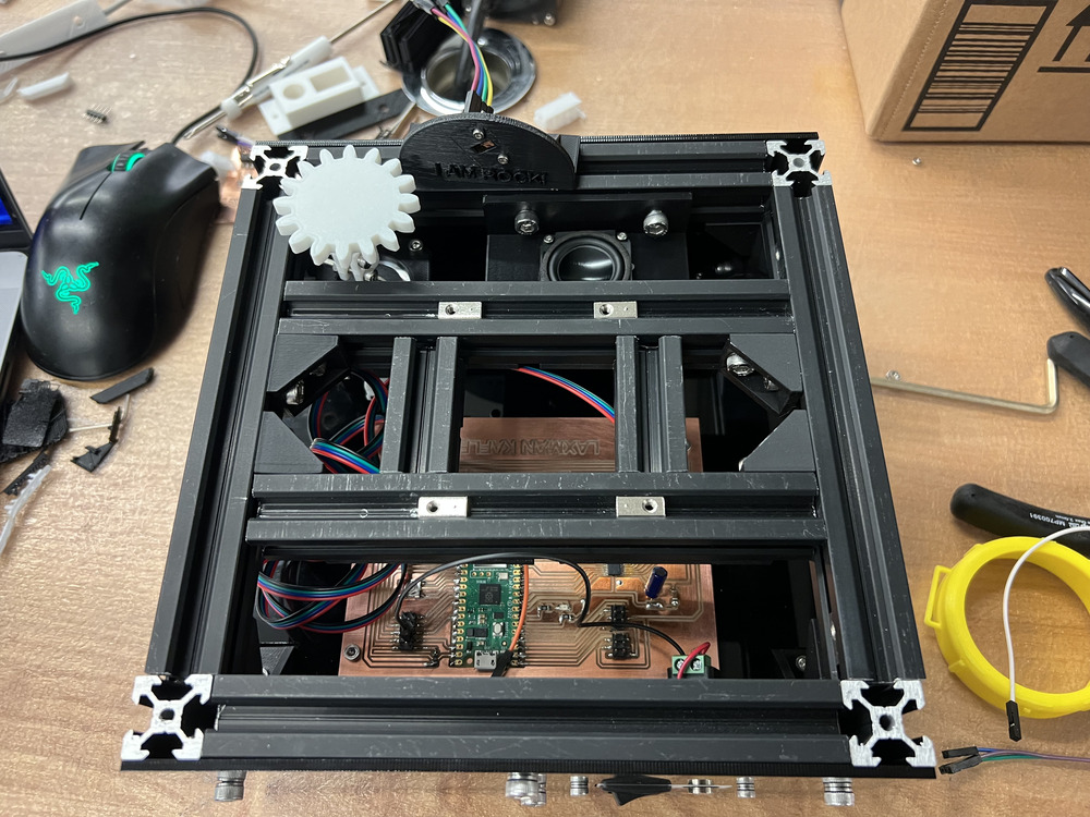
The latest assembled rock pet main control box.
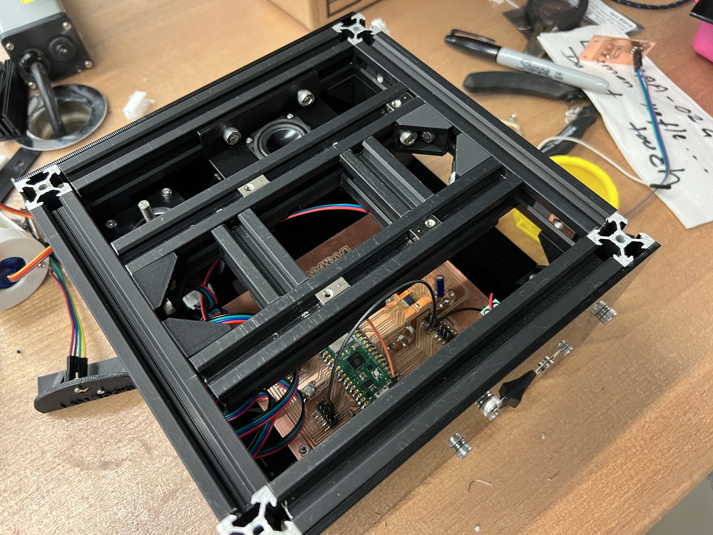
The internal structure looks very sophisticated. I think I might hold the record for using the highest number of nuts and bolts in a final project.
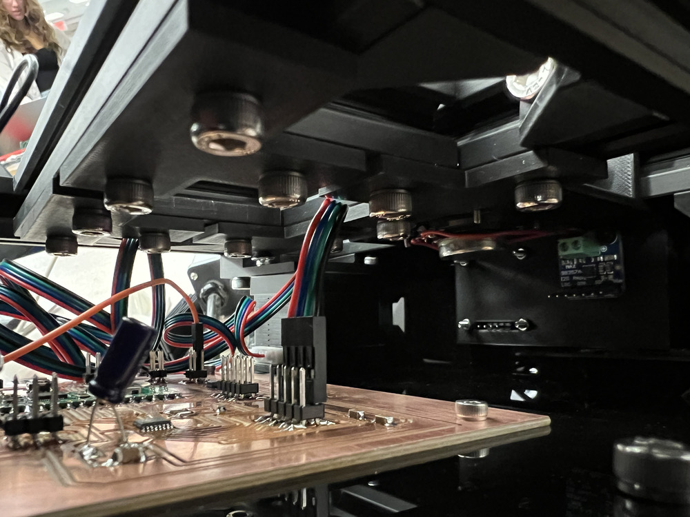
Update: December 11th
Today, we had class from 1:00 PM to 4:00 PM. I was busy earlier with assignments for another class. Luckily, I managed to finish all the final projects for those classes today. After class, I began focusing on the software and electronics aspects of the project. I haven’t yet tested all the code on my newly designed board. I started by testing simple code to blink the lights on the board. After successfully getting that to work, I wrote code for the eye mechanism, and it worked as well.
Next, I began consolidating all the code into the final project file, adding functions one by one. Once the servo motor code was functional, I moved on to testing the I2C. Unfortunately, I spent several hours at home troubleshooting the I2C code without success. I plan to ask Anthony for help tomorrow, as the I2C on my Raspberry Pi Pico isn't working as expected. Whenever I initiate I2C on GPIO pins 18 and 19, the code halts execution at the `Wire.begin()` line. I’ve used I2C successfully in the past, so this is perplexing. I even reviewed my old I2C code, which works perfectly on my previous circuit board, but not on the new one. There must be something wrong with the board, or I might be overlooking an issue.
Update: December 12th
Today, I continued working on the software side of the project. I feel like I didn’t make significant progress, but I learned a lot. I am now a firm believer in Murphy's Law—if there are ten choices to make, with one being wrong and the rest good, I always seem to pick the wrong one (or at least it feels that way)!
The bright side of today is that the I2C is now working on my new board. Anthony reviewed my code and spotted the issue in seconds. Although I spent hours troubleshooting yesterday, it turned out to be a valuable learning experience. After resolving the I2C issue, I moved on to the next task: getting the servo motor to run using the new board. Initially, the servo motor worked briefly, but then it stopped. I suspect I may have damaged some components, either on the Pico W or the motor driver, as it no longer functions.
Further troubleshooting revealed additional issues. Whenever I plug the USB into my computer, the Pico W begins overheating, even without any load. When I connect an external power supply to the board, the power control circuitry also heats up excessively. During my troubleshooting, I discovered a wiring error on the board, which could explain some of the problems. After spending hours trying to fix the board without success, I decided to remill a new board. I have finished milling the board and putting few components. I plan to completing the new board tomorrow and test the code again. Wish me luck!
By the way, here is the video of me struggling and the mess I made in the EDS at EECS at MIT.
Update: December 13th
Today’s main tasks are completed! The servo motor is up and running. I finished making the new board, and the servo motor code is now working perfectly. I can set an angle from the home position, and it rotates accordingly. I also started the final wiring for the project, made some design changes to the front and back sides of the acrylic board, and laser-cut it. Additionally, I began writing the code for motion detection. I have several ideas to try out, which I plan to tackle tomorrow.
Anthony gave me a new big LED display for my project (2.4" TFT LCD Display Touch Screen Module SPI Serial ILI9341 320x240). I’ll be using this as the front display. For the next spiral of my project development, I’m planning to integrate a calendar or reminder feature into my rock pet. This will display reminders a few minutes before they are due, both on the screen and through a speaker. I also made a circuit board for this feature today. I’ll mill the board tomorrow and start working on it. Hopefully, I can finish this part before the deadline—it’s a feature I really want to include!
December 13 update video
Update: December 14th
Today (Saturday), many things came together, and some initial integration was completed. First and foremost, I finished the motion detection algorithm, and it seems to be working. However, there is one issue: most people observing my pet rock will likely do so within a one-meter distance, and the sensor has only a 90-degree field of view. This means it can only cover about a one-meter-wide field. A human body standing close completely blocks the field of view, making it difficult for the sensor to accurately detect the direction of the most movement. Nevertheless, the motion detection is functional, which is a significant milestone.
In addition, I implemented the homing algorithm. During setup, the rock does not initially know its orientation. To address this, I installed two Hall effect sensors—one in the front and one in the back. The large gear has a single magnet, which the sensors detect. The rock determines its current position by rotating until the nearest Hall effect sensor detects the magnet. Based on the angle from that sensor’s location, it then rotates back to the home position.
Furthermore, I integrated the motion detection algorithm with the stepper motor code. This allows the rock to rotate in the direction indicated by the motion detection algorithm.
Update: December 15th
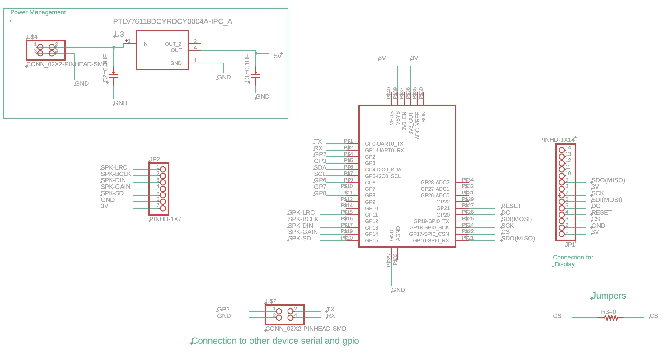
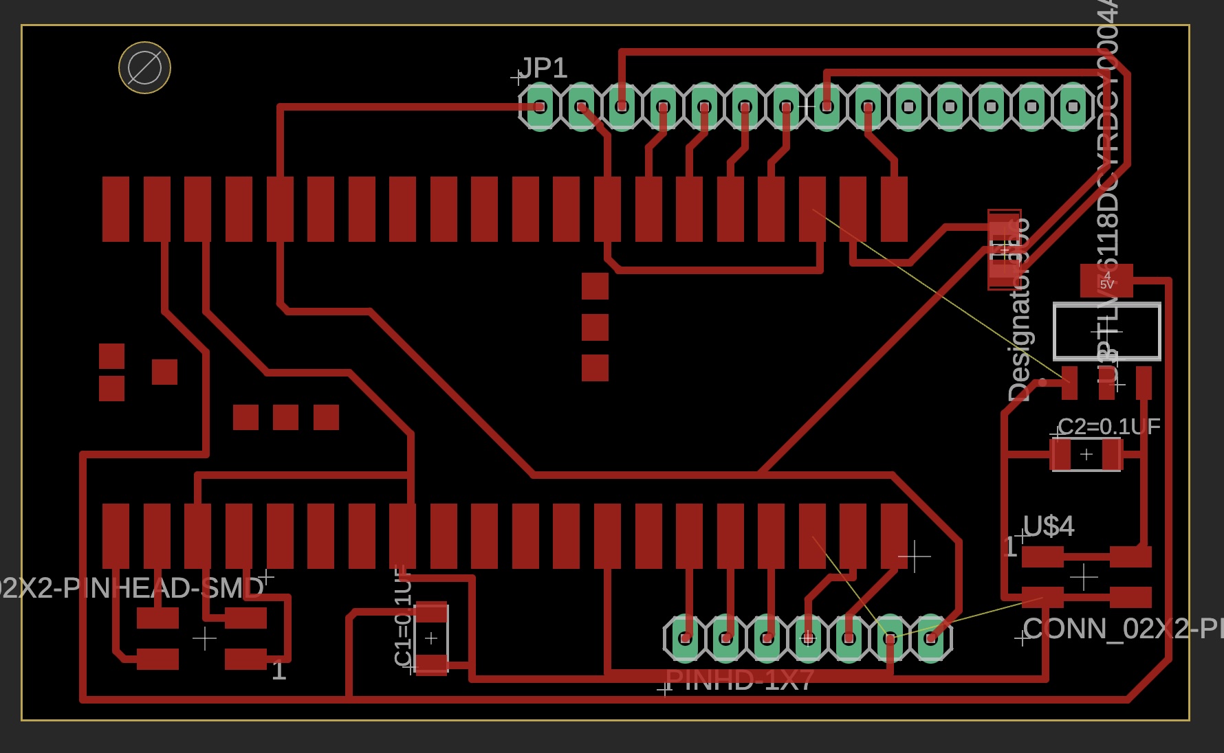
Today (Sunday), I began working on the next board, which I plan to use for the LCD screen and the speaker. I completed redesigning the board due to some previous issues, milling the board, and soldering the components onto it.
Schematic
PCB
After soldering, I tested the display by showing some simple text on the screen using example code I found online. It worked perfectly.
Update: December 16th
Today marks the final day of the project and class work. I had almost completed most of the tasks yesterday, with the speaker being the only remaining issue. Fortunately, I managed to fix it within the first hour. After that, my focus was on integrating all components so that they work seamlessly together to perform the desired task.
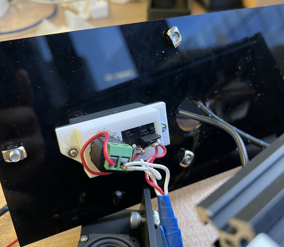
Here, I will also document everything I have done so far, including any details I might have missed in previous updates. Since I am using several sensors, a stepper motor, and multiple servo motors, the current provided by USB is insufficient. To address this, I designed an external power source for both microcontrollers. You can see the internal power connections in the image below:
I am using Hall effect sensors to detect the rock's position when it starts. I believe I mentioned this earlier but did not include a picture of the board. Here it is now:
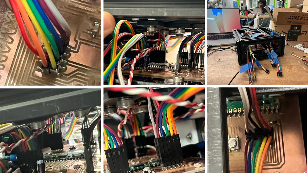
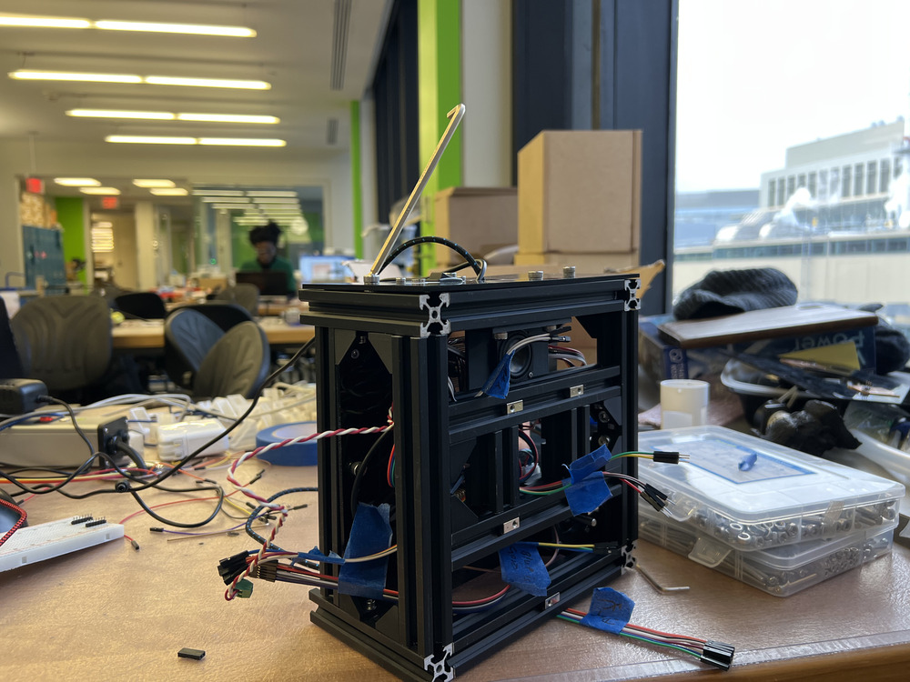
Assembling everything was incredibly satisfying, especially working with aluminum extrusions. You can see several wires sticking out from the two boards inside the box. These wires will be hidden behind an acrylic panel once the assembly is complete.
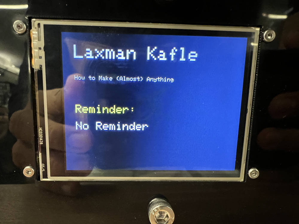
I am using an LCD display to show the project name and also as a feature to display tasks or reminders. This display communicates with the Pico microcontroller via SPI communication, which was straightforward to implement. However, there was a noticeable lag between frames, which was quite annoying. I solved this issue by refreshing only the part of the display that required updating.
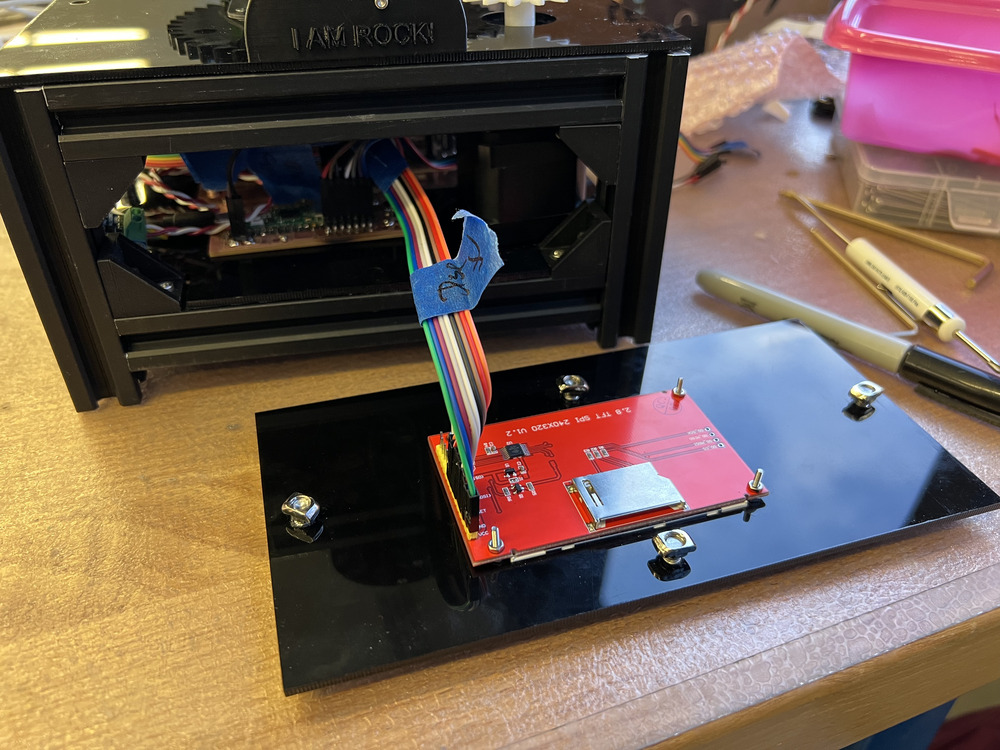
In the two images below, you can see the LCD screen in action:
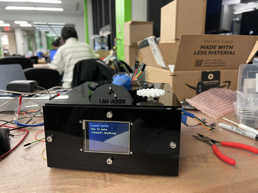
Close-up view of the LCD screen:
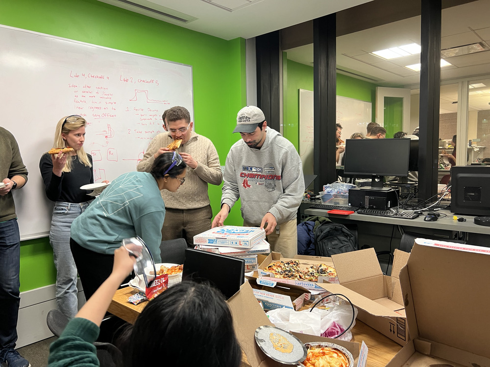
On a late Monday night, everyone was working tirelessly, and Anthony treated us with pizza. Who doesn’t love pizza?!
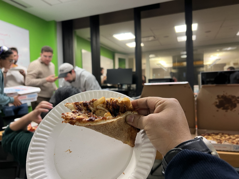
Here’s everyone enjoying the late-night pizza:
Today I made the sound system working in my pet rock. See the video below to how it is working and with the time of flight sensor.
Before coming home I made a quick video of my rock pet working to have evideance to show if something goes wrong and to say it was working until yesterday.
Update: December 17th
Today was the final presentation day. I transported the Rock Pet in a cardboard box to the Media Lab.
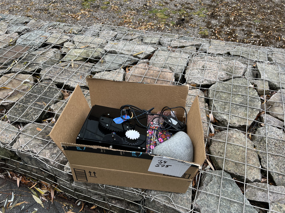
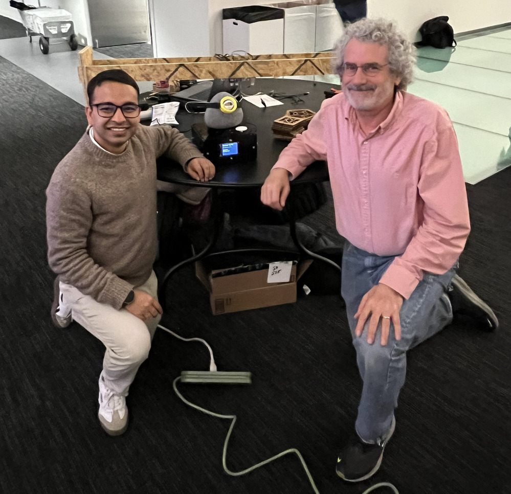
The presentation went really well, and everyone loved my Rock Pet. Neil was especially excited to see that I successfully drilled the rock. Below, you can see two happy people with the most adorable rock in the entire universe.
Future Improvements
Due to time constraints, I was unable to include the following features in my final project:
- Integration of a Calendar API
- Smoother motion detection
- Better-sized rock with two eyes
- Memory slot for pre-recorded reminder sounds
- Touch capability on the LCD screen to add new reminders or alarms
- Improved eye mechanism
Files for Future Replication
Download the following files for CAD designs, PCB layouts, and Arduino code to replicate the project:
- Full Assembly: Fusion 360 .step file
- Latest Eye Mechanism: Fusion 360 .step file
- Minion Goggle: Fusion 360 .step file
- Main Pico Board: Fusion 360 .f3z file
- Second Pico Board (for Display and Audio): Fusion 360 .f3z file
- Hall Effect Sensor Board: Fusion 360 .f3z file
- Arduino Code for Main Board: Arduino code
- Arduino Code for Second Pico: Arduino code