                                #include <SPI.h>
                                #include <Wire.h>
                                #include <Adafruit_MAX31855.h>
                                #include <Adafruit_GFX.h>
                                #include <Adafruit_SSD1306.h>

                                // Define MAX31855 pins
                                #define MAXDO   13       // Data Out pin
                                #define MAXCS   14       // Chip Select pin
                                #define MAXCLK  15       // Clock pin

                                // Initialize the thermocouple instance with software SPI
                                Adafruit_MAX31855 thermocouple(MAXCLK, MAXCS, MAXDO);

                                // OLED display dimensions
                                #define SCREEN_WIDTH 128
                                #define SCREEN_HEIGHT 64

                                // Create an SSD1306 display object connected to I2C
                                Adafruit_SSD1306 display(SCREEN_WIDTH, SCREEN_HEIGHT, &Wire1, -1);

                                void setup() {
                                // Initialize Serial for debugging
                                Serial.begin(9600);

                                // Initialize I2C for the display with custom pins
                                Wire1.setSDA(10);         // Set custom SDA pin
                                Wire1.setSCL(11);         // Set custom SCL pin
                                Wire1.begin();            // Start I2C with custom pins

                                Serial.println("Initializing MAX31855...");

                                // Initialize the thermocouple sensor
                                delay(500); // Delay for sensor stability
                                if (!thermocouple.begin()) {
                                    Serial.println("ERROR: MAX31855 not detected.");
                                    while (1) delay(10); // Halt if initialization fails
                                }

                                // Initialize the OLED display with the correct address
                                if (!display.begin(SSD1306_SWITCHCAPVCC, 0x3C)) { // Check for address 0x3C
                                    Serial.println("ERROR: SSD1306 allocation failed.");
                                    for(;;); // Halt if display initialization fails
                                }

                                Serial.println("Initialization successful.");
                                }

                                void loop() {
                                // Read the temperature in Celsius from the thermocouple
                                double celsius = thermocouple.readCelsius();
                                double fahrenheit = celsius * 9.0 / 5.0 + 32.0;  // Convert Celsius to Fahrenheit

                                // Clear previous content from the display buffer
                                display.clearDisplay();
                                display.setTextSize(2);          // Set text size (1 is small, readable)
                                display.setTextColor(SSD1306_WHITE); // Set text color to white
                                display.setCursor(0, 0);         // Start writing at top-left corner

                                if (isnan(celsius)) {
                                    // Handle errors if temperature data isn't available
                                    Serial.println("Thermocouple fault(s) detected!");
                                    display.println("Thermocouple fault!");

                                    uint8_t error = thermocouple.readError();
                                    if (error & MAX31855_FAULT_OPEN) {
                                    Serial.println("FAULT: Open connection.");
                                    display.println("FAULT: Open.");
                                    }
                                    if (error & MAX31855_FAULT_SHORT_GND) {
                                    Serial.println("FAULT: Short to GND.");
                                    display.println("FAULT: Short to GND.");
                                    }
                                    if (error & MAX31855_FAULT_SHORT_VCC) {
                                    Serial.println("FAULT: Short to VCC.");
                                    display.println("FAULT: Short to VCC.");
                                    }
                                } else {
                                    // Display temperature in the format: "T = xx °C || xx °F"
                                    Serial.print("T = ");
                                    Serial.print(celsius);
                                    Serial.print(" °C || ");
                                    Serial.print(fahrenheit);
                                    Serial.println(" °F");

                                    display.print("T = ");
                                    display.print(celsius);
                                    display.print(" C || ");
                                    display.print(fahrenheit);
                                    display.println(" F");
                                }

                                // Render content to OLED
                                display.display();
                                delay(1000); // Delay for readability and sensor stability
                                }
Week 8: Input Devices
We in the EECS group started our week with our usual, extremely useful walkthrough by Anthony. This week focused on soldering using the reflow technique.
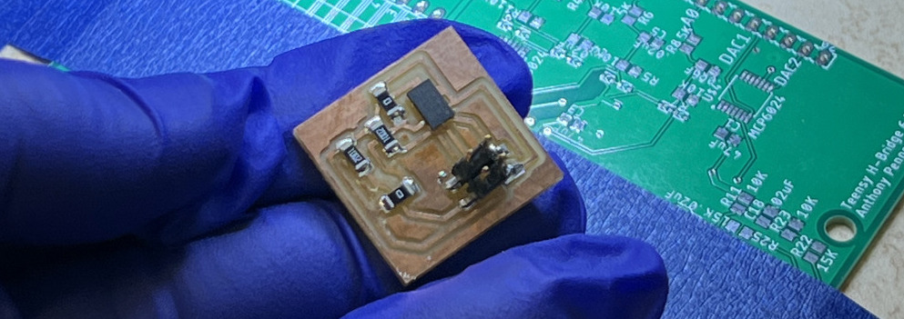
Anthony explained everything clearly and demonstrated how to make (almost) perfect joints using reflow. Then, we got the chance to try it on our own. You can see the result of my first reflow test below.
Now, onto the assignment. This week's task is to measure something by adding a sensor to a microcontroller board we previously designed and then read data from it.
This week sounded fun, and I wanted to try a lot of different input devices, from a camera module, distance sensors, and audio input to acoustic wave sensors, temperature sensors, and other transducers. But unfortunately, I couldn’t give my 100% to HTMAA this week because I had my general exam Part II on Thursday and was fully packed on Friday. I usually spend Saturday as my creative day, brainstorming fun ideas for assignments. However, this weekend I was sick and couldn't give my best.
Despite losing a few days, I tried to test as many input devices as possible. My first idea was to read and display temperature from the thermocouple I use in my experiments. The second was to work with a displacement sensor, and the third was to test the camera sensor on the ESP32S3, which I need for my final project.
Project 1: Thermocouple
I wanted to use a sensor relevant to my research, so I chose a thermocouple. In a recent experiment, I used a thermocouple to heat a sample up to 250°C over two hours, starting from room temperature. Once it reached 250°C, I held it there for 30 minutes to ensure temperature stability. This setup involved a feedback control system with the thermocouple for sensing, a heating band, and a temperature controller from COL-INT TECH. While the device had a small LED screen to show target and current temperatures, it couldn’t record data directly into the data acquisition system. Adding this feature felt perfect for this week’s project.
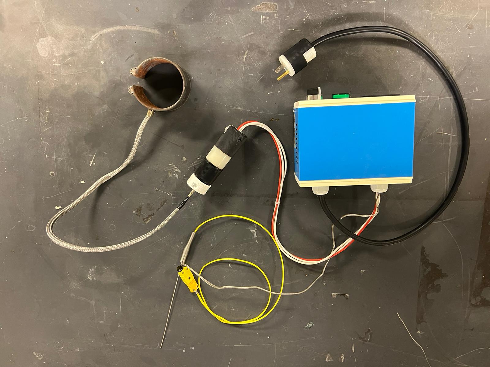
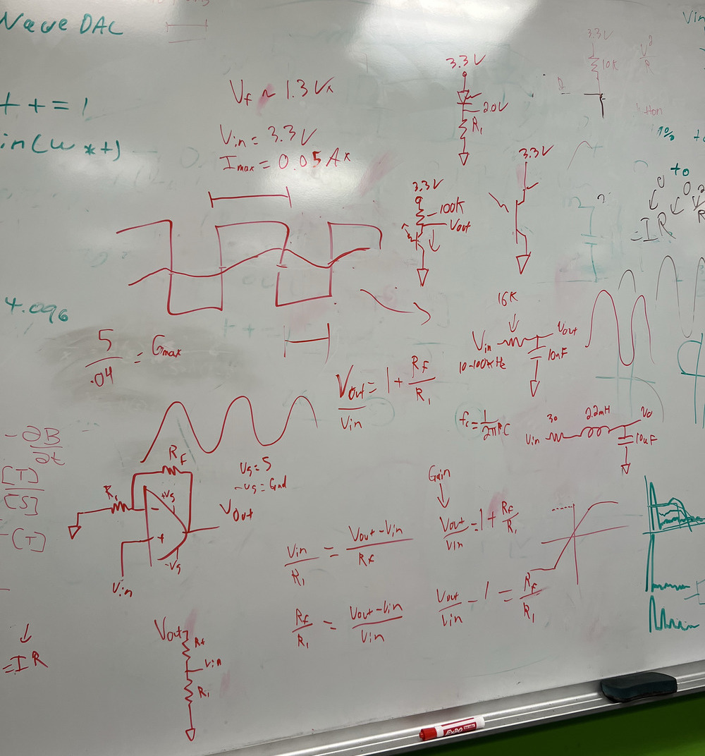
My first step was understanding the thermocouple's output and splitting the signal to feed both the data acquisition system and the temperature controller. With Anthony’s guidance, I designed the circuit board. He explained how different components, like op-amps, pull-up resistors, and resistor-capacitor combos, work together to convert digital signals to analog.
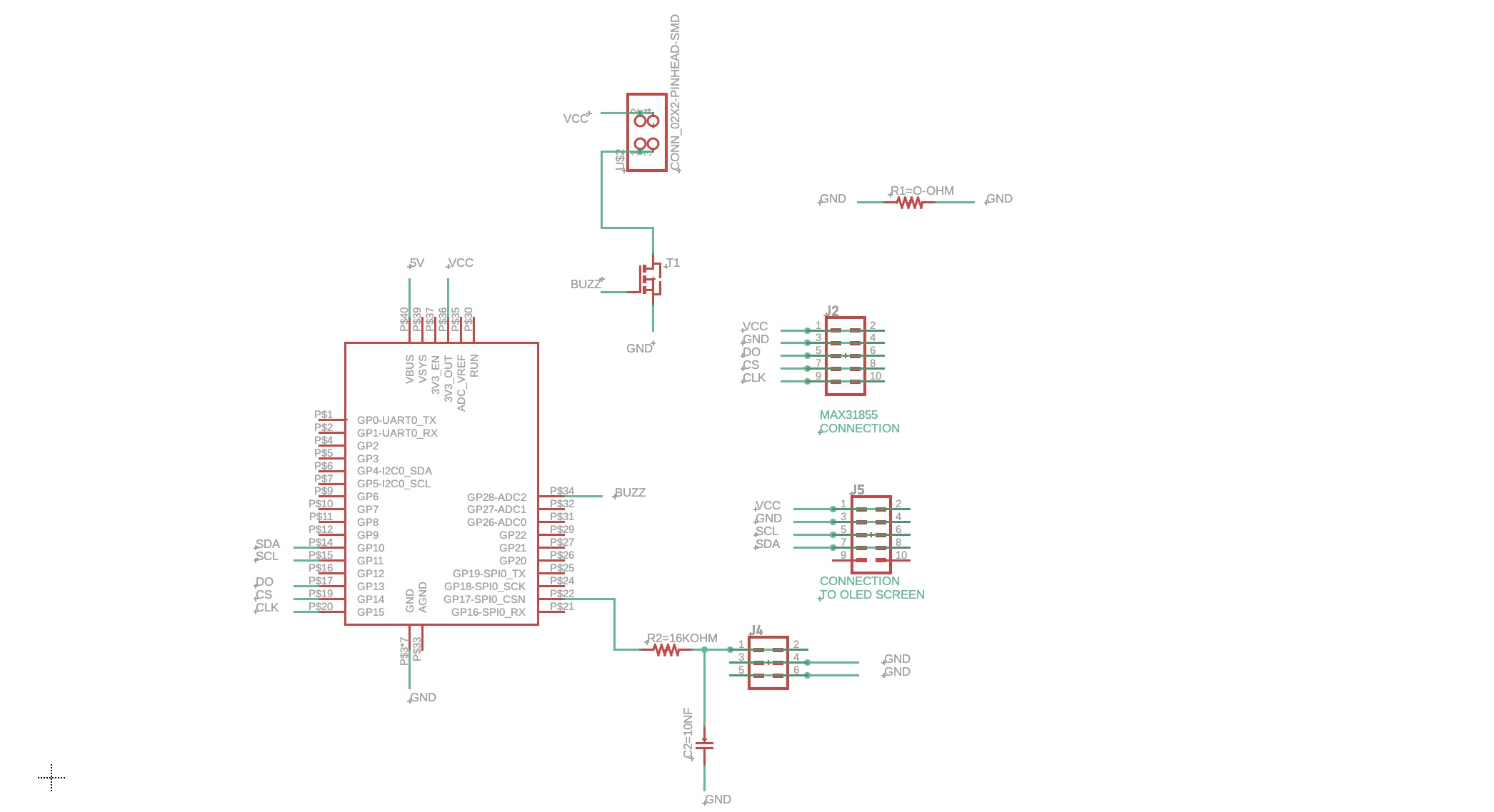
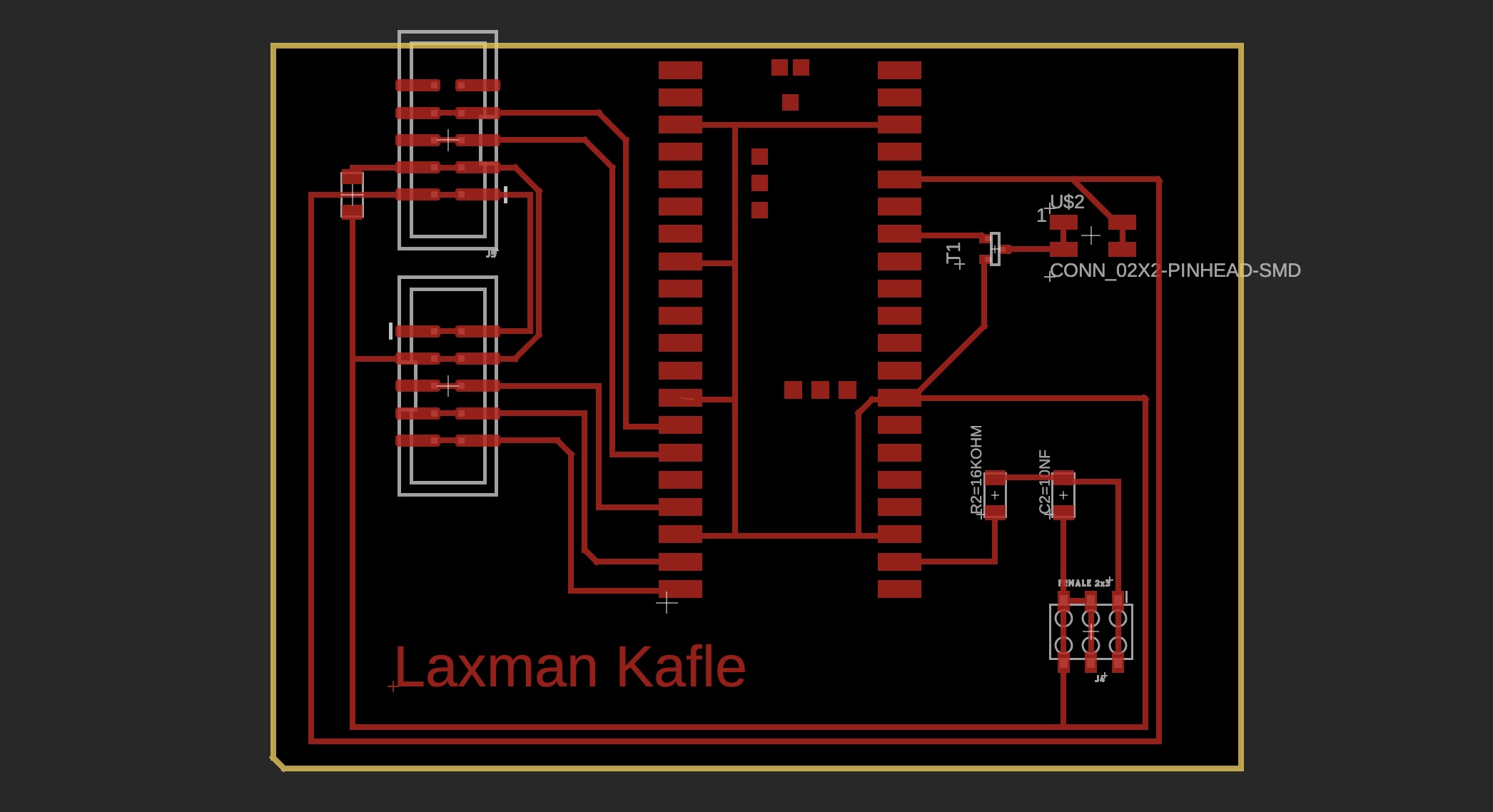
Here’s the design of my board:
Schamatic
PCB Layout
For this project, I needed several components:
- Raspberry Pi Pico W
- Thermocouple (from my lab)
- MAX31855 (for analog-to-digital conversion and cold-junction compensation)
- LED display
- Other components like resistors, capacitors, and connection pins
My goal was not just to read the thermocouple’s output but also to connect this system to the lab’s data acquisition system. This way, I could record temperature alongside other experimental data, allowing me to relate temperature changes to other measurements.
The MAX31855 took a while to arrive from Amazon, so I worked on other sensors in the meantime. Once it arrived, I connected all the parts to test them, but of course, it didn’t work on the first try. The Pico W wouldn’t boot, likely because I had reused it from a previous project, where I’d removed it with a hot air gun. There’s a good chance I fried it in the process.
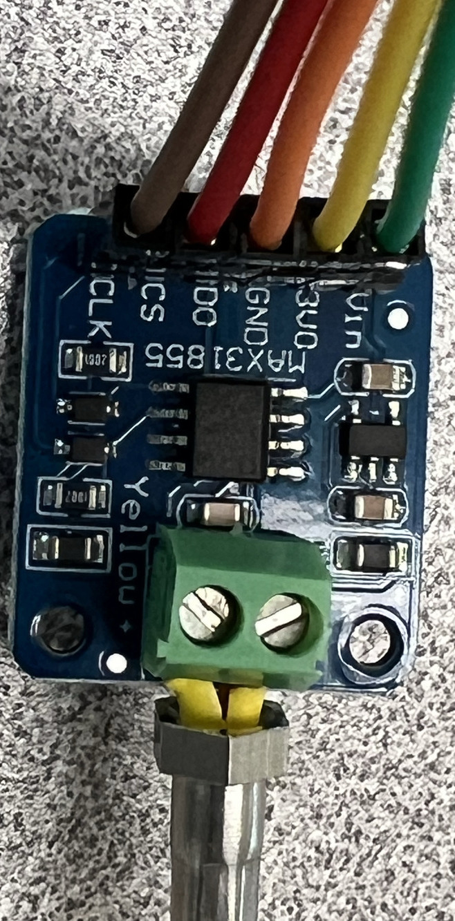
A closer look at the MAX31855 breakout board:
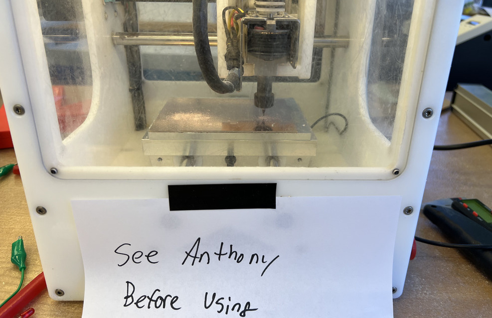
After hours of troubleshooting, I decided to make a new board. Unfortunately, the milling machine was having issues, especially with the Z-axis setting for the milling bit. Anthony temporarily fixed this with a jumper cable workaround.
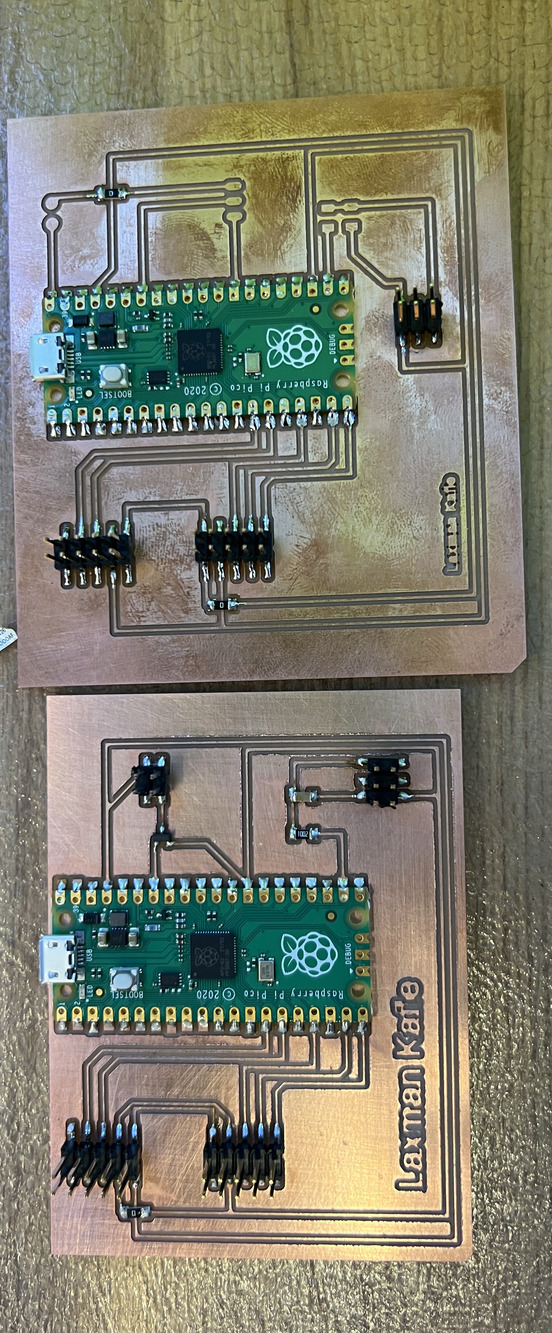
I modified the board design a bit, as you can see on the left. After soldering, everything looked promising.
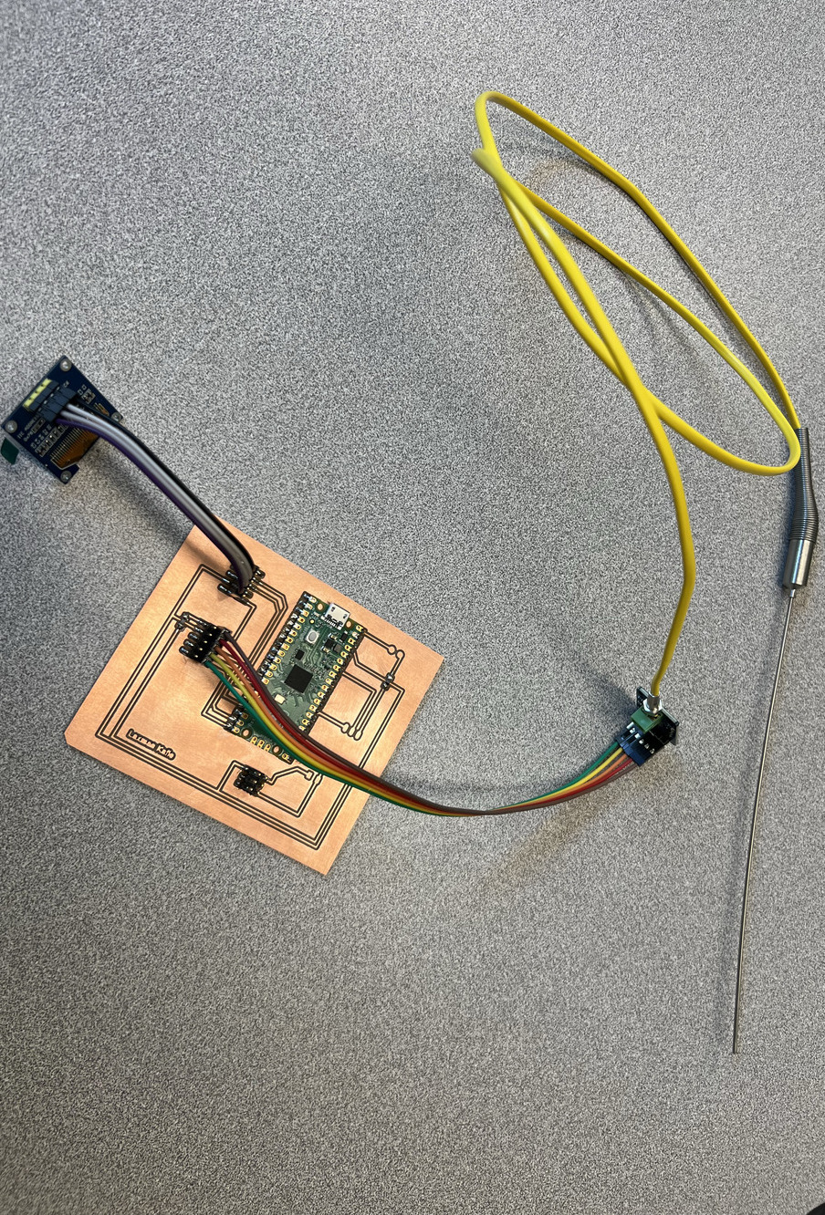
It’s working! I rewrote some code and got it running. I attached an OLED display. The data acquisition and buzzer part I am not doign this time.
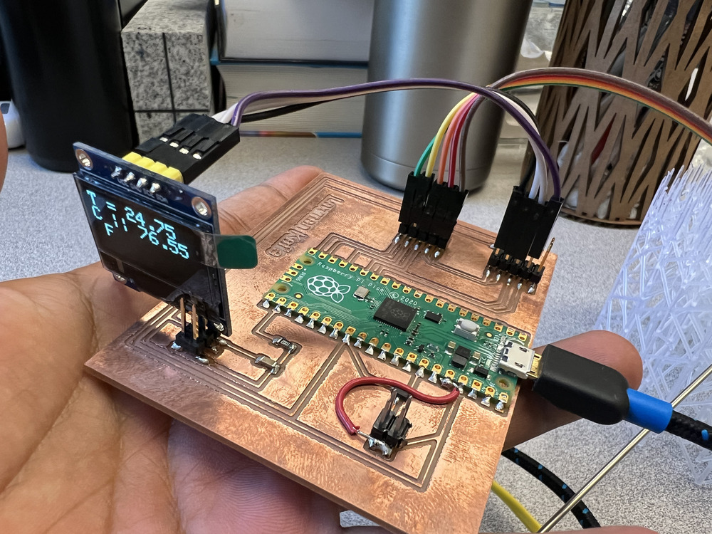
This is the complete setup for my temperature sensor project—it’s been quite a journey, and I even worked on this during week 9.
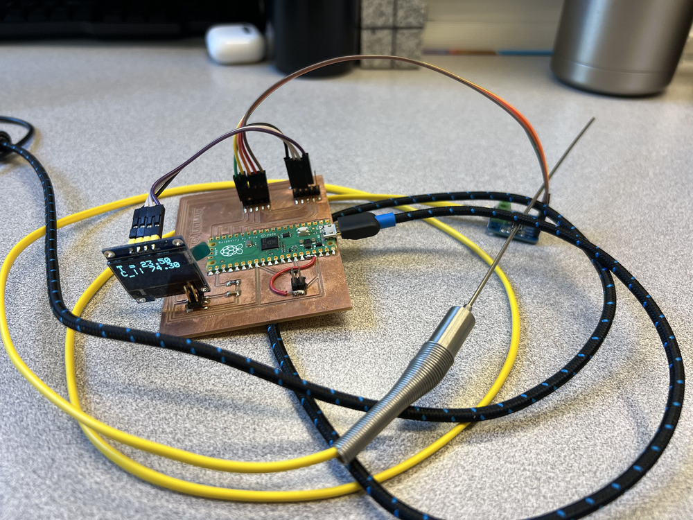
Now, everything is running smoothly. Feel free to try making the temperature sensor yourself! The PCB design is updated and ready for use with the Pico.
Project 2: Distance Measurement
Distance measurement is a key parameter in my experiments. I've used larger laser sensors and strain gauges before, but I hadn’t tried these tiny, calibrated distance sensors. Typically, we use pre-calibrated sensors that connect directly to the data acquisition system, so there’s no coding beyond understanding basic parameters.
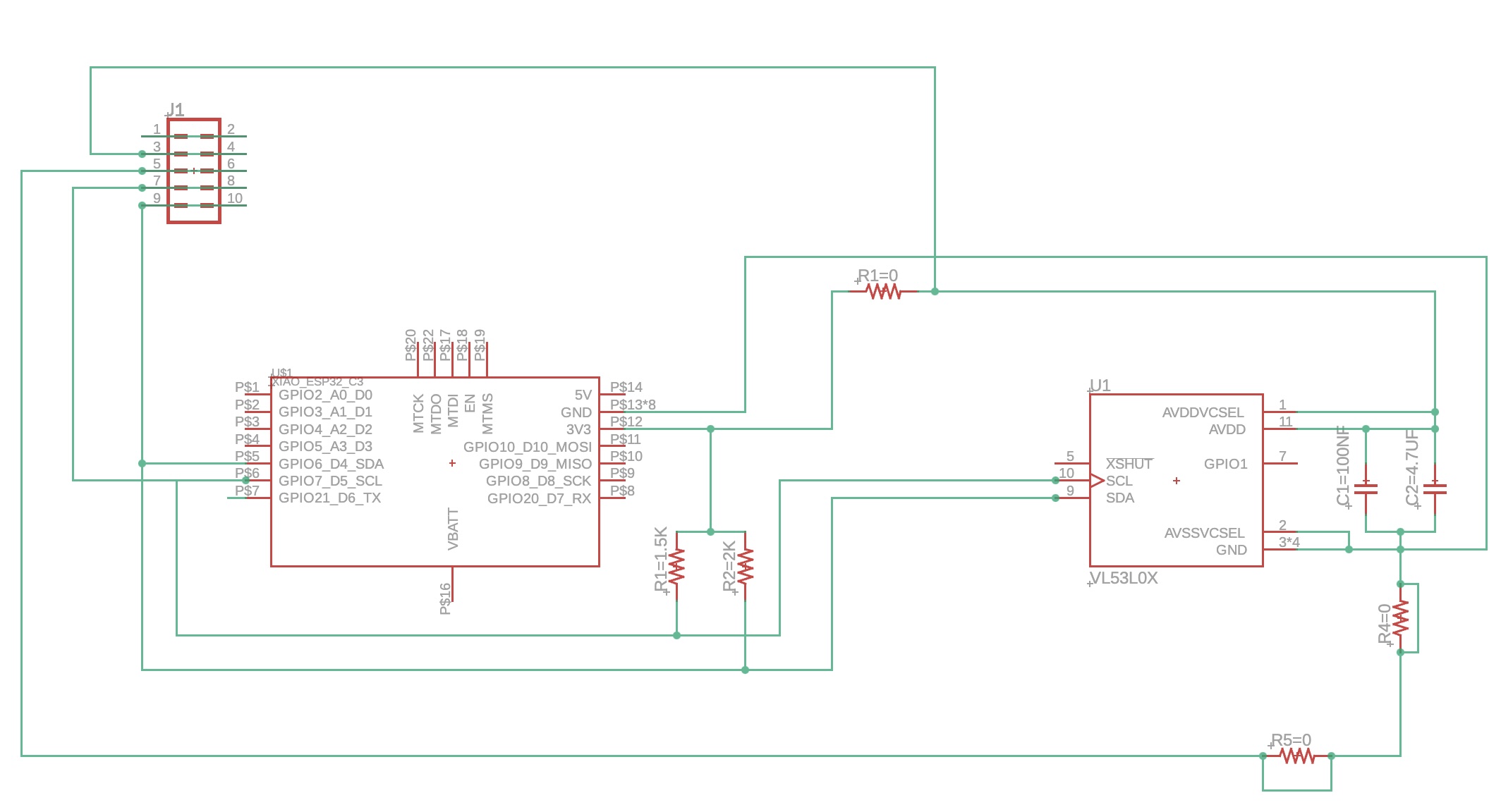
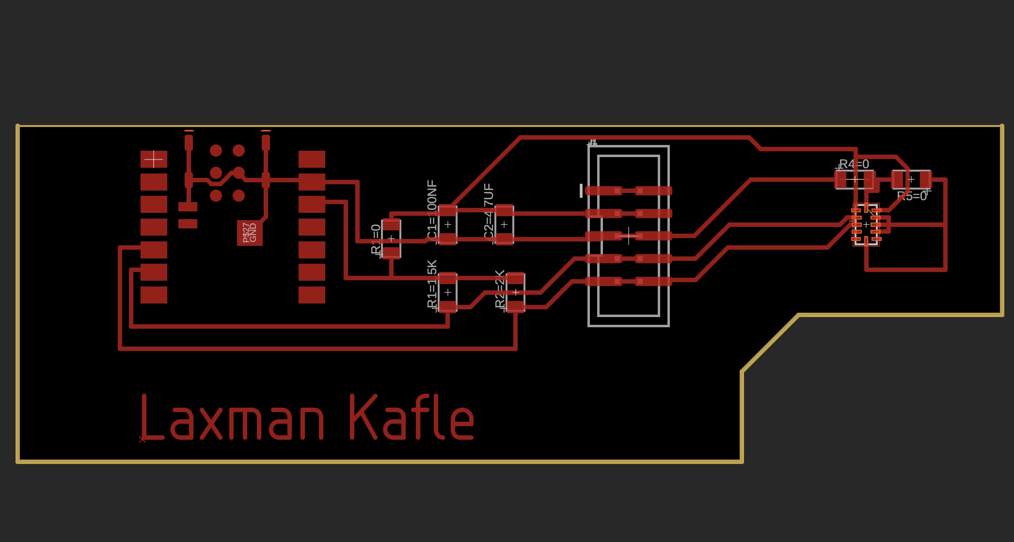
Anthony provided me with VL53L0X sensors—tiny laser-based distance sensors. I designed the circuit board and connected everything. This board is straightforward, with an ESP32C3 microcontroller, a five-pin connector for an LED screen to display the distance, and the VL53L0X sensor. First, I read the datasheet carefully, which explained the need for pull-up resistors and capacitors, so I designed and milled the circuit board accordingly.
Schamatic
PCB Layout
After soldering, I began coding based on class notes with some tweaks, but the sensor didn’t initialize. At this point, I added the LED screen to display the measured distance.
Frustration kicked in! My Pico board for the temperature sensor wasn’t cooperating, and the distance board wasn’t recognizing the sensor. Ah, the joys of electronics, haha!
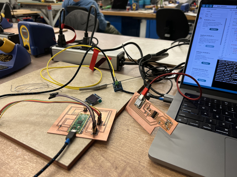
The LED display was working fine, so I got a head start on week 9's assignment. Now, my job is to read the sensor’s data and display it on the LED screen, which is already set up.
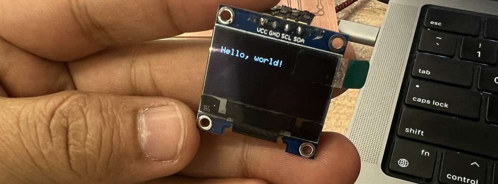
Despite my microcontroller not communicating with the VL53L0X sensor, it displayed a reading of 65535 mm, likely a default value caused by the input voltage, which the microcontroller mistakenly read as sensor data.

Anthony, Sam, Alec, and I tried every troubleshooting trick we knew, but the issue persisted.
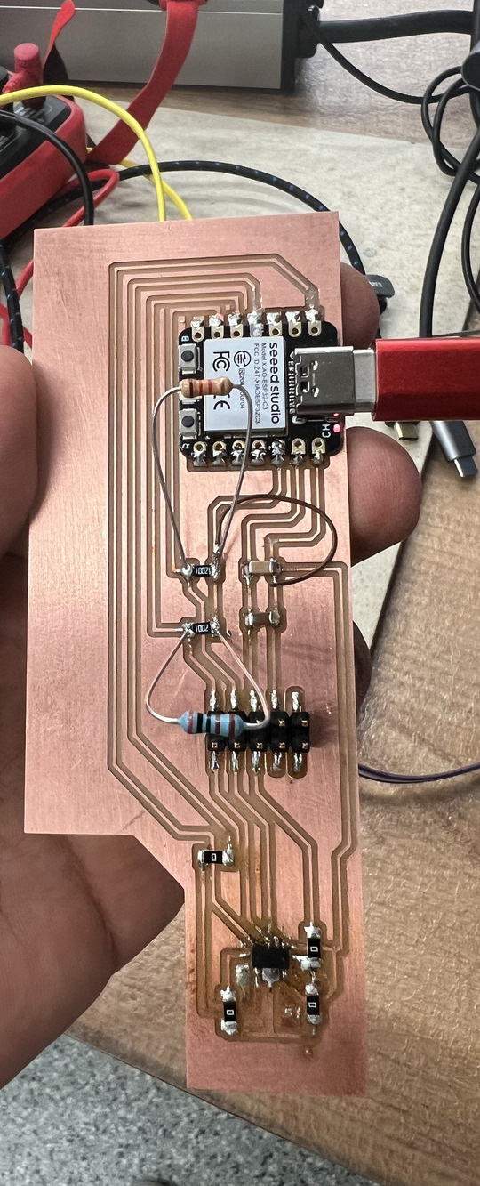
This is the board giving me trouble! I tried multiple debugging techniques, checked the soldering on the tiny VL53L0X sensor, tested the wiring, and even used jumper wires, but nothing seemed to work.
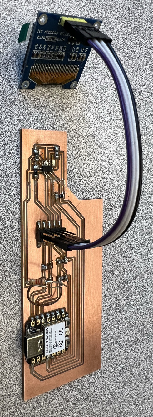
After hours of debugging, I decided to start fresh with a new board and a new sensor. Anthony also gave me a VL53L0X sensor on a breakout board, which didn't require soldering.
Below, you can see the new board side-by-side with the old one for comparison. Still, the problem persisted on the new board.
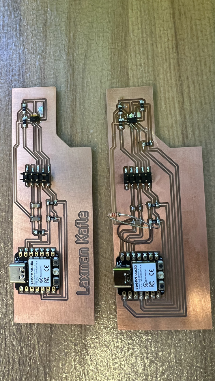
Initially, I suspected poor soldering on the tiny sensor, which I had reflowed to attach. After extensive debugging, we figured the problem likely stemmed from imperfect soldering between the PCB and the sensor.
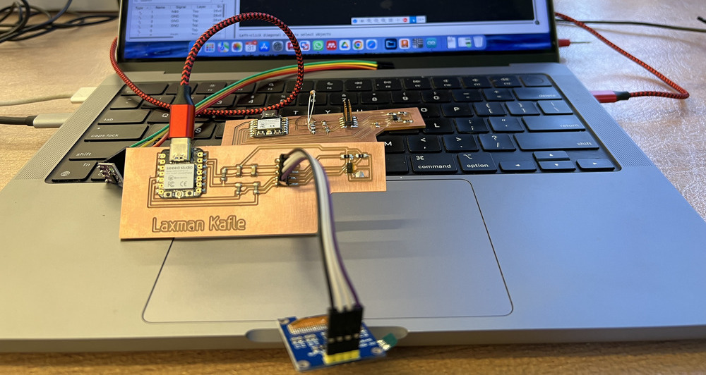
Even after solving the power issue, the board still didn’t work. So, I used the VL53L0X breakout board, which—bingo!—worked perfectly. We checked the accuracy by comparing the laser-measured distance with a tape measure, and it was spot-on.
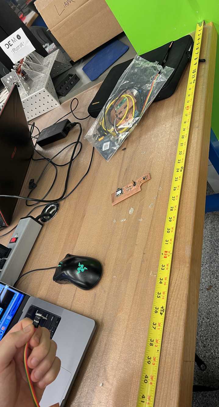
The distance measurement project had a happy ending, and it’s working fine. Hurray!!!
I also connected the OLED display to show the distance.
                            #include <Wire.h>
                            #include <VL53L0X.h>
                            #include <Adafruit_GFX.h>
                            #include <Adafruit_SSD1306.h>

                            #define SCREEN_WIDTH 128  // OLED display width, in pixels
                            #define SCREEN_HEIGHT 64  // OLED display height, in pixels
                            #define OLED_RESET    -1   // Reset pin (-1 if sharing Arduino reset pin)
                            #define SCREEN_ADDRESS 0x3C  // I2C address for OLED, typically 0x3C or 0x3D

                            // Initialize the VL53L0X sensor
                            VL53L0X sensor;

                            // Initialize the OLED display
                            Adafruit_SSD1306 display(SCREEN_WIDTH, SCREEN_HEIGHT, &Wire, OLED_RESET);

                            void setup() {
                            Serial.begin(9600);
                            Wire.begin();

                            // Initialize OLED display
                            if(!display.begin(SSD1306_SWITCHCAPVCC, SCREEN_ADDRESS)) {
                                Serial.println(F("SSD1306 allocation failed"));
                                while(1);  // Loop forever if OLED init fails
                            }
                            display.clearDisplay();
                            display.setTextSize(1);
                            display.setTextColor(SSD1306_WHITE);
                            display.setCursor(0, 0);
                            display.println("Distance:");
                            display.display();

                            // Initialize the VL53L0X sensor
                            Serial.println("Initializing sensor...");
                            sensor.setTimeout(500);
                            if (!sensor.init()) {
                                Serial.println("Failed to detect and initialize sensor!");
                                display.setCursor(0, 20);
                                display.println("Sensor failed!");
                                display.display();
                                while (1);  // Halt on error
                            }

                            // Optional sensor modes
                            #if defined LONG_RANGE
                                sensor.setSignalRateLimit(0.1);
                                sensor.setVcselPulsePeriod(VL53L0X::VcselPeriodPreRange, 18);
                                sensor.setVcselPulsePeriod(VL53L0X::VcselPeriodFinalRange, 14);
                            #endif

                            #if defined HIGH_SPEED
                                sensor.setMeasurementTimingBudget(20000);  // Timing budget to 20ms
                            #elif defined HIGH_ACCURACY
                                sensor.setMeasurementTimingBudget(200000); // Timing budget to 200ms
                            #endif
                            }

                            void loop() {
                            int distance = sensor.readRangeSingleMillimeters();

                            // Print distance to serial monitor
                            Serial.print("Distance: ");
                            Serial.print(distance);
                            Serial.println(" mm");

                            // Display distance on OLED
                            display.clearDisplay();
                            display.setCursor(0, 0);
                            display.println("Distance:");
                            display.setCursor(0, 20);

                            if (sensor.timeoutOccurred()) {
                                Serial.println(" TIMEOUT");
                                display.println("TIMEOUT");
                            } else {
                                display.print(distance);
                                display.println(" mm");
                            }

                            display.display();  // Show on OLED
                            delay(500);         // Adjust delay as needed
                            }
Project 3: Camera Module
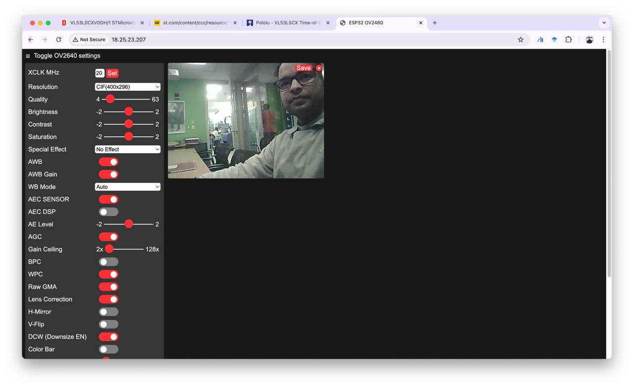
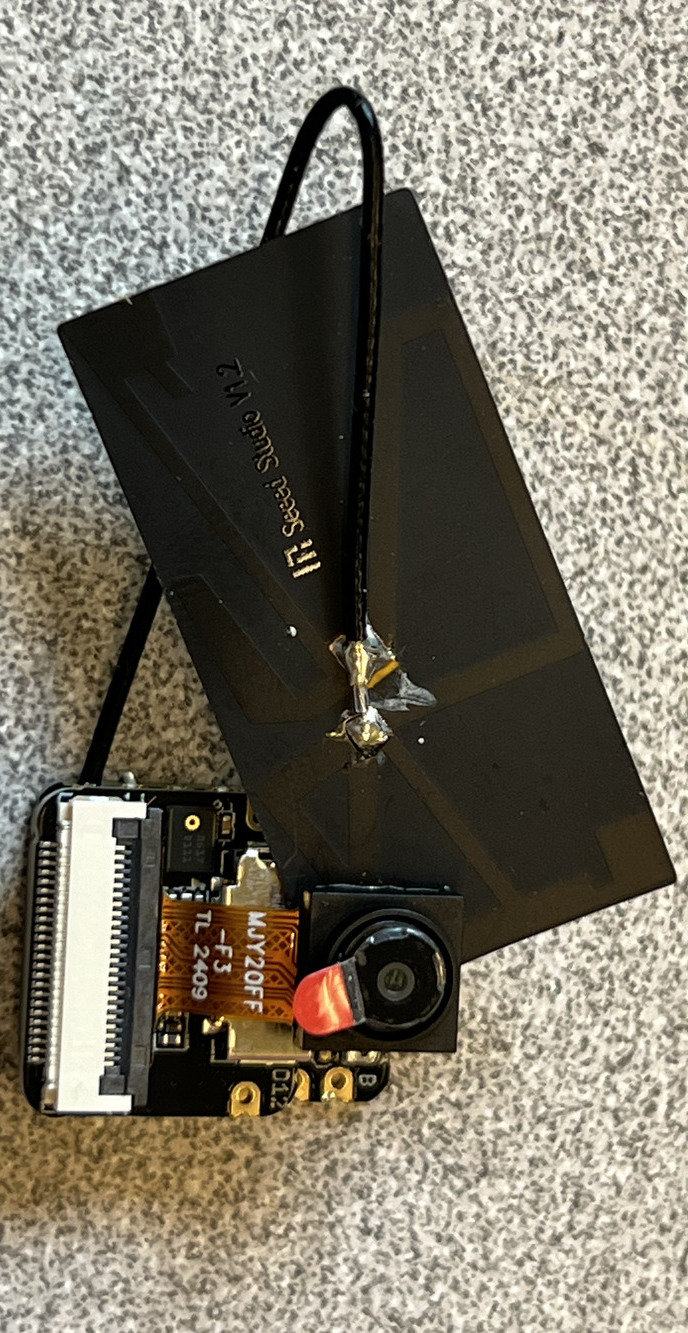
I wanted to experiment with the camera module as an initial step for my final project and as part of this week's assignment. The camera module connects directly to the ESP32S3, so there was no need to design a separate circuit board. I had an ESP32S3 on hand, but spent hours troubleshooting because the connection with the camera module wasn’t working. After seeing my struggle, Anthony took me to the CBA lab to grab an ESP32S3 from their inventory, which worked perfectly!
