Project: PCB Piano
This week focused on electronics design. We explored KiCad, EAGLE in Fusion 360, and Leo's tool, SVG-PCB. Based on Anthony's recommendation, I opted to go with Fusion 360 for this project.
My ultimate goal is to create a piano-playing robot, but for now, I wanted to design a synthesizer. I wanted a design which incorporated selectors for different waveforms, knobs to adjust ADSR parameters, and speaker output. Traditional analog synthesizers (like the Moog) use VCOs to generate waveforms, but I wanted to take a digital approach using a microcontroller with DAC outputs.
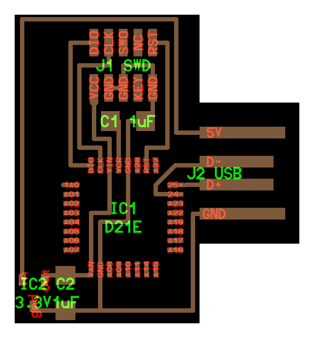
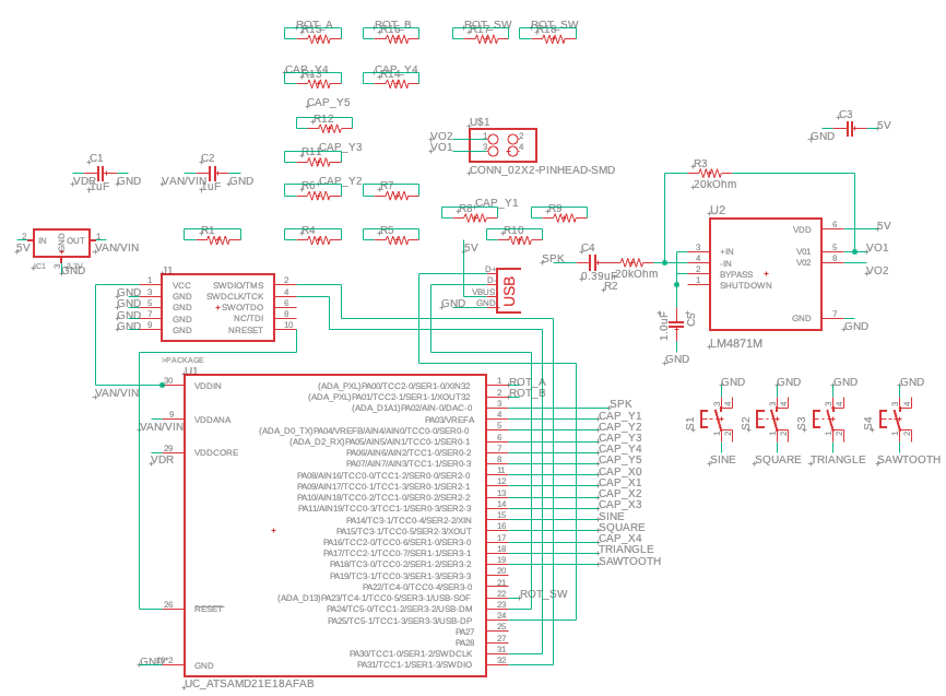
The SAMD21E17A microcontroller was a perfect fit for this project, as it offers a 10-bit DAC output at 350 kbps and plenty of GPIOs. I wired the SAMD21E with a JTAG and USB port based on the circuit diagram from Lecture 3, shown below:
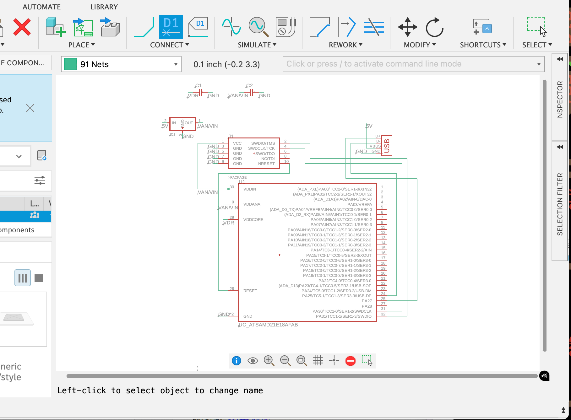
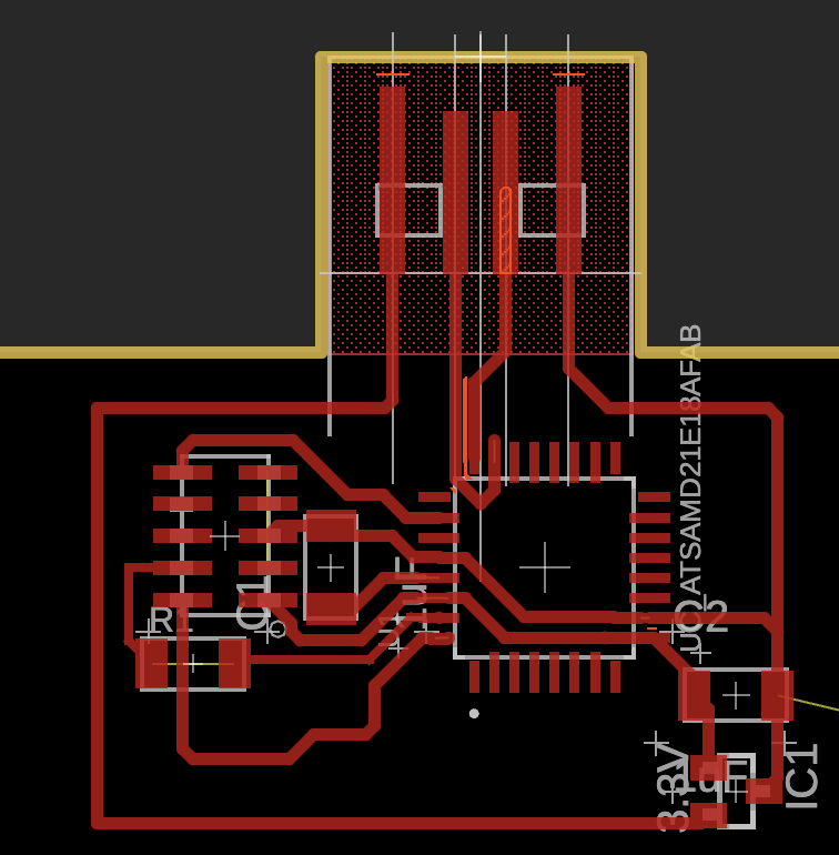
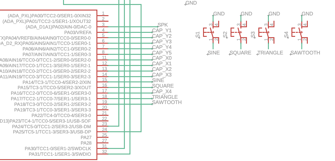
Along the way, I found inspiration from a project by Quentin, who created a PCB synth with 5 circular capacitive pads (carved using the PCB mill) and a piezo speaker. While Quentin's project used self-capacitance for input, I wanted a design that could support two octaves (24 keys) of capacitive touch, which required mutual capacitance sensing (as there are only 6 self-capacitance pins on the SAMD21E, as opposed to 60 pairs supported through mutual capacitance). Mutual capacitance may also enable proximity sensing, which I could use to time my release, instead of having to manually set ADSR parameters. My schematic shows how I used Y pins (PA4-8) and X pins (PA11-14, 17) for this purpose:
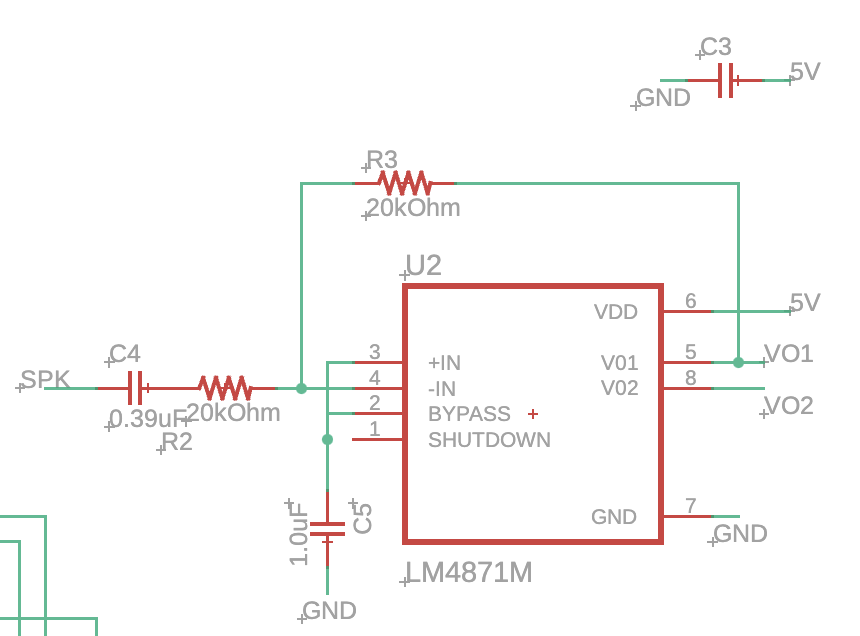
To produce audio output, I decided to pass the DAC signal through an audio amplifier before sending it to a speaker. I chose the surface-mount LM4871 amplifier and wired it up according to the typical configuration in the datasheet:
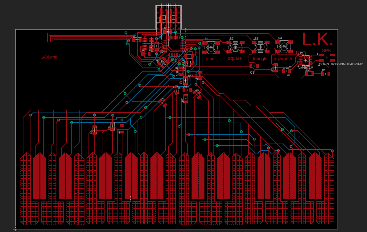
For the keyboard itself, I originally designed capacitive touch pads based on self-capacitance, but as I needed mutual capacitance, I split each key into Y and X plates with a 16 mil gap in between. The original PCB layout looked like this:

The final PCB layout includes capacitive pads for each key, switch buttons to select waveform types (sine, square, triangle, and sawtooth), and the LM4871 audio amplifier circuit. Here's the finished PCB design, ready for milling:
My next steps will be milling this design onto a PCB and writing firmware to drive audio output based on the capacitive touch inputs, using a 44.1 kHz interrupt for real-time audio synthesis. Fingers crossed for success!
Reflection
This week, I delved deep into the intricacies of PCB design and capacitive touch sensing. While there were challenges, especially with the capacitive plates, I feel like I have a much better understanding of how to approach digital synthesizers. I'm excited to see how this plays out once I mill the PCB and get the code running!
Next Week: Electronics Production →