Electronics Production
I started out this week hoping to continue from my PCB piano synthesizer project. I tried milling it on an 8x5 piece of double-sided copper using the largest PCB mill at EDS. Unfortunately, after several hours, I realized the base wasn't even, causing part of the board to not etch properly.
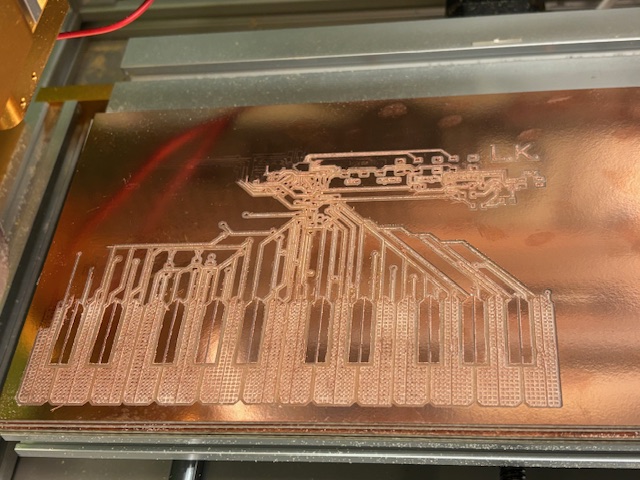
There were no other machines at EDS capable of milling a board of this size. Luckily, Anthony helped me order the design through JLCPCB, but it wouldn't arrive in time for class. So, I decided to shift my focus to other ideas: a US National Debt live tracker for the SAE party room and a custom computer mouse.
While I waited for my 64x32 pixel 5mm LED matrix displays to arrive, I made a test board with a XIAO ESP32-C3 and a dot matrix display. I followed a simple setup similar to the Week 3 setup board (reference here), and passed 5 pins through for SPI communication to the dot matrix.
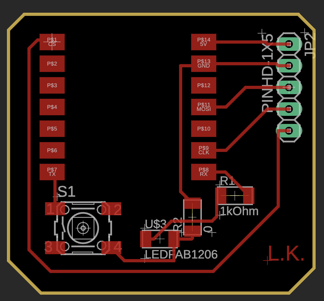
This was my first-ever PCB assembly, and it took much longer than expected. I milled the board on the Roland machine at EDS and used epoxy to maintain the throughhole connections. I also had to add jumper wires for proper connection to the display.
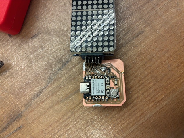
Once I flashed the code, the display powered on (although it didn’t display anything interesting).
By this time, I had already determined the API endpoint for the national debt, but I became more interested in testing the optical gaming sensor I had ordered online. I decided to hold off on the WiFi integration with the dot matrix display and shift focus to the custom mouse design.
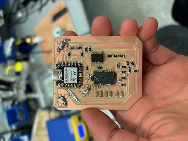
I designed and milled a new PCB for the mouse, closely following the datasheet of the optical sensor I ordered. Unfortunately, I had to sign an NDA to view the datasheet, so I can't share much about the part.
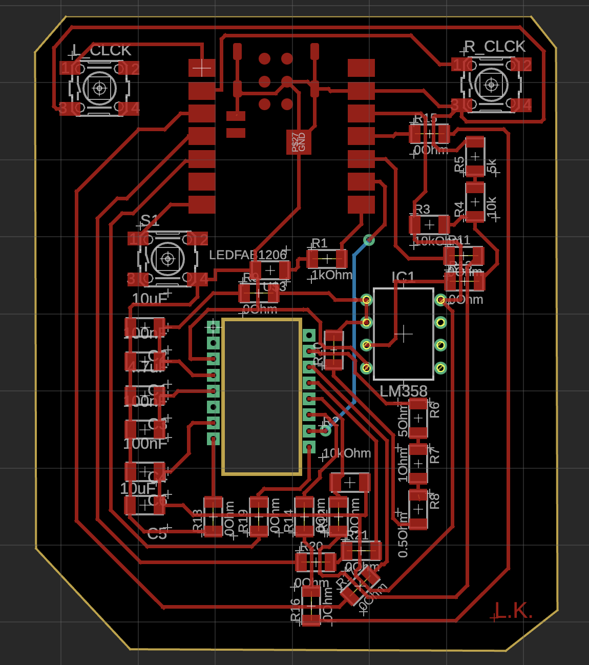
I milled the board using the Othermill machine, the last of the three PCB machines at EDS. Despite more parts being involved, I had built some muscle memory with the microscope and tweezers. Leaded solder, while controversial, made things easier for me. I also got help from Anthony and Sam with post-processing using the SonicSaber (ultrasonic knife) to fix a part that hadn’t been cut as far as needed. Some ground traces were damaged, but Alec helped me resolve this with jumper wires.
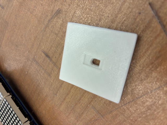
I also designed and 3D printed a baseplate for the sensor lens based on the datasheet.
When it came time to write the firmware, I figured out how to read consistent values over SPI from the sensor. The issue was integrating HID mouse functionality via Bluetooth on the ESP32-C3. The serial output showed the correct delta x and y values (in 16-bit hex), but the cursor would only move up or down even when there was horizontal movement.
There weren’t many good libraries for this task, based on my quick search. I hope to resolve the Bluetooth issues soon so that I can move forward with my shoe mouse project next week (for molding and casting).
Next Week: Molding & Casting →