
This week the CBA section made a decision making machine!
I was out sick for the first half of the project unfortunately so by the time I was able to come in, most of the main tasks had been completed or taken on by others
but I was still able to jump in and help with a few things. Aside from being around for a lot of the testing and helping with the video a bit, here were my specific contributions to the machine:
Other members of the group had cut out an acrylic base for the machine but it needed holes to secure the base and for the brackets holding the paper in place. I worked with Brian to
line up the base of the machine and make holes to secure the legs. We also carefully lined up where the paper would go (this had to be pretty precise because the operating range of the machine
barely fit the range of our decision sheets which it needed to draw on.) We also had to place the brackets precisely because they needed to fit a standard 8.5x11" piece of paper so it wouldn't
slide around when the machine was drawing.
This task was relatively simple but took a while to measure out and execute. I had the idea to cover the base in masking tape and mark out the holes on top of that. We marked out the leg holes, aligned those,
and then figured out the drawing range, aligned a decision sheet with that, drilled for one bracket and screwed it in, and then placed the remaining brackets to fit a sheet relative to the first one, marked them
all out, and drilled everything. We countersunk all of the bolts from the bottom so the machine could sit flat. We used the drill press because it allowed us to make all of the holes straight and countersink all of them
to the same height. When all of the holes were done, we assembled it all! Screwing in the clamps took some time to align as well- the holes were a bit bigger than the screws so we needed to check all of the alignment before
tightening them and it took a couple tries to get right.


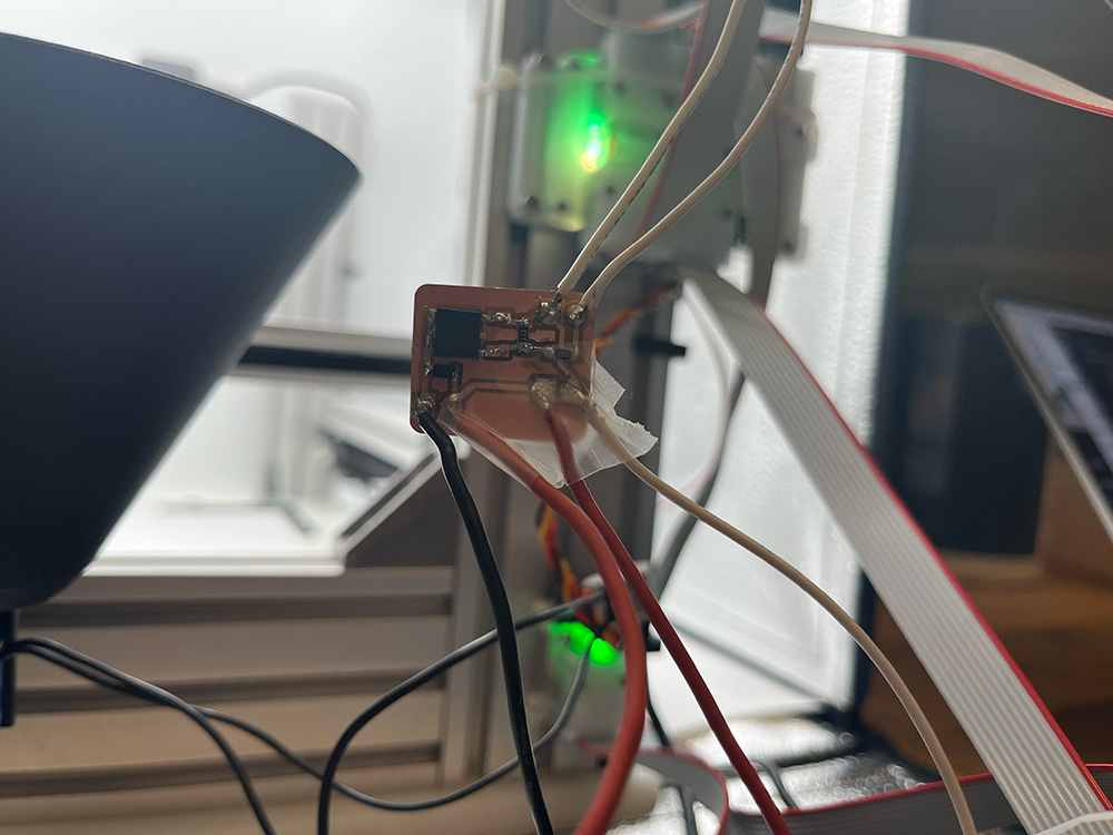
On Tuesday, we were working together to debug the machine when it wasn't running properly with our new UI. It was stressing me out how many cables were dangling everywhere as well as the solenoid PCB which was hanging on by its solder pads for dear life and some scotch tape.

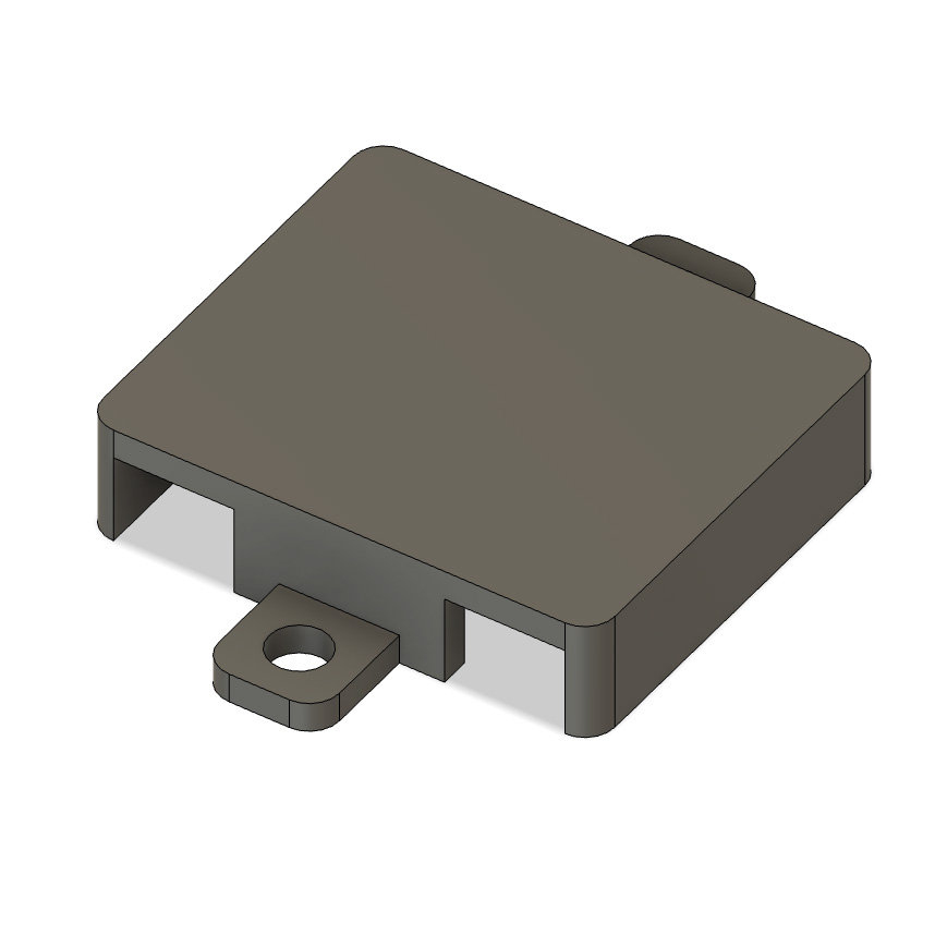
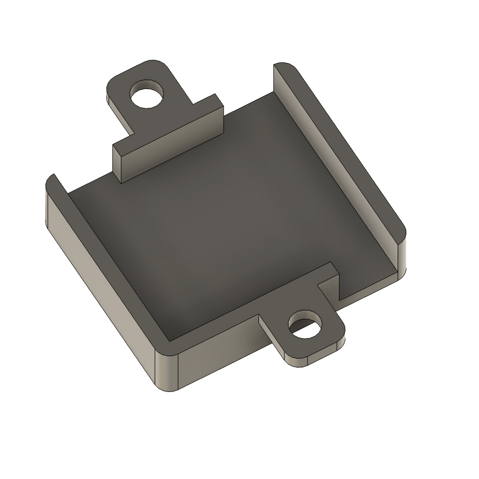
With approval from the MechE team, I got to work on coming up with a solution. First I looked at how the other electronics were mounted, and looked at where would make sense to mount the soldenoid PCB from a wire length and routing standpoint. With that figured out, I measured everything and made a design in fusion for an enclosure which would match the other ones and screw right onto the frame. I made cutouts for the wires to come out of that matched up with the layout of the PCB.


And then I printed it out and Cyrus and I installed it by hot gluing the PCB into the enclosure (to help robustify the solder points for outgoing wires) and screwing it on. This was a pretty simple thing but I am really proud of this contribution because it was
my first time going from identify part need -> design part -> 3d print part -> install part, all on the spot and without any hitches. And this was only my second time designing and making something myself with the FDM printer!
There wasn't much time left to work on the machine and integrate proper canle management, which was unfortunate but I still wanted to improve the situation because there were so many cables just hanging out. Cyrus showed me which existing parts we had that could screw into the frame
and we worked together to use those to secure some parts, and then routed and zip tied all of the cables. It wasn't proper integration but for the amount of time and materials we had at hand, we did out best, and the final product was a lot more neat and secure than we started with.
I didn't get any good before pictures because we were in a rush to get things done but you can see how neat it turned out afterwards!

