Week of Oct 2 2024
Use test equipment to observe microcontroller circuit board operations, and use an EDA tool to design a development board to interact and communicate with an embedded microcontroller
1. Use test equipment to observe microcontroller operations (group)
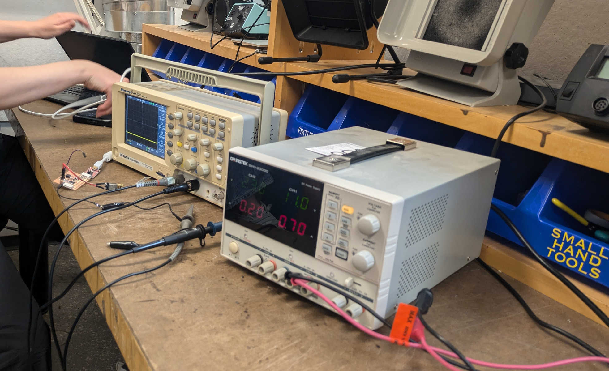
I started the week thinking that multimeters and oscilloscopes were the same thing. Thanks to a highly informative training by TA Diana (with compliments to TA Anthony, the TA who taught the TA), I now know better.
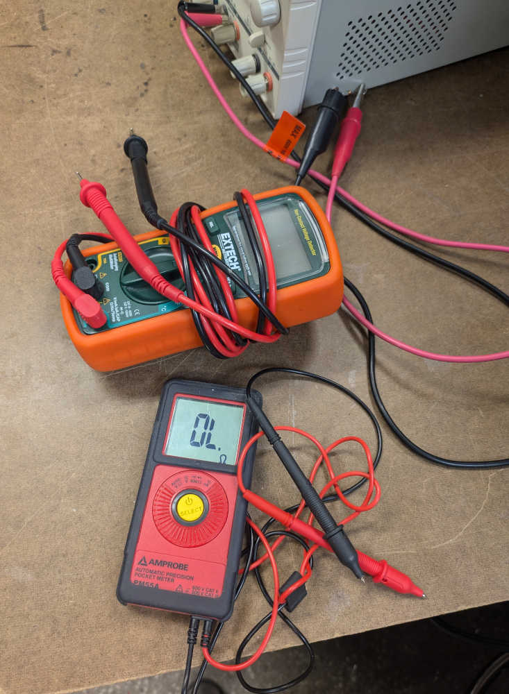
We started off with a dummy's guide to electronics using a water wheel as an analogy - the current being the volume of water, voltage being the height the water is falling from or the strength of the water flow, and resistance being the water wheel itself. As the team's eyes collectively stopped glazing over whenever Ohm's Law was mentioned, we learning how to toggle between different modes of the multimeter to measure resistance, voltage, current, and got cheap thrills out of hearing the multimeter's satisfying beeps upon detecting a closed circuit.
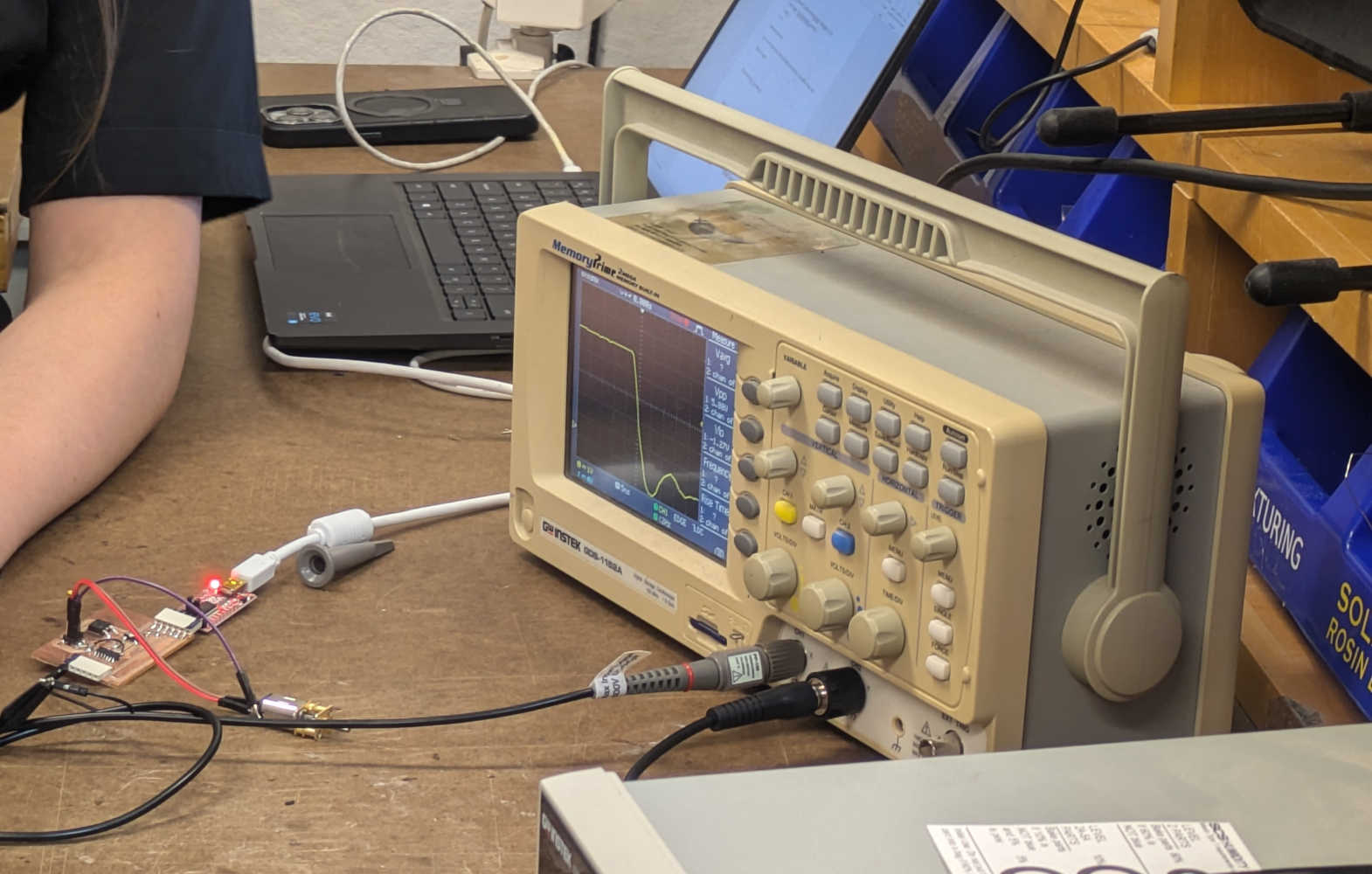
Our microcontroller and output devices of choice were a ATTiny connected to a spinning rotor, which was cool to observe in real-time in tandem with the readings on the various test equipment.
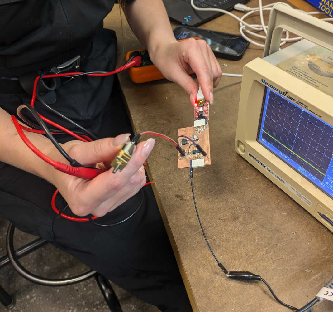
Next, TA Diana demonstrated various cool functions of the ancient oscilloscope in our shop, like how it has a 'symbol' function to capture a moment in time, and how one can stretch the y-axis and x-axis by turning dials to better observe changes in electronic signals over time. As the machine booted up to say "1975" but yet also had an SD card slot, the group debated whether it was made in 1975 and also doubled up as a time-machine (since SD cards had not been invented then). We eventually settled on the more plausible explanation of the oscilloscope's company being founded in 1975 instead.
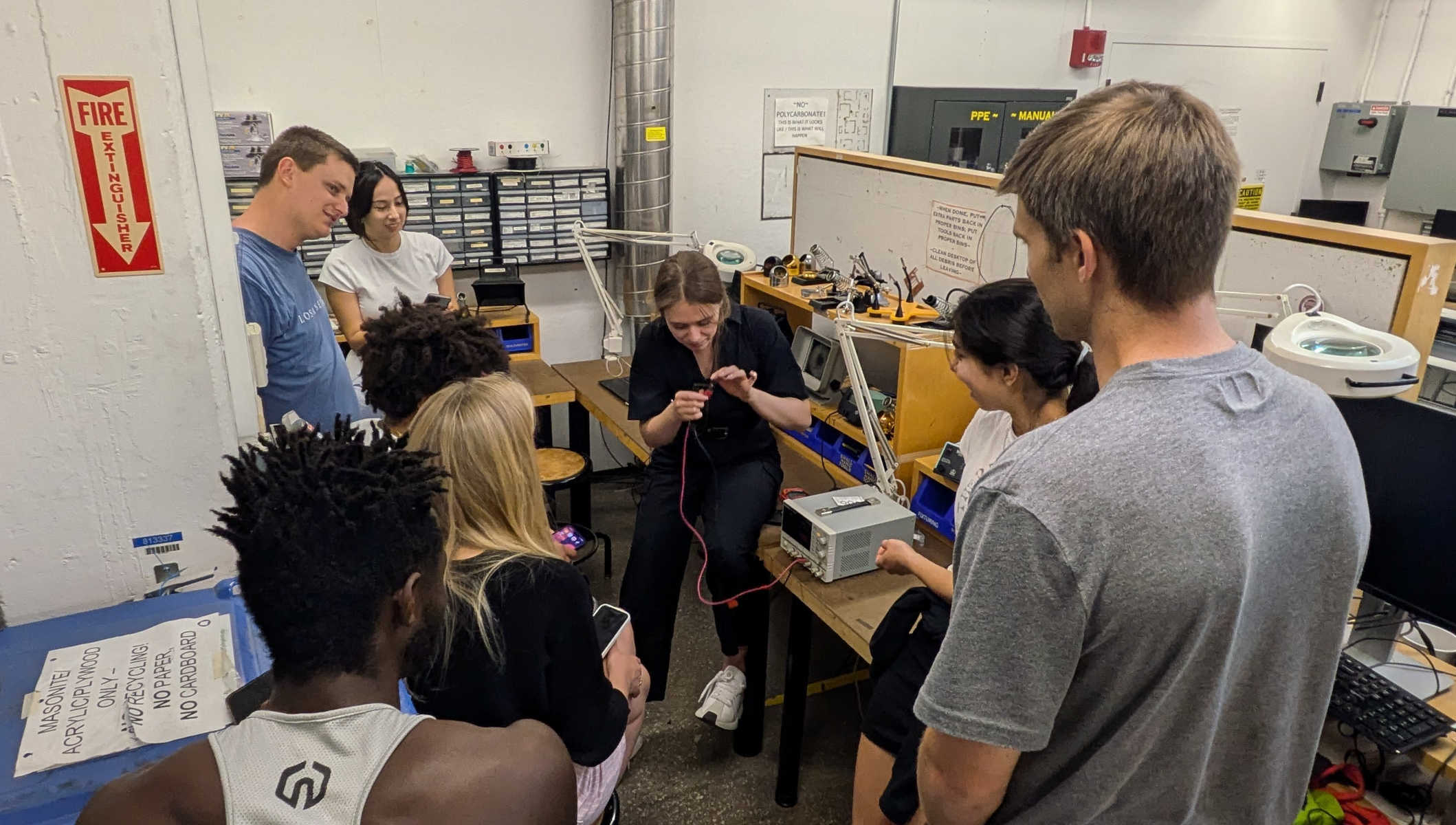
Saving the best for the last, TA Diana performed a hair-raising demonstration of connecting the power supply to a resistor and getting us to touch the resistor to feel it heating up from the power. We were taught that as long as we do not exceed 20V, we would not be in mortal danger. A good use case for the power supply would be if one's project required more than 5V (the voltage of USB ports).
2. Use an EDA tool to design a development board
I struggled with this deceptively simple-looking assignment, especially after unfounded confidence following creating a nice heart-shaped circuit board during TA Anthony's Fusion tutorial.
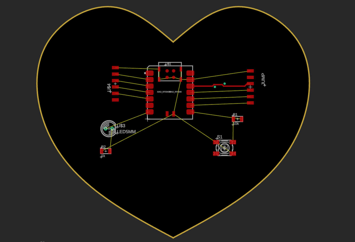
In deciding what software to use, I initially wanted to try out the custom tools developed in-house by TA Leo because they seemed to require the least prior technical knowledge; the seamless interaction between the frontend GUI of board design and backend code also seemed like a great way for me to further improve my understanding of various coding languages. But alas, TA Leo did not have office hours available this week, and from the past weeks' experience, TA instruction availability has become pretty high on my priority list when making decisions for this class. The other two main options I considered were the open-source KiCAD, and Eagle embedded within Autodesk Fusion. As I wanted to eventually pick up Fusion, I elected to try working in Eagle given its integration within Fusion. I would still love to try out KiCAD at some point this semester though - am a big fan of open-soure software.
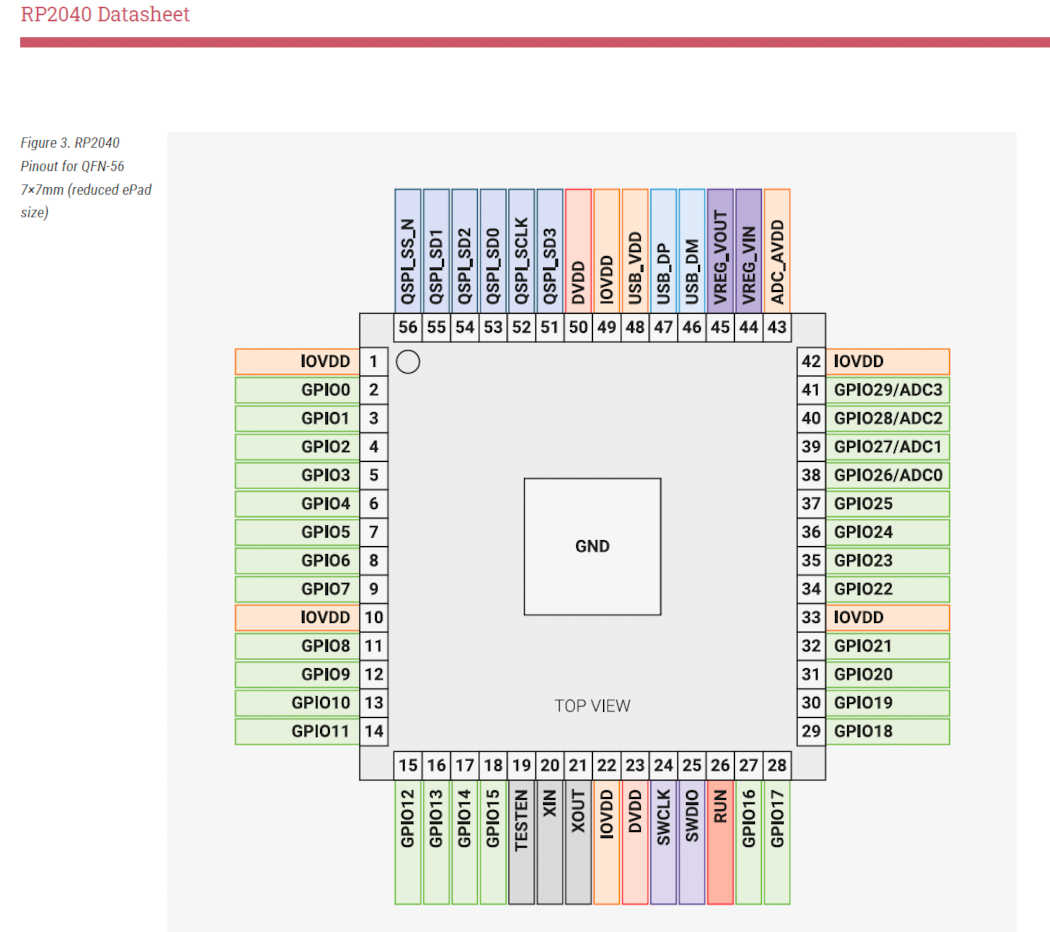
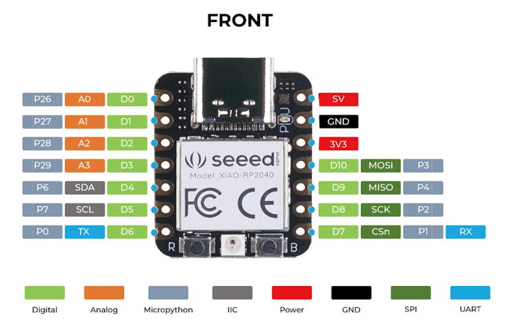
I started off eagerly and diligently downloading the datasheet for the RP2040, which was what I wanted to eventually use for my final project. However, I quickly got confused at how the pin-outs did not match the RP2040 component in Fusion Eagle at all, and I did not know where to start finding out what components I needed to place on the EDA. No amount of ChatGPT consultation resolved my query, so I went to CBA office hours, where TA Alfonso kindly guided me towards the right direction. Takeaway #1: Focus on getting the basics right. I had been looking at the chip (RP2040)'s pinout, instead of the microcontroller (SEEED XIAO board with RP2040) that was the component I pulled in on Fusion. TA Alfonso also explained how the Raspberry Pi microcontroller was developed specifically for the RP2040 and so the pinouts match that of the chip itself, whereas the XIAO board is a simplification. Lightbulb moment!
The 2nd salient takeaway from office hours was that going through past HTMAA/ Fab Lab projects is a great way to get unstuck - so I used the search function within the class site to retrieve multiple past student projects that utilized an IMU, which is the current input sensor I have in mind for my final project. Seeing images of the actual components I would use later was immensely helpful as I could now visualize the end product instead of sketching in a 2D vacuum.
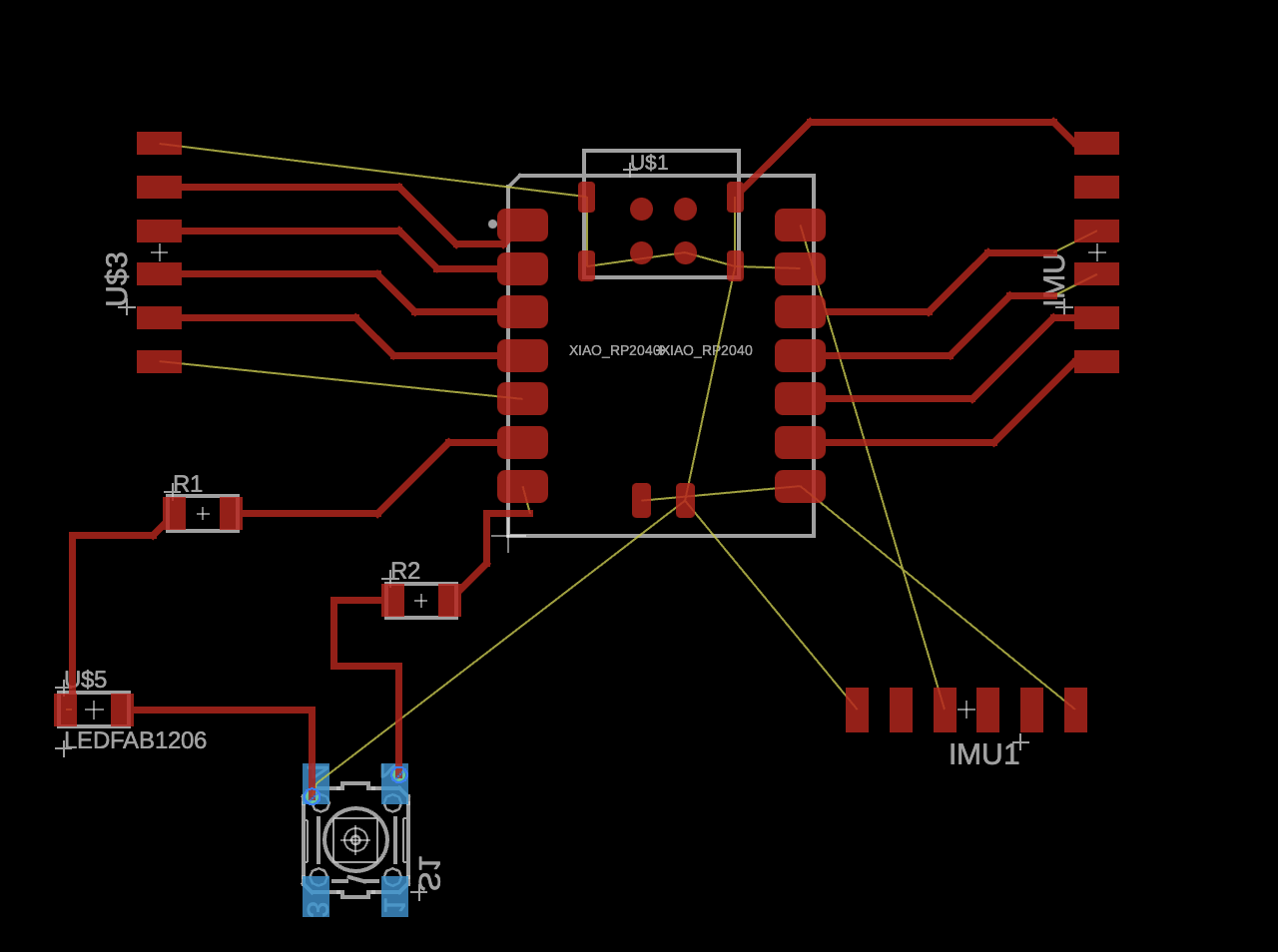
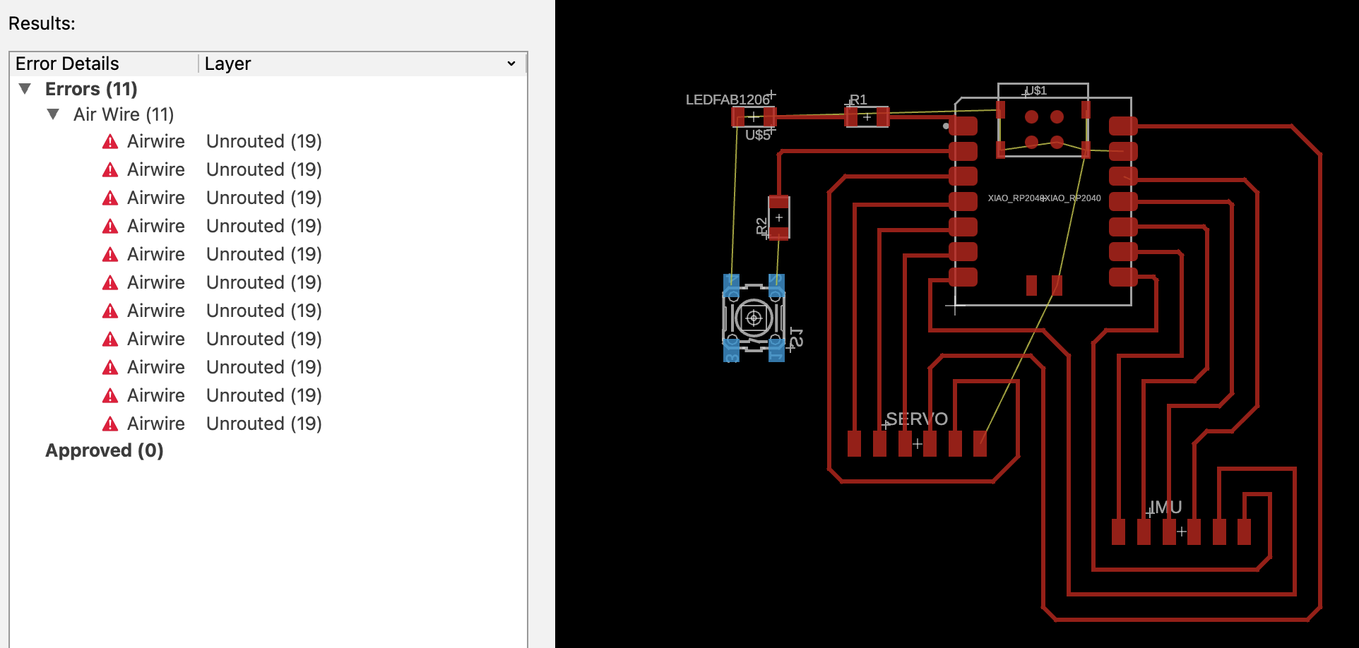
I knew I wanted to connect an IMU as an input and a servo motor as an output. Since the XIAO RP2040 board already came with a USB port, as well as an in-chip convertor that could regulate the 5V from USB ports to the 3.3V maximum of the XIAO board pins, I did not need to add in a voltage regulator either. Initially I wanted to have 3 6-pin connectors, 1 for the servo, 1 for the IMU, and 1 extra, as well as to throw in a switch, an LED, and 2 resistors. However, I misunderstood how routing worked and ended up with way too many unconnected pins - see picture above for airwire error galore.
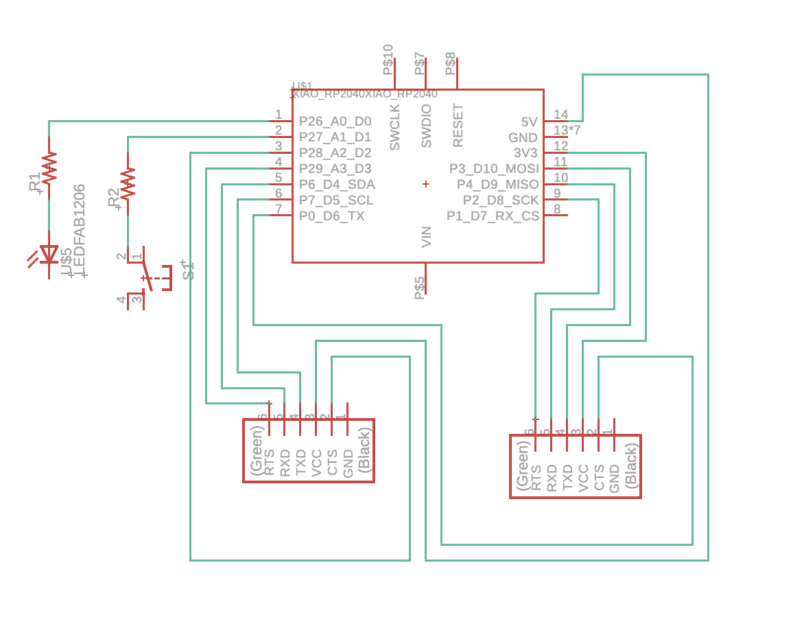
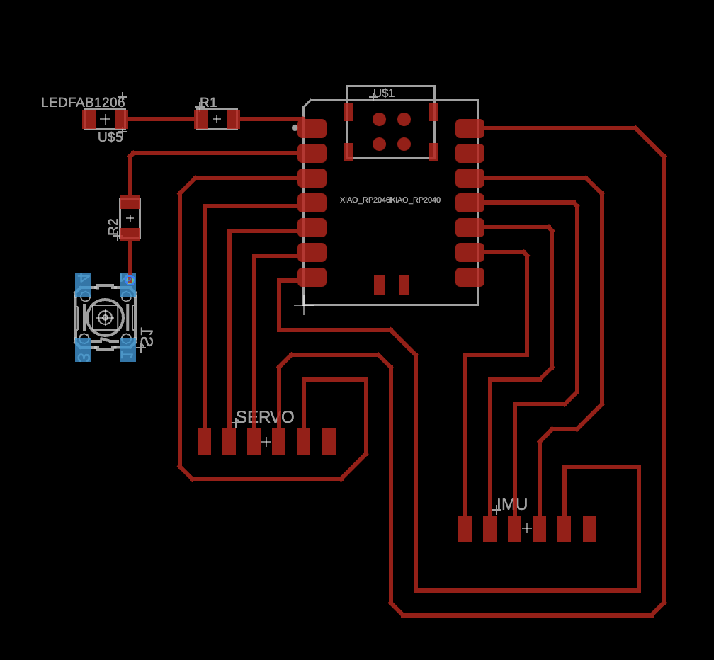
I realised that removing all the ground connections resulted in the removal of errors. I was about to export the image and call it a day, thinking that all the ground pins could be soldered to a single ground plane, perhaps on a 2nd layer. But my spidey sense told me that this could not be it, and I decided to dig around for answers. The great thing about using Fusion for this semester's course is that TA Anthony had very helpfully added us all to a Fusion cloud folder, where we had access to some example files he prepared on various microcontrollers - both good and bad examples of schematics. It was through reviewing these examples that I realised I squarely fell into the "bad schematic" example of unncessarily connecting all the pins, when I could have just "named" it by pin name, and spent time more wisely finessing the connections in the schematic view instead. I also got confirmation from those precedent Fusion Eagle files that I had to connect the ground pins. Back to the drawing board!
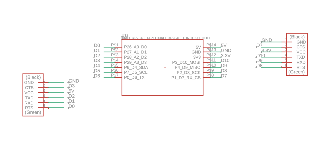
I wanted to split the 2 power sources on the XIAO board to 2 different connectors, so that the servo motor can be plugged into the 5V source, and the IMU into the 3.3V source. Trying to fit in the switch and LED while balancing the routing of such a PCB became impossible, so I simplified my PCB to just having the XIAO and 2 connectors. For production, I intend to solder another 2 connectors to where the XIAO board sits, so that the XIAO RP2040 microcontroller could be unplugged easily and reused.

There were still design rule errors, which I attributed to the Fusion component setting where the USB port of the XIAO board was not "masked" and as such triggered unconnected airwire errors. I solved this by replacing the component with a "taped" version of the XIAO board in the 'fab' libary instead.
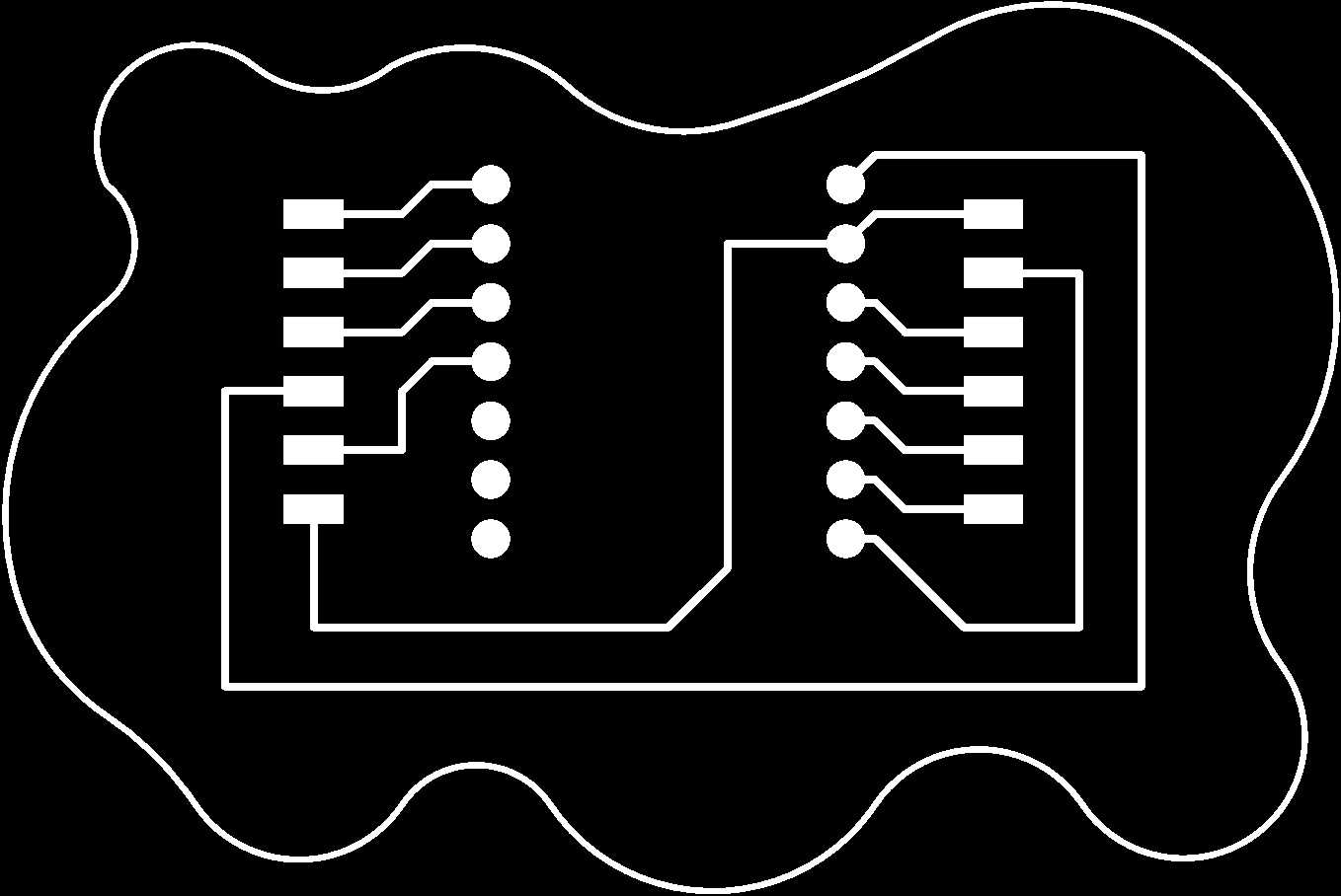
And just like this, my very first (hopefully functional) PCB board layout is done, ready for the next step of production.
Design file link to the Fusion Eagle schematic document for my PCB.