Week of Oct 30 2024
Add an output device to a self-designed microcontroller board and program it
This week I am getting the hang of the workflow for approaching the unknown (i.e. electronics), with the help of the following trusted processes:
- Go to the class inventory to see what hardware is available to play with; this week's inventory here. (In general click on the title of each week to get to the week-specific inventory; otherwise overall class inventory for 2024 here
- Check out workshops in person to see what components and connectors are available. Breadboard + jumper wires/ soldering jumper wires onto PCBs are handy for quick testing, in between PCB redesign and milling (e.g. if waiting for the mill to be free) or if particular connectors are out of stock.
- Download datasheets for components I am interested in, to check out the pinout.
- Update schematic electronics design in Fusion Eagle with how the components connect to each other, i.e. what pin connects to what
- Compile questions for TAs, reach out for help (email/ git issue tracker/ go to office hours in person). TA consultations are singlehandedly the MVP of this class! All hail our star TAs! You can't spell HTMAA without TA after all.
- Use example code in Arduino IDE libraries and good o' ChatGPT to troubleshoot and refine my code.
To start, here are the specs of all components I used this week, for ease of reference:
Microcontroller: SEEED XIAO RP2040

Source: SEEED Studio
Source: Tinygo
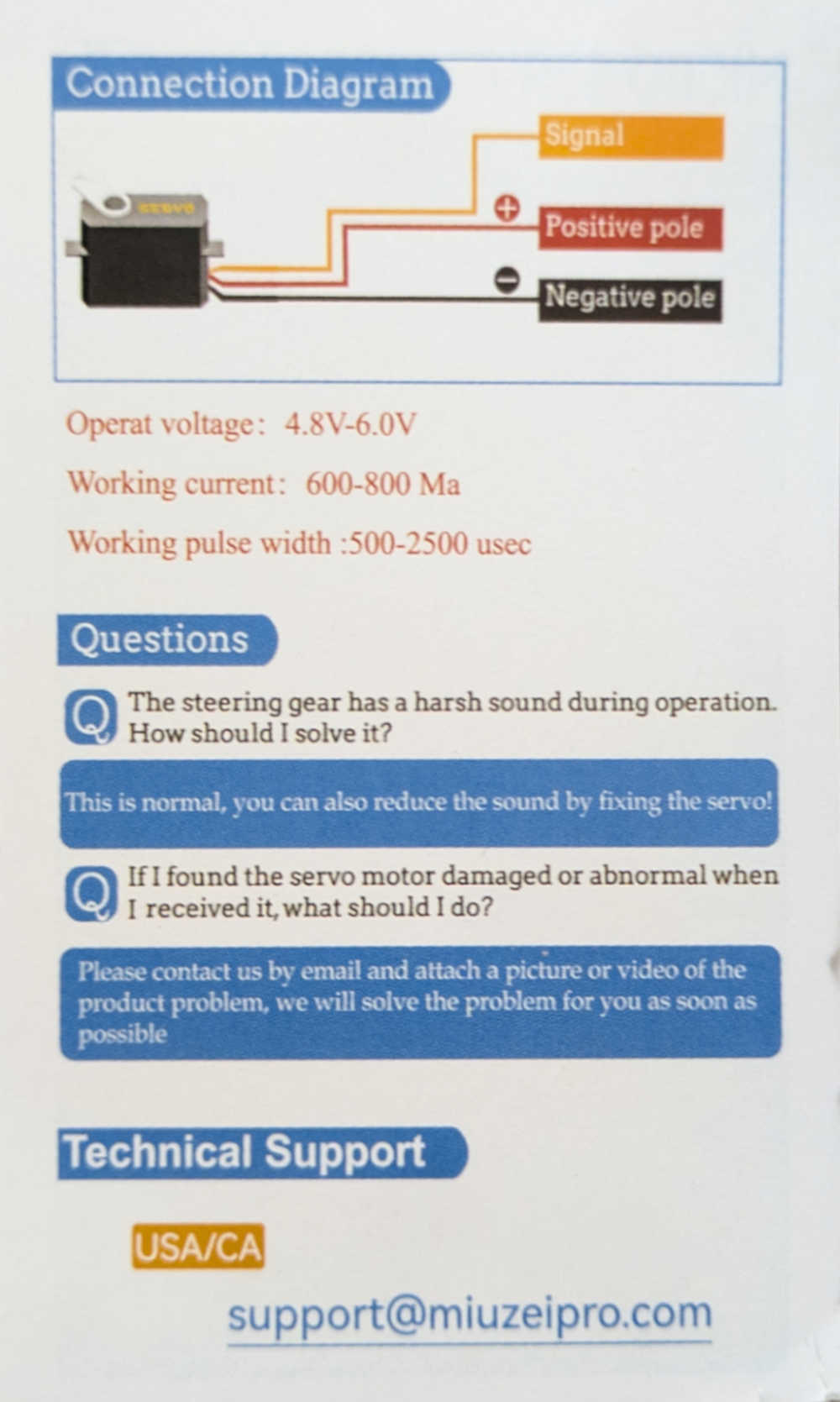
Output device: Miuzei Servo Motors (considered the MG90S and MG996R models)

Source: Miuzei Shop on Amazon
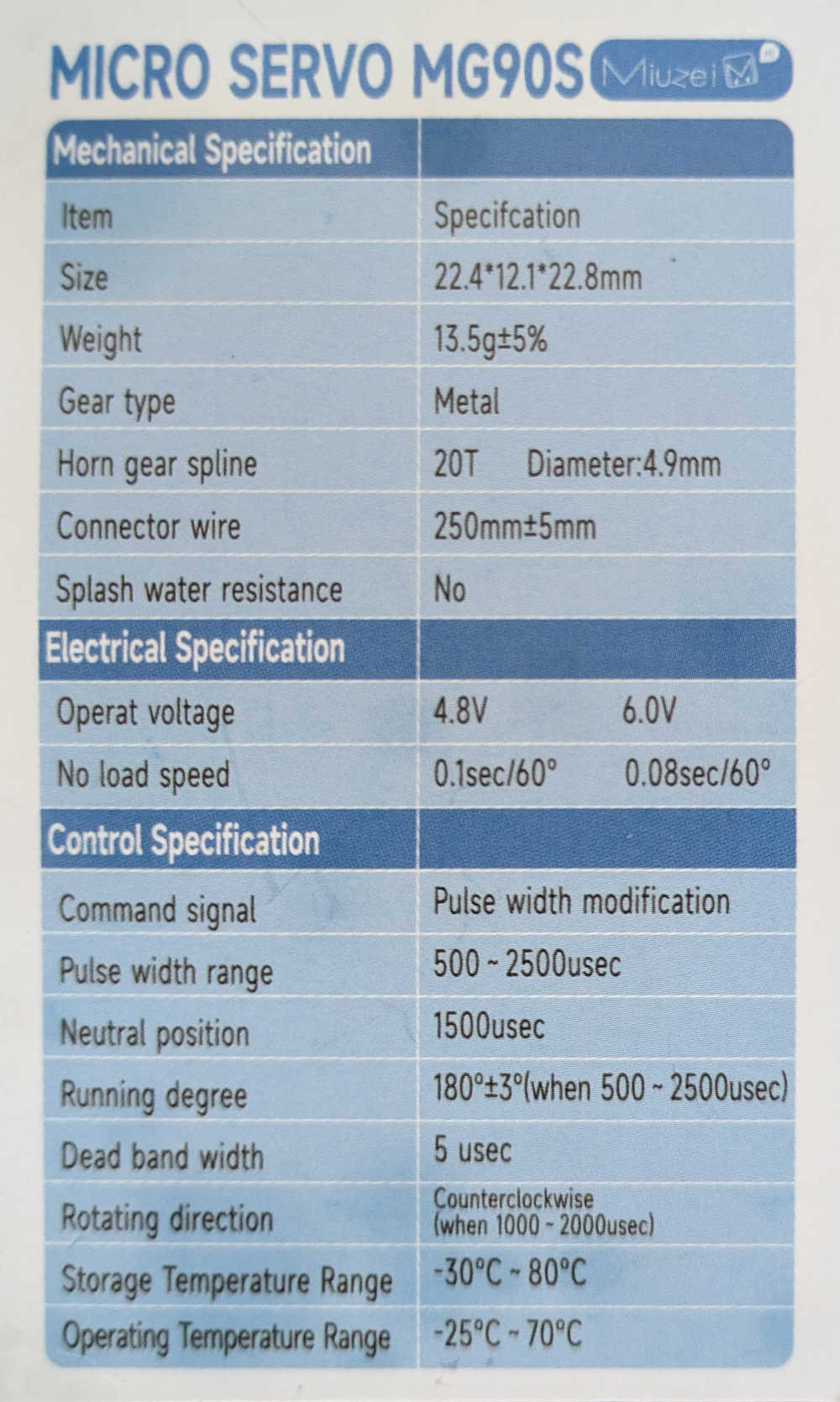
Source: Miuzei (info sheet that came with the product)
Input device: Adafruit BNO085 9DOF IMU

Source: Adafruit
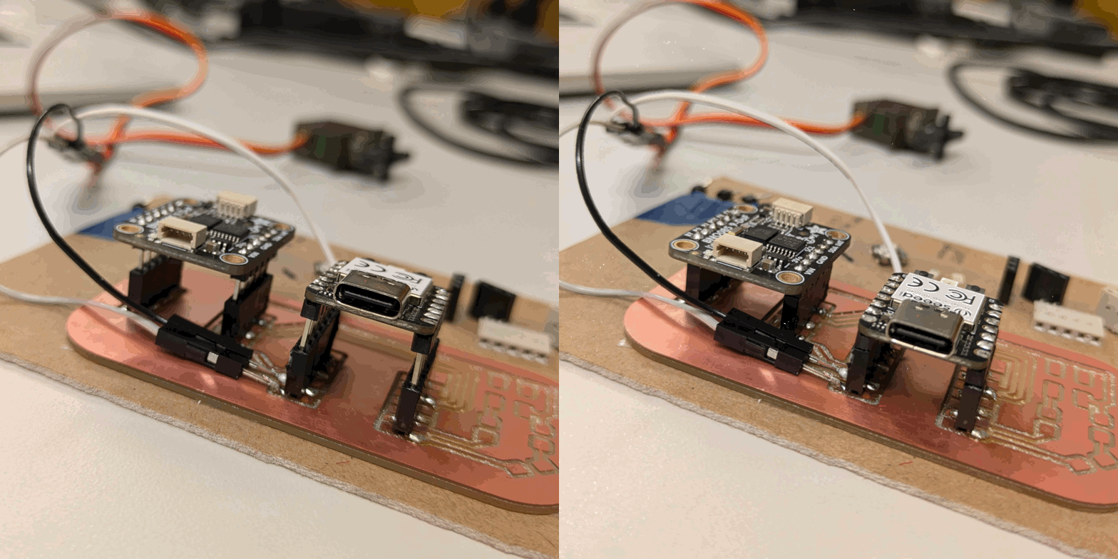
I also tackled the IMU issue from last week, where it turns out that (1) flux was not the issue since it is not conductive (2) IMU pins are meant to be directly soldered onto header pins. TA Anthony demonstrated how to perfectly solder the IMU pins in an impossibly short time. His specific technique was to heat up both the component through-hole and connector pin with the solder iron, then to push the solder wire onto the iron to continuously 'feed' solder into the throughholes. Considering that I had struggled immensely and spent ages soldering before, I was surprised when I managed to solder everything relatively quickly and smoothly. I noticed 3 key differences in the EECS workshop soldering setup which might explain why the soldering went more smoothly: (1) Much thinner solder wire (2) hotter solder iron (850 deg F).

Indeed after soldering the components, the connections worked beautifully and my IMU could be read by my laptop's Arduino IDE again!

Connecting components to the PCB: I considered milling throughholes for my next PCB for a more secure fit (i.e. components can sit lower on the PCB), but TAs Anthony and Quentin also confirmed that the current set-up was optimal, especially for plug-and-play. The throughhole set up would entail soldering the header pins (that were soldered to the components) directly on the throughholes of the PCB, which could get tricky with plastic part of the headers.

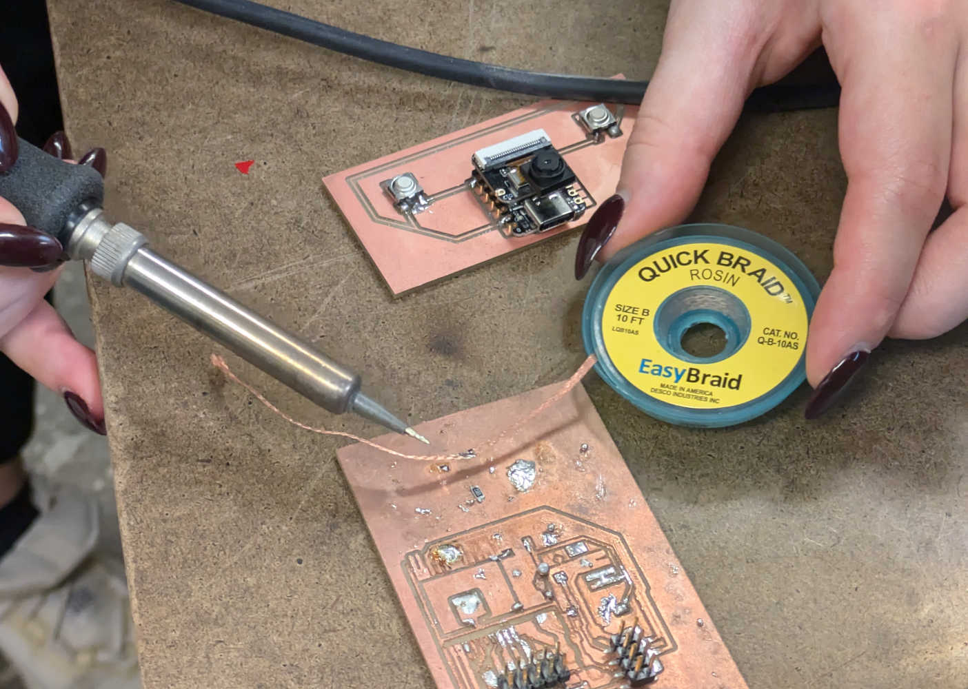
I also learnt how to more efficiently "mop" up excess solder and flux - to use copper solder braid, which acts as a paper towel for solder and flux. Another trick for treating cold solder joints was to add flux before reheating.
Now that my IMU was working, I could move on to this week's assignment proper, which is to connect my selected output device - a small Miuzei servo. I had no idea where to start in terms of programming the servo, so TA Anthony gave me an impromptu Electronics 101 masterclass on servo motors.
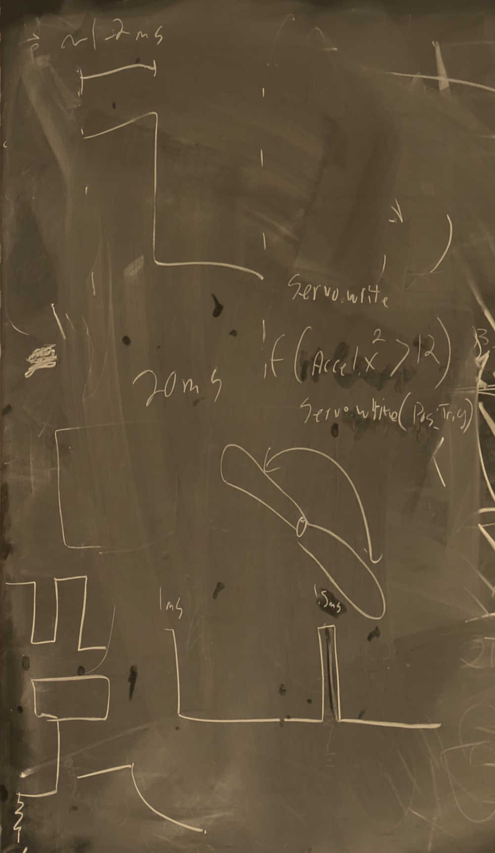
With that, I went to ask ChatGPT how to write programs to (1) check if my servo was connected (2) make the servo move. After reading through the datasheets and documentation for my components, I learnt that a servo motor typically has 3 pins - VCC, GND, Signal. The VCC should be connected to the 5V (not the 3.3V) pin of the SEEED XIAO RP2040, GND to ground/GND, and Signal to any PWM-compatible (PWM = Pulse Width Modulation) pin (refer to chart above for which SEEED XIAO RP2040 pins are PWM-compatible). I attempted to connect with my hands while trying to upload a sample code while waiting for TA Anthony to finish helping ten thousand other students relying on his expertise.
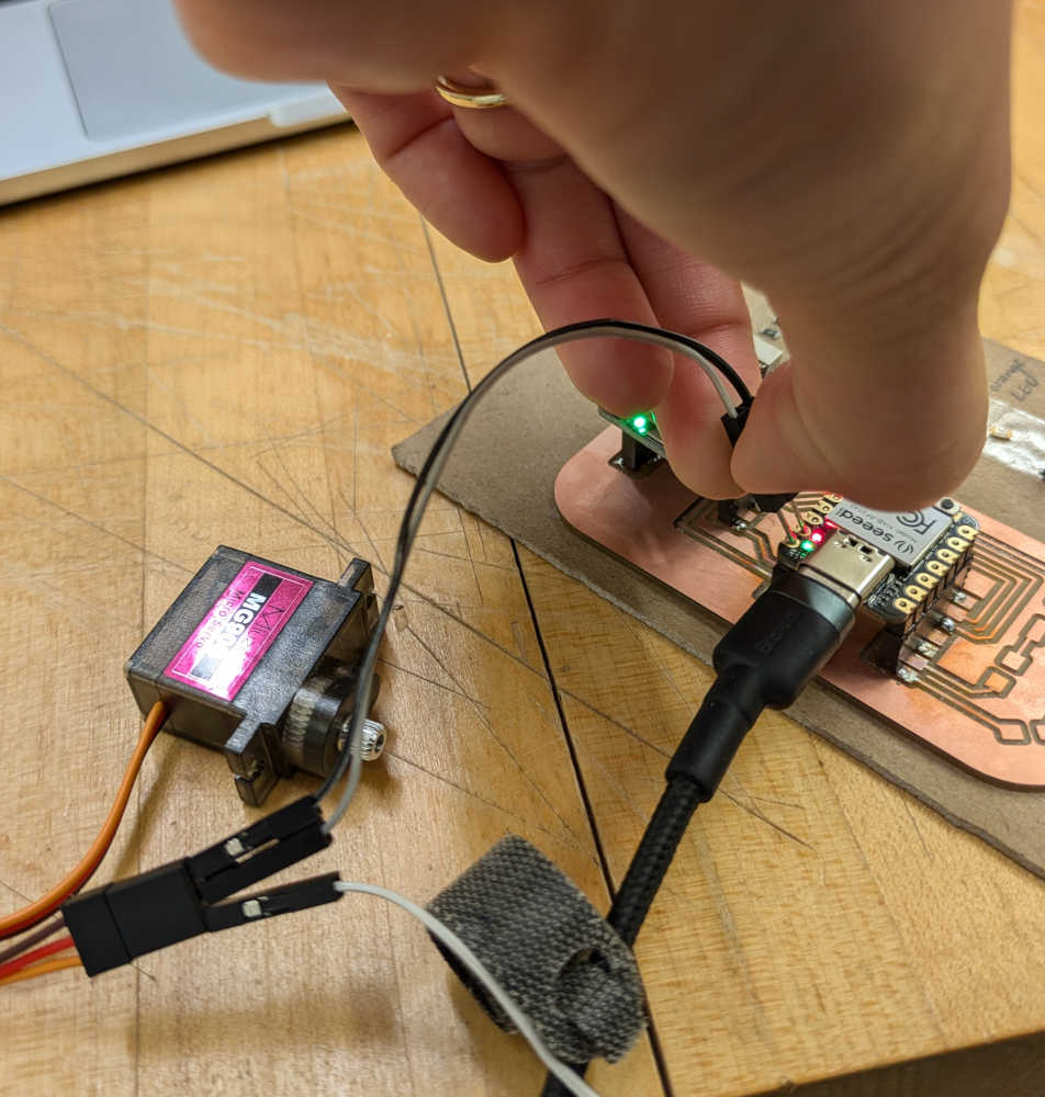
Of course it didn't work; AI has not yet taken over all human functions. TA Anthony helped me to troubleshoot the following:
- A quick way to connect components to an existing PCB sans connectors is to solder jumper wires to the largest point of the desired connection i.e. solder pads instead of along a trace.

This was my ideal connection, but will save this for a later iteration of a 3rd PCB designed with this 3-pin connection in mind. - Change pin number to the number associated with 'micropython' (see SEEED XIAO RP 2040 pinout above) and not the one associated with 'digital'; alternatively specifying pin as "D7" instead of "7" could work too.
- There is only one-way communication from the microcontroller to the servo, so running a program to check whether a servo is attached won't work; the only way is to directly tell the servo to move.
And lo and behold, got the servo to move! This was using the chonkier Miuzei servo (MG996R model), compared to the smaller Miuzei MG90S. Discussed with TA Anthony that depending on the design of my final project (releasing a convertible helmet held in compression), I could either use a small servo if there are secondary compressive forces (e.g. tensile tent-pole-like sticks), or use the larger servo to brute force the release.
Next up, to get the servo to respond to the IMU. TA Anthony suggested taking one of the readings of the IMU (e.g. acceleration), defining a threshold, and assigning a servo action to it. I bashed through multiple iterations of such a code with ChatGPT, entering the error prompt from Arduino IDE back into ChatGPT each time, until the code worked. Thereafter, I adjusted the 'threshold' until I was satisfied with the sensitivity of the servo's response to my IMU movement - not too sensitive (i.e. servo moves even when IMU was not moving), and not too unresponsive (i.e. servo moves inconsistently when I shake the IMU, probably due to some of the shakes not being strong enough). Full code below.
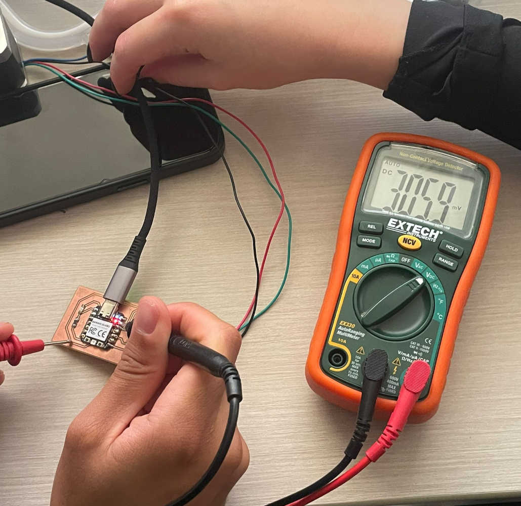
For the group assignment, we measured the power consumption of an output device - a motor (unfortunately hidden by the hand in the picture below). TA Diana taught us to measure voltage in parallel, and current in series.
Code for triggering a servo with an IMU, that was uploaded to a SEEED XIAO RP2040 via Arduino IDE:
#include <Wire.h>
#include <Adafruit_BNO08x.h>
#include <Servo.h>

Adafruit_BNO08x bno = Adafruit_BNO08x();
Servo myServo;

// Acceleration threshold to trigger the servo movement
const float accelerationThreshold = 10.0;  // Increased threshold for significant movement

// Smoothing factor for acceleration (set between 0 and 1, closer to 1 for more smoothing)
const float smoothingFactor = 0.2;

// Variables to store the smoothed acceleration values
float smoothedAccelMagnitude = 0;

void setup() {
  Serial.begin(115200);

  // Initialize the BNO085 sensor
  if (!bno.begin_I2C()) {
    Serial.println("Failed to initialize BNO085!");
    while (1);
  }

  // Set up accelerometer reports
  if (!bno.enableReport(SH2_ACCELEROMETER)) {
    Serial.println("Could not enable accelerometer!");
    while (1);
  }

  // Attach the servo to digital pin 7
  myServo.attach(1);

  Serial.println("Setup complete.");
}

void loop() {
  // Fetch the latest accelerometer data
  sh2_SensorValue_t sensorValue;
  if (!bno.getSensorEvent(&sensorValue)) {
    Serial.println("Failed to read acceleration data!");
    return;
  }

  // Extract acceleration data
  float accelX = sensorValue.un.accelerometer.x;
  float accelY = sensorValue.un.accelerometer.y;
  float accelZ = sensorValue.un.accelerometer.z;

  // Calculate the total acceleration magnitude
  float accelMagnitude = sqrt(accelX * accelX + accelY * accelY + accelZ * accelZ);

  // Smooth out the acceleration magnitude
  smoothedAccelMagnitude = (smoothingFactor * accelMagnitude) + ((1 - smoothingFactor) * smoothedAccelMagnitude);

  Serial.print("Smoothed Acceleration Magnitude: ");
  Serial.println(smoothedAccelMagnitude);

  // Trigger the servo only when the smoothed acceleration magnitude exceeds the threshold
  if (smoothedAccelMagnitude > accelerationThreshold) {
    Serial.println("Sudden movement detected! Triggering servo.");

    // Trigger the servo to move to a new position
    myServo.write(90);  // Move to 90 degrees (adjust as needed)
    delay(500);         // Hold the position for half a second

    myServo.write(0);   // Move back to 0 degrees

    // Reset smoothed value after action to avoid repeated triggers
    smoothedAccelMagnitude = 0;
  }

  delay(100);  // Small delay for stability
}