Week of Nov 20, 2024
Design, build, and connect wired/ wireless nodes with network/bus addresses and local input/ output devices
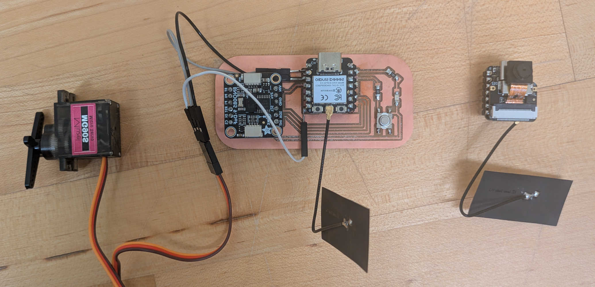
Started this week trying to build upon the electronics components I had been working on thus far (SEEED XIAO RP2040 microcontroller + servo motor + IMU), with the intent to be able to remotely control the set-up with another microcontroller, and/or to have another IMU as a control (i.e. one IMU on the ground of a plane, one IMU to actually sense movement to trigger servo movement, to cater to calibration difficulties on a parabolic flight).
After consulting the ever helpful and knowledgeable TA Anthony, I realized that I could only have wired connections between several XIAO RP2040s, but for wireless connections, I would need to use microcontrollers like the XIAO ESP32 Sense that have wifi capabilities. Since I was not so familiar with how and where to start this week's assignment, I followed TA Anthony's advice to start with something simple - following along a tutorial to try to get the wifi camera of the ESP32 Sense to work.
I referenced the traces that Neil showed in this week's lecture to mill a new PCB, but alas, ran into 2 issues.
The first issue was accidentally using a 1/32 endmill (meant for outlines) for my traces - all because a previous user placed a 1/32 endmill in a case labelled for a 1/64 endmill (the correct one to use for trace milling). Lesson learnt to always double check the actual width of the endmill and not rely on labels!
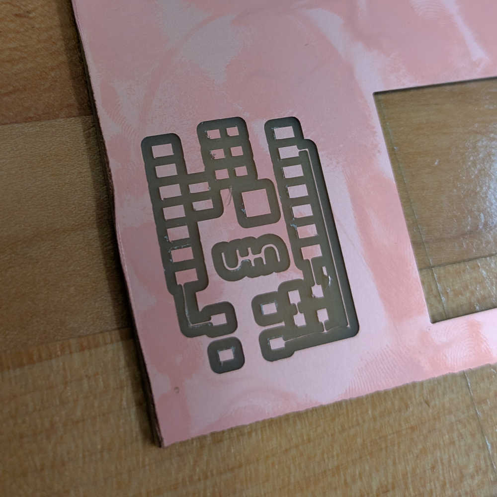
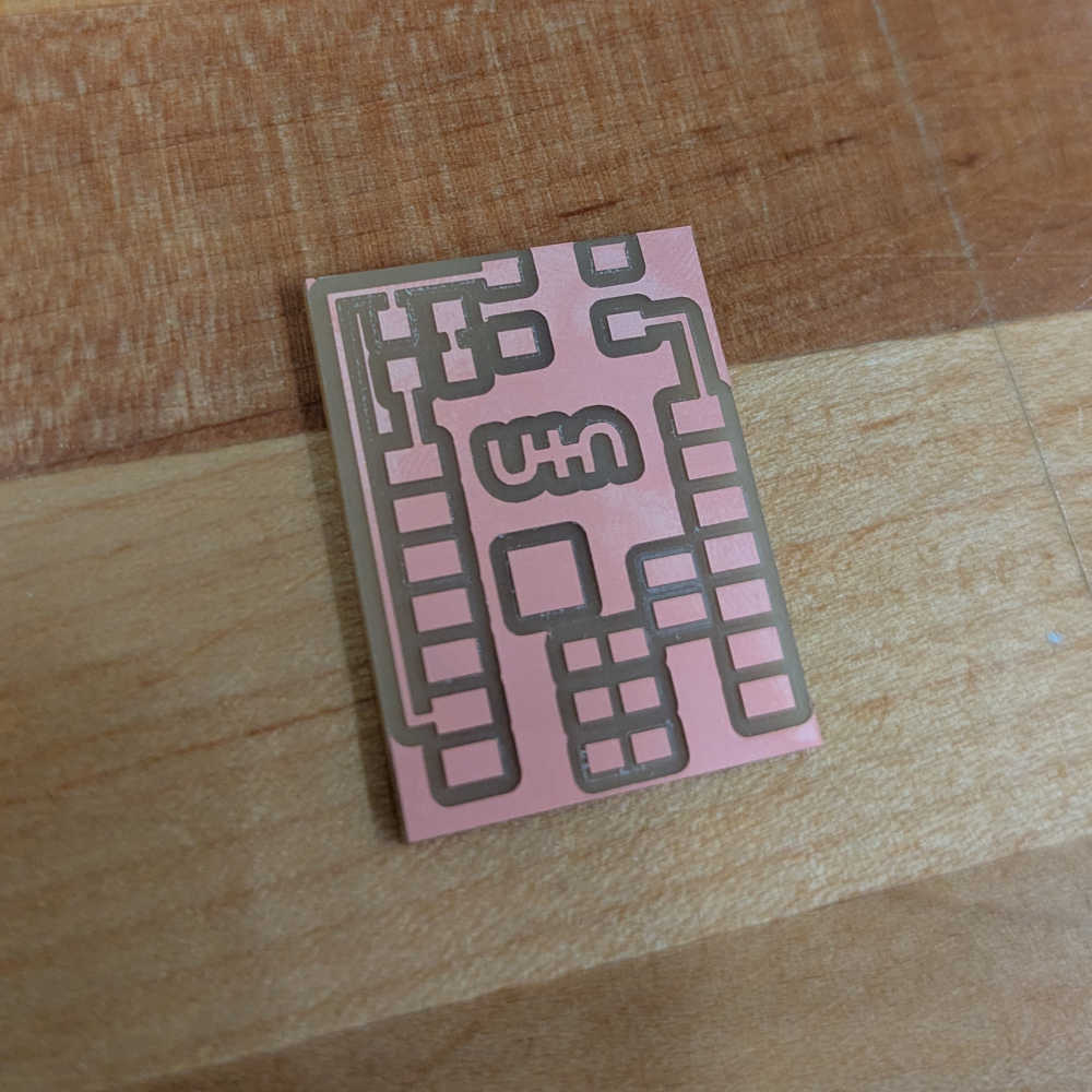
After milling the PCB correctly, quickly realized upon comparing with the data sheets of the components that I wanted to use (a tactile switch), that the PCB design did not match the pinout of the component. Thus, I could not use this PCB to install the components that I wanted to (tactile switch, LED light, and resistors).
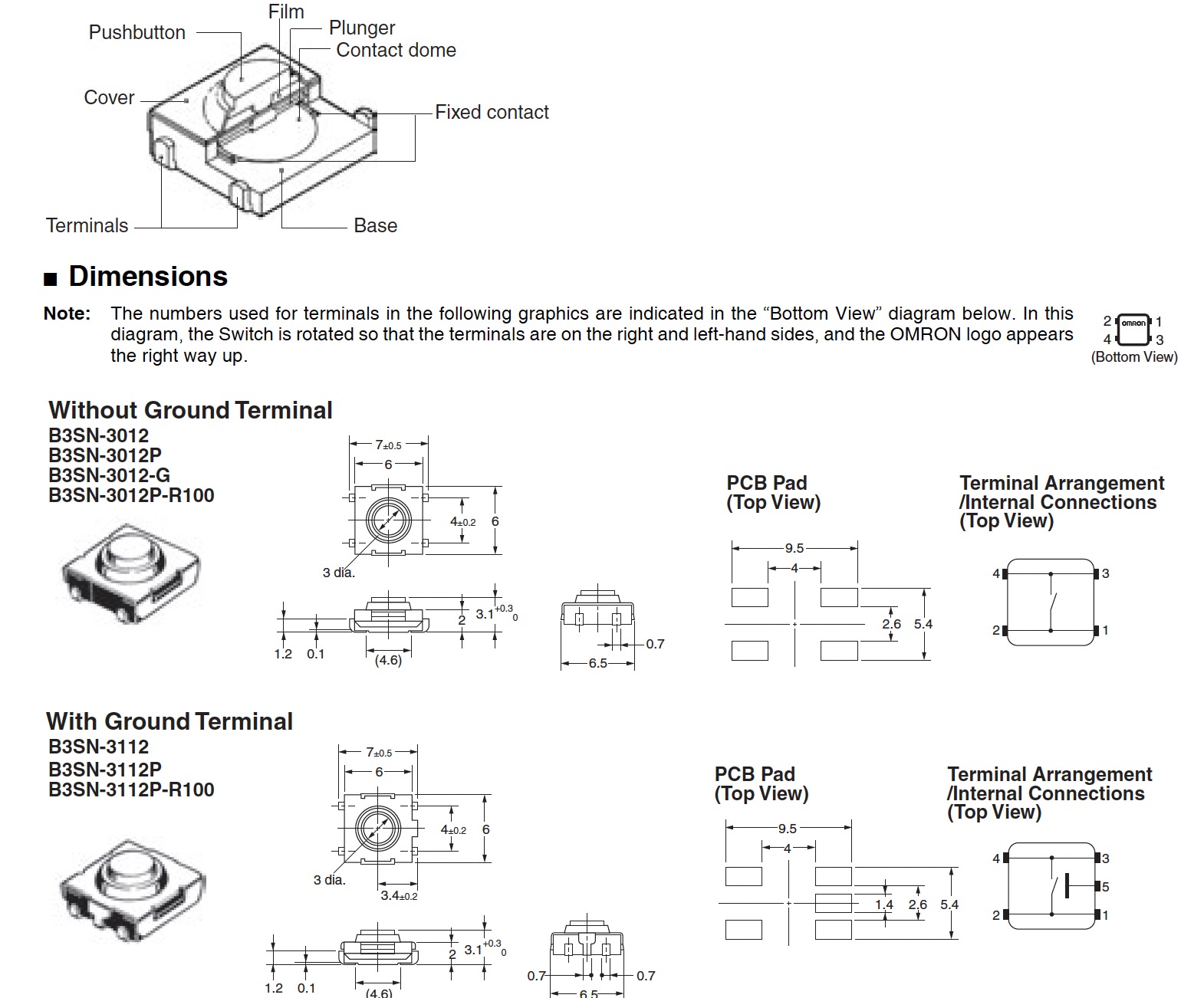

At this point I should mention that I wanted to take this week as an opportunity to revisit outstanding electronics component improvements from earlier weeks, namely fixing the resistance from 10k ohm to 1k ohm so that a connected LED light could be brighter. I also wanted to try uploading and modifying various LED blink and tactile switch codes onto my board. Soldering this week was much less painful than my first attempts, after having been guided by TA Anthony on soldering techniques, something just clicked! And things take a much shorter time. The joy of overcoming steep learning curves!
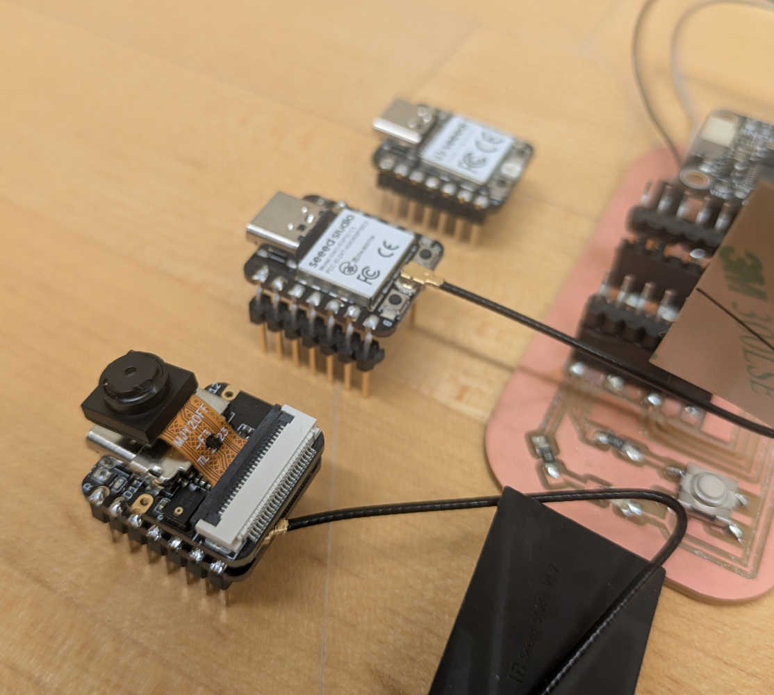
Thankfully microcontrollers in the SEEED XIAO family have matching pinouts, and I was able to replace the XIAO RP2040 with a XIAO ESP32 Sense on my existing PCB. Did some troubleshooting with hardware connection, namely attaching the various components on it (camera and antennae attachment - the trick is not to directly push it in but to clip on from an angle and nudge the opposite side in from the side).
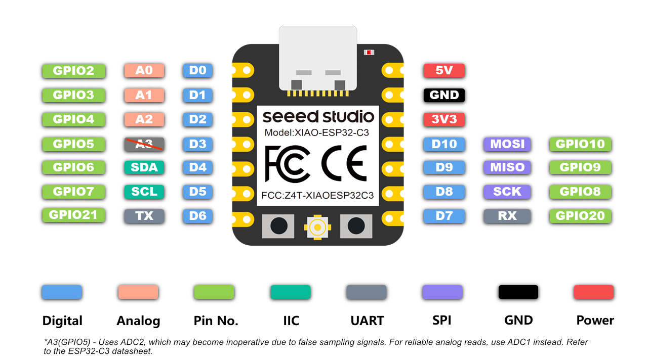
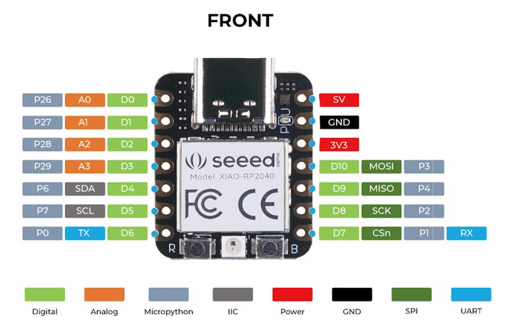
I followed along this tutorial to set up video streaming. I had to change a lot of settings in the Arduino IDE, and trial and error with toggling settings on and off/ adjusting settings. I kept getting these 2 errors in particular:


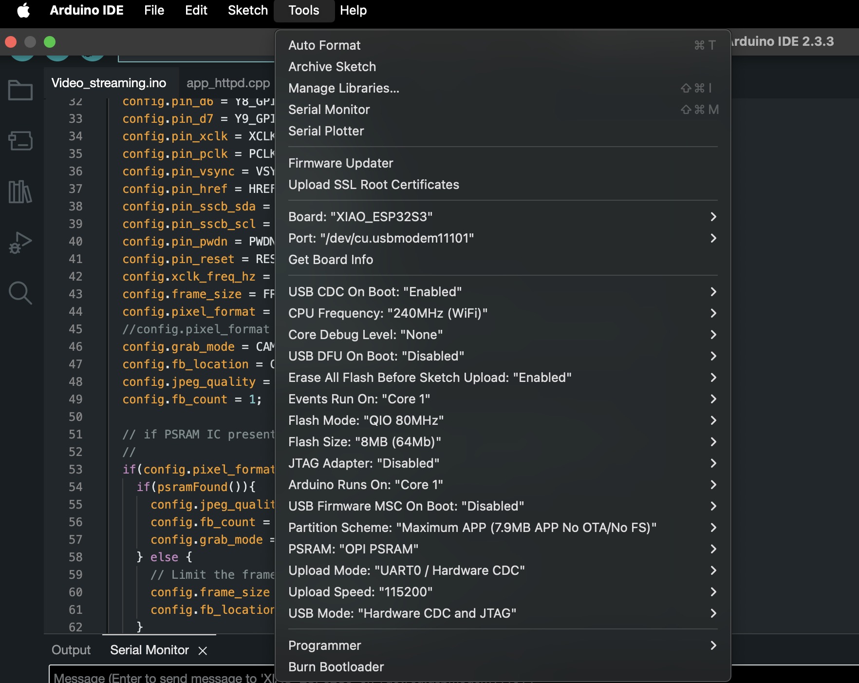
What worked was repeatedly erasing the flash drive through the terminal, by first "brew install esptool", then "esptool.py --chip esp32s3 --port /dev/cu.usbmodem11401 erase_flash", pressing BOOT button on the microcontroller while uploading code and pressing BOOT and RESET buttons to refresh the connections, reinstating ESP32 core from version 3.0.7 to 2.0.15 (per bug highlighted in the class gitlab's issue tracker), and toggling various settings under Arduino IDE> Tools (specifically: reducing Upload Speed to 115200, changing Partition to Maximum App, changing PSRAM from disabled to OPI PSRAM).
Shown here are the settings that worked for me.
Another key error I fixed was to ensure that the wifi username and password in both the code uploaded onto the microcontroller and the wifi I was using on my laptop (to display a browser showing the webcam stream) were the same. To ensure portability, I used my phone's hotspot instead of my home/ school/ lab's wifi credentials.
Full code below:
    #include "esp_camera.h"
    #include <WiFi.h>

    #define CAMERA_MODEL_XIAO_ESP32S3 // Has PSRAM

    #include "camera_pins.h"

    // ===========================
    // Enter your WiFi credentials
    // ===========================
    const char* ssid = "********";
    const char* password = "********";

    void startCameraServer();
    void setupLedFlash(int pin);

    void setup() {
      Serial.begin(115200);
      while(!Serial);
      Serial.setDebugOutput(true);
      Serial.println();

      camera_config_t config;
      config.ledc_channel = LEDC_CHANNEL_0;
      config.ledc_timer = LEDC_TIMER_0;
      config.pin_d0 = Y2_GPIO_NUM;
      config.pin_d1 = Y3_GPIO_NUM;
      config.pin_d2 = Y4_GPIO_NUM;
      config.pin_d3 = Y5_GPIO_NUM;
      config.pin_d4 = Y6_GPIO_NUM;
      config.pin_d5 = Y7_GPIO_NUM;
      config.pin_d6 = Y8_GPIO_NUM;
      config.pin_d7 = Y9_GPIO_NUM;
      config.pin_xclk = XCLK_GPIO_NUM;
      config.pin_pclk = PCLK_GPIO_NUM;
      config.pin_vsync = VSYNC_GPIO_NUM;
      config.pin_href = HREF_GPIO_NUM;
      config.pin_sscb_sda = SIOD_GPIO_NUM;
      config.pin_sscb_scl = SIOC_GPIO_NUM;
      config.pin_pwdn = PWDN_GPIO_NUM;
      config.pin_reset = RESET_GPIO_NUM;
      config.xclk_freq_hz = 20000000;
      config.frame_size = FRAMESIZE_UXGA;
      config.pixel_format = PIXFORMAT_JPEG; // for streaming
      //config.pixel_format = PIXFORMAT_RGB565; // for face detection/recognition
      config.grab_mode = CAMERA_GRAB_WHEN_EMPTY;
      config.fb_location = CAMERA_FB_IN_PSRAM;
      config.jpeg_quality = 12;
      config.fb_count = 1;

      // if PSRAM IC present, init with UXGA resolution and higher JPEG quality
      //                      for larger pre-allocated frame buffer.
      if(config.pixel_format == PIXFORMAT_JPEG){
        if(psramFound()){
          config.jpeg_quality = 10;
          config.fb_count = 2;
          config.grab_mode = CAMERA_GRAB_LATEST;
        } else {
          // Limit the frame size when PSRAM is not available
          config.frame_size = FRAMESIZE_SVGA;
          config.fb_location = CAMERA_FB_IN_DRAM;
        }
      } else {
        // Best option for face detection/recognition
        config.frame_size = FRAMESIZE_240X240;
    #if CONFIG_IDF_TARGET_ESP32S3
        config.fb_count = 2;
    #endif
      }

      // camera init
      esp_err_t err = esp_camera_init(&config);
      if (err != ESP_OK) {
        Serial.printf("Camera init failed with error 0x%x", err);
        return;
      }

      sensor_t * s = esp_camera_sensor_get();
      // initial sensors are flipped vertically and colors are a bit saturated
      if (s->id.PID == OV3660_PID) {
        s->set_vflip(s, 1); // flip it back
        s->set_brightness(s, 1); // up the brightness just a bit
        s->set_saturation(s, -2); // lower the saturation
      }
      // drop down frame size for higher initial frame rate
      if(config.pixel_format == PIXFORMAT_JPEG){
        s->set_framesize(s, FRAMESIZE_QVGA);
      }

    // Setup LED FLash if LED pin is defined in camera_pins.h
    #if defined(LED_GPIO_NUM)
      setupLedFlash(LED_GPIO_NUM);
    #endif

      WiFi.begin(ssid, password);
      WiFi.setSleep(false);

      while (WiFi.status() != WL_CONNECTED) {
        delay(500);
        Serial.print(".");
      }
      Serial.println("");
      Serial.println("WiFi connected");

      startCameraServer();

      Serial.print("Camera Ready! Use 'http://");
      Serial.print(WiFi.localIP());
      Serial.println("' to connect");
    }

    void loop() {
      // Do nothing. Everything is done in another task by the web server
      delay(10000);
    }
Next steps for if/ when I revisit this week's assignment: to try connecting 2 ESP32s, have input from a webcam trigger servo movement on another. Consulted TA Quentin and fellow classmate Kye, and some next steps I could consider include:
- Attach one of the ESP32s to a battery (lithium, or powerbank), to act as a remote control
- Use ESP-NOW for the ESP32s to talk to each other. Given storage limits, one probably cannot transmit live video streams, and Kye suggested parsing the input from the webcam into 1 and 0, i.e. 1 if a hand/ large mass covering x% of the camera is detected, else 0
