materials
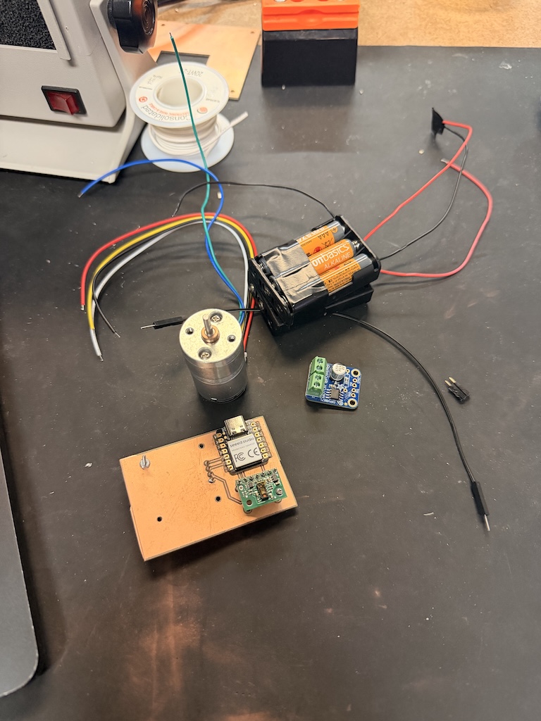
Hello! This week turned out a little crazy but perhaps slightly less crazy than I anticipated.During pcb production week, I wanted to use a motor and driver to prepare for my final project. I tried to use a DRV8847PWPR, but it was so tiny and I was unprepared.. I also did not realize the laser was an option to make the tiny traces at the time. So I ended up browsing adafruit and got a DRV8871 DC motor driver breakout board and a geared DC motor with a magnetic encoder.
I chose these because for my final project, I need multiple revolutions in both directions and want to be able PWM the speed. The motor also has a magnetic wheel and two Hall effect sensor to sense the rotation. I also thought these seemed pretty beginner friendly as I am still figuring everything out.
So I got started! I used the same board as last week because I did not want to waste the components on there and start again. I used a SEEED SAMD21, a Pololu TOF distance sensor, and an Oled screen. I wanted to hook up the motor and driver directly to this so that the distance could inform the activation of the motor.
I also used 6 AAA batteries in series to get 9V (the motor takes 7V).
I began soldering everything together, starting with the motor's wires. The blue goes to the microcontroller's 3.3V, black to GND. and yellow and white to any digital pin so I went with D7 and D8.
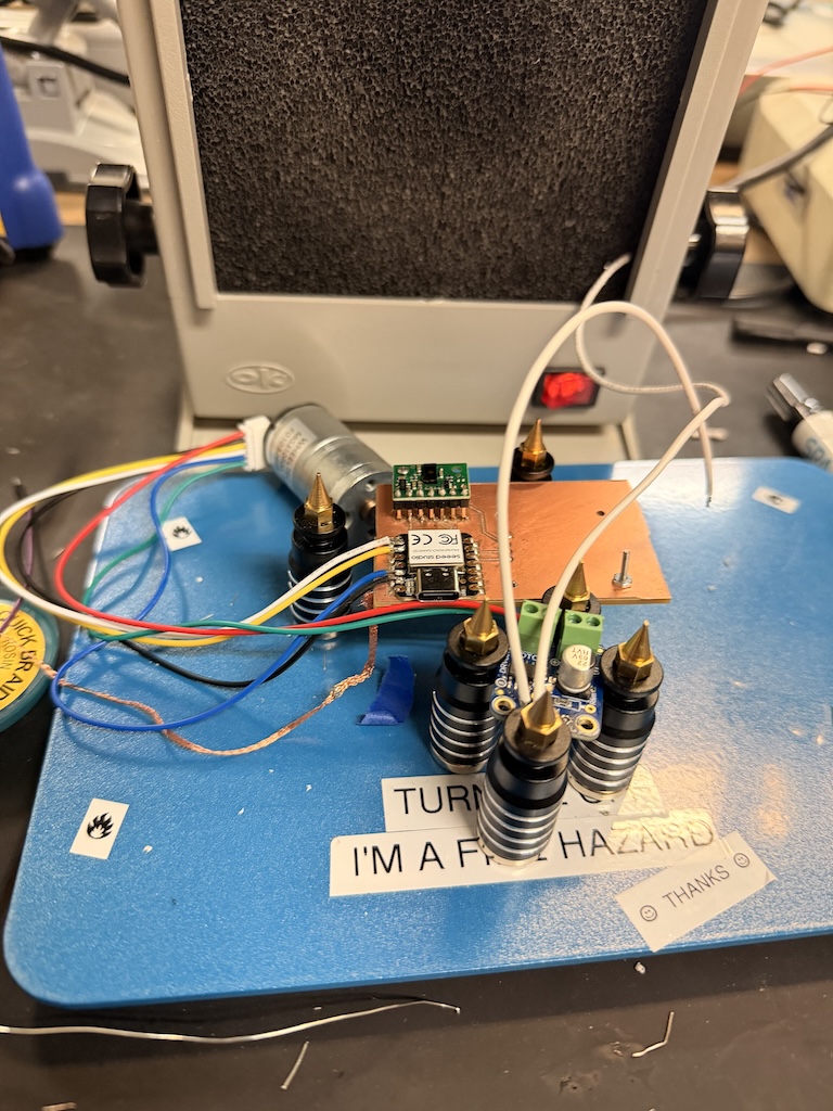
Yeah it looks crazy. I realized I should have prepared ahead and just made traces to my breakout board before, but oh well. I face the consequences of my actions. I started using these really thick wires to connect my driver's IN1 to my microcotroller.. which was a mistake. They were very hard to heat up and did not stick, and I ended up accidentally filling the GND pin with solder.
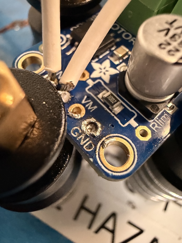
So that was annoying. But I just kind of stuck the end of the wire to the top of it and it seemed ok via multimeter. But then...once I soldered all of those onto the driver, I had to attach to the SAMD21. And this is where I panicked....
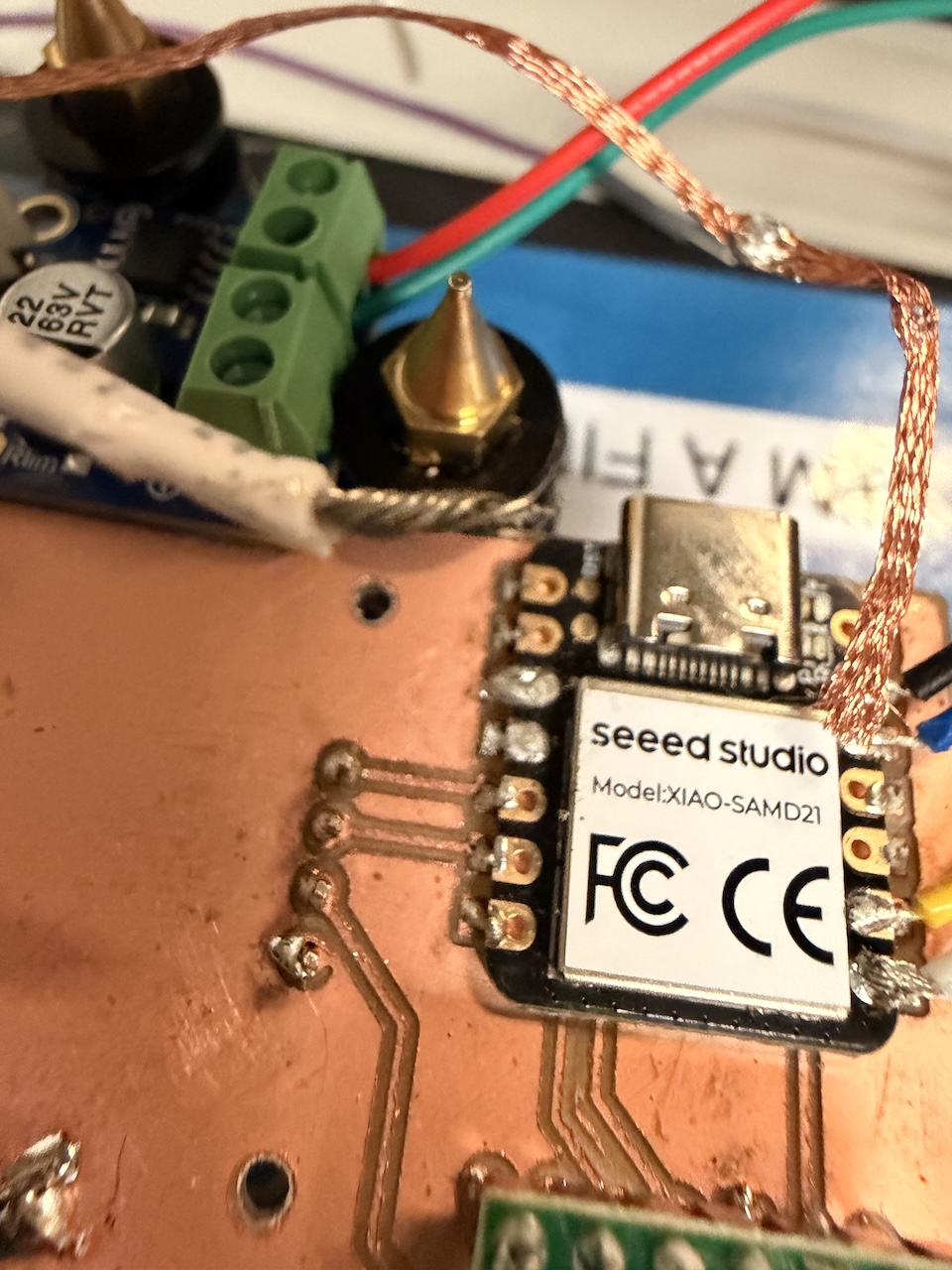
I tried adding them to D2 and D3 pins, but once I added them and tested with multimeter, I discovered they were connected to GND. NOOOOOOOOOOO!! So I desoldered the wires and contemplated. I could not really get the solder off of the pis successfully... so i kind of decided to just leave it and put them on different pins. I also changed wires to thinner ones because the white wires were SO thick.
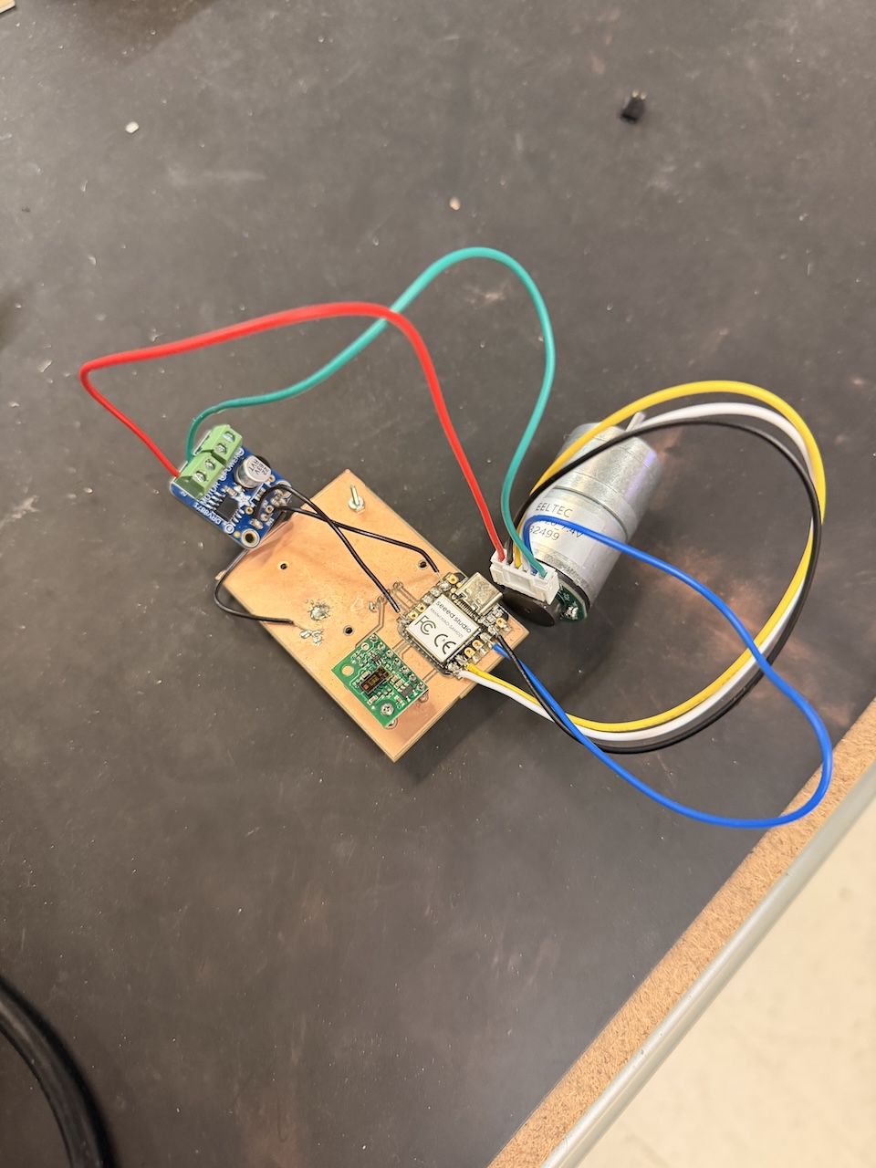
so here is the end result haha.... It looks crazy. but It works. The red and green wires go into the driver for Motor 1 and 2. I also just soldered the GND on the driver to a random spot on my GND plate.
Now for the moment of truth..... does it work......????!?!?!?!?!!!!
YES!!!!
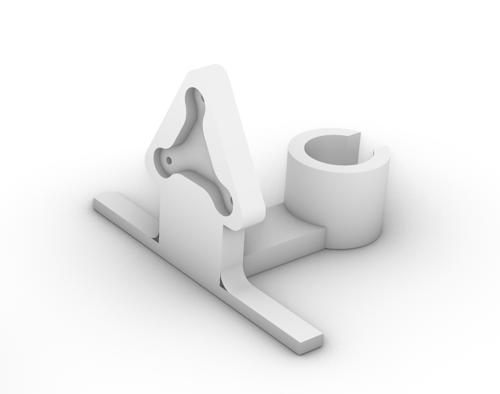
Somehow it actually worked on my first soldering try. I was honestly shocked. I also printed a little stand to put the motor in that will hold my tentacle as well.
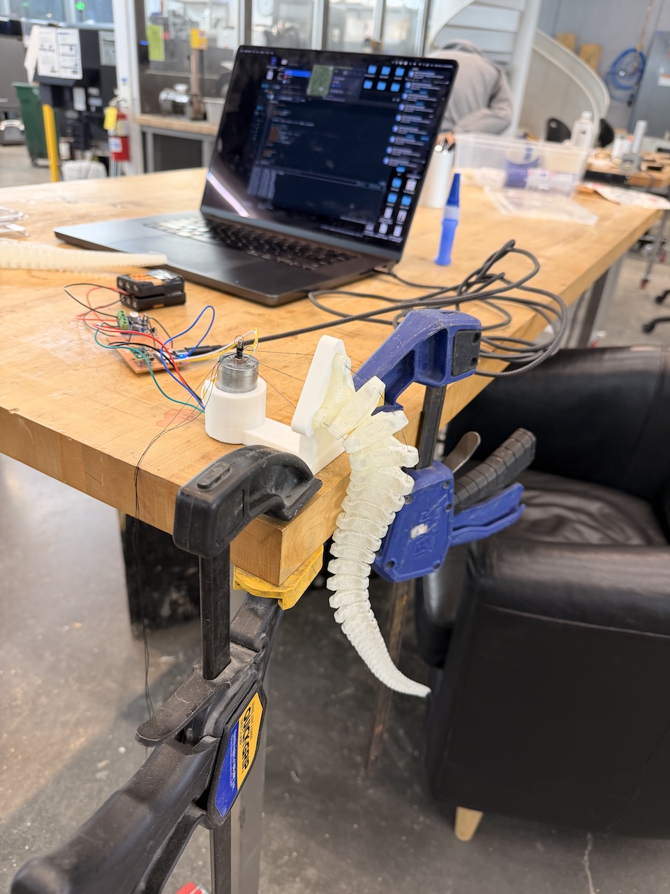
I hooked up my tentacle cables to the motor - the top one wrapping to the left and bottom two to the right. I think it was generally successful, but I will need to get better cables than just thread as it is quite weak.
Additionally, I am still working out connecting the sensor to the motor and having it activate at a certain distance. IF you are reading this, I haven't figured it out yet. But I will!!!
Here is the code I used for my motor test:
// ---- DRV8871 + SAMD21 + Encoder RPM ----
const uint8_t IN1_PIN = 1;   // DRV8871 IN1 (PWM-capable on many SAMD21s; change if needed)
const uint8_t IN2_PIN = 6;   // DRV8871 IN2
const uint8_t ENCODER_A = 7; // encoder A (white)
const uint8_t ENCODER_B = 8; // encoder B (yellow)

const float GEARING     = 20.0f; // gear ratio
const float ENCODERMULT = 12.0f; // ticks per motor rev (pre-gearbox)

// ISR state
volatile uint32_t lastA_us = 0;
volatile float rpm_inst = 0.0f;
volatile bool dirForward = true;

float rpm_smooth = 0.0f;
const float ALPHA = 0.20f; // smoothing 0..1

// --- ISR: NO IRAM_ATTR on SAMD21
void onEncoderA() {
  dirForward = digitalRead(ENCODER_B); // direction from other channel

  uint32_t now = micros();
  uint32_t dt;
  if (now >= lastA_us) dt = now - lastA_us;
  else                 dt = (0xFFFFFFFFu - lastA_us) + now + 1; // handle wrap

  if (dt > 0) {
    float rpm = (1e6f / (float)dt) * 60.0f; // rev/min at raw shaft
    rpm /= (GEARING * ENCODERMULT);         // account for gearbox & ticks
    rpm_inst = rpm;
  }
  lastA_us = now;
}

// Motor helper: speed in [-255..255]
void setMotor(int speed) {
  speed = constrain(speed, -200, 200);

  if (speed > 0) {
    analogWrite(IN1_PIN, speed);
    digitalWrite(IN2_PIN, LOW);
  } else if (speed < 0) {
    analogWrite(IN2_PIN, -speed);
    digitalWrite(IN1_PIN, LOW);
  } else {
    // Coast; for fast brake use HIGH/HIGH
    digitalWrite(IN1_PIN, LOW);
    digitalWrite(IN2_PIN, LOW);
  }
}

void setup() {
  Serial.begin(115200);
  // while (!Serial) { } // optional

  pinMode(IN1_PIN, OUTPUT);
  pinMode(IN2_PIN, OUTPUT);
  setMotor(0);

  pinMode(ENCODER_A, INPUT_PULLUP);
  pinMode(ENCODER_B, INPUT_PULLUP);
  attachInterrupt(digitalPinToInterrupt(ENCODER_A), onEncoderA, RISING);

  // Wait 10 seconds before starting
Serial.println("Waiting 10 seconds before start...");
delay(10000);  // 10,000 milliseconds = 10 seconds

  Serial.println("DRV8871 + Encoder on SAMD21");
}

void loop() {
  // demo ramp forward
  for (int s = 0; s <= 255; s += 3) { tick(s); }
  coastPause();
  // demo ramp reverse
  for (int s = 0; s <= 255; s += 3) { tick(-s); }
  coastPause();
}

void tick(int cmdSpeed) {
  setMotor(cmdSpeed);

  // smooth RPM
  rpm_smooth = ALPHA * rpm_inst + (1.0f - ALPHA) * rpm_smooth;

  static uint32_t t0 = 0;
  if (millis() - t0 > 50) {
    t0 = millis();
    Serial.print(dirForward ? "FWD " : "REV ");
    Serial.print("SPD=");
    Serial.print(abs(cmdSpeed));
    Serial.print("  RPM=");
    Serial.println((int)rpm_smooth);
  }
  delay(10);
}

void coastPause() {
  setMotor(0);
  delay(400);
}