Week 12: Networking & Communications
Group Assignment: Talking to Another Project
For the group assignment I wanted to connect my servo powered piston to somebody's control board. On my mechanical side is a 20 kg servo that winds a spool to pull a cable through a spring-loaded piston. This creates a linear motion strong enough to drive one of the Glowmorph lamp’s telescoping arms. I knew that Geoffery Hazard had a really succesful capacitive touch sensor with an up and down arrow and wanted to use that board to direct thepiston inwards and outwards.
We split the system into two boards: My motor dev board would be the receiver and Geoffery’s signal board would be the sender. Below are the sketches we used during the assignment: first we wanted to make sure that a signal sent through a data pin from Geoffery's board could be received. Then we would use this signal to cause the servo to move.
1A: Pin Reading (Adin's Side)
This initial sketch simply reads the two digital inputs and prints their states over Serial to confirm communication. It does not move the servo.
#include
#include

Adafruit_PWMServoDriver pwm = Adafruit_PWMServoDriver(0x40);

// Servo pulse limits for DS3218MG
#define SERVO_MIN 150   // approx 0.5 ms
#define SERVO_MAX 600   // approx 2.5 ms

// Pin Input Setup
const int PinPosInput = D2;   // Positive Sweep
const int PinNegInput = D3; // Negative Sweep

// Choose which PCA9685 pin your servo is on:
int servoChannel = 0;   // LEFT MOST PIN on your board

// Convert angle → PWM pulse
int angleToPulse(float angleDeg) {
  angleDeg = constrain(angleDeg, 0, 270);
  float pulse = SERVO_MIN + (angleDeg / 270.0f) * (SERVO_MAX - SERVO_MIN);
  return (int)pulse;
}

void setup() {

  // Initialize Serial communication
  Serial.begin(9600);
  while (!Serial) {
    ; // Wait for Serial to initialize (optional on some boards)
  }
  Serial.println("System initialized. Waiting for switch input...");

  Wire.begin();
  pwm.begin();
  pwm.setPWMFreq(50);  // Standard servo frequency
  delay(10);
  pinMode(PinPosInput, INPUT_PULLUP);
  pinMode(PinNegInput, INPUT_PULLUP);

}

void loop() {

// High means Positive
digitalRead(PinPosInput);

// High means Positive
digitalRead(PinNegInput);

// Send serial output
Serial.print("PinPosInput: ");
Serial.print(digitalRead(PinPosInput));
Serial.print("PinNegInput: ");
Serial.println(digitalRead(PinNegInput));

delay(200); // Small delay to make serial output readable


  // // FULL SWEEP – 0° → 270°
  // for (int a = 0; a <= 270; a += 3) {
  //   pwm.setPWM(servoChannel, 0, angleToPulse(a));
  //   delay(10); // tune your sweep speed
  // }

  // delay(500);

  // // SWEEP BACK – 270° → 0°
  // for (int a = 270; a >= 0; a -= 3) {
  //   pwm.setPWM(servoChannel, 0, angleToPulse(a));
  //   delay(10);
  // }

  // delay(700);
}
1B: Pin Sending (Geoffery's Side)
Geoffery’s sketch used two capacitive touch pads to set outputs on D2 and D3.
          #define PIN_RED 17
#define PIN_GREEN 16
#define PIN_BLUE 25

#define N_TOUCH 2
#define THRESHOLD 30

int touch_pins[N_TOUCH] = {3, 2};
int touch_values[N_TOUCH] = {0, 0};

//Define Pin Outputs
const int PinPosOutput = D2;   // Positive Sweep
const int PinNegOutput = D3; // Negative Sweep

bool pin_touched_now[N_TOUCH] = {false, false};
bool pin_touched_past[N_TOUCH] = {false, false};

void update_touch() {
  int t;
  int t_max = 200;
  int p;

  for (int i = 0; i < N_TOUCH; i++) {
    p = touch_pins[i];

    // set to low
    pinMode(p, OUTPUT);
    digitalWriteFast(p, LOW);

    // settle
    delayMicroseconds(25);

    // enable pull-up
    pinMode(p, INPUT_PULLUP);

    // measure time to rise
    t = 0;
    while (!digitalReadFast(p) && t < t_max) {
      t++;
    }
    touch_values[i] = t;

    // update state
    pin_touched_past[i] = pin_touched_now[i];
    pin_touched_now[i] = touch_values[i] > THRESHOLD;
  }
}

void print_touch() {
  char print_buffer[30];
  for (int i=0; i < N_TOUCH; i++) {
    sprintf(print_buffer, "%4d ", touch_values[i]);
    Serial.print(print_buffer);
  }
  Serial.println("");
}

void setup() {
  // initialize Serial port
  Serial.begin(0);
  pinMode(PinPosOutput, OUTPUT);
  pinMode(PinNegOutput, OUTPUT);

}

void loop() {
  // update the touch sensors
  update_touch();

  // Pin Output
  digitalWrite(PinPosOutput, HIGH);
  digitalWrite(PinNegOutput, HIGH);


  // example pressed button
  if (pin_touched_now[0] && !pin_touched_past[0]) {
    // button 0 was just pressed, do something
    digitalWrite(PIN_GREEN, LOW);
  }

  // example released button
  if (!pin_touched_now[0] && pin_touched_past[0]) {
    // button 0 was just released, do something
    digitalWrite(PIN_GREEN, HIGH);
  }

  // print values to Serial, for debugging
  print_touch();

  // slow down the loop to not print too fast (optional)
  delay(200);
}
2A: Moving the Piston (Adin's Board)
This final version drives the servo. A HIGH on
PinPosInput sweeps the servo forward (0°→270°); a HIGH on
PinNegInput
sweeps it back (270°→0°).
#include
#include

Adafruit_PWMServoDriver pwm = Adafruit_PWMServoDriver(0x40);

// Servo pulse limits for DS3218MG
#define SERVO_MIN 150   // approx 0.5 ms
#define SERVO_MAX 600   // approx 2.5 ms

// Pin Input Setup
const int PinPosInput = D2;   // Positive Sweep
const int PinNegInput = D3; // Negative Sweep

// Choose which PCA9685 pin your servo is on:
int servoChannel = 0;   // LEFT MOST PIN on your board

// Convert angle → PWM pulse
int angleToPulse(float angleDeg) {
  angleDeg = constrain(angleDeg, 0, 270);
  float pulse = SERVO_MIN + (angleDeg / 270.0f) * (SERVO_MAX - SERVO_MIN);
  return (int)pulse;
}

void setup() {

  Wire.begin();
  pwm.begin();
  pwm.setPWMFreq(50);  // Standard servo frequency
  delay(10);
  pinMode(PinPosInput, INPUT_PULLUP);
  pinMode(PinNegInput, INPUT_PULLUP);

}

void loop() {

// High means Positive
digitalRead(PinPosInput);

// High means Positive
digitalRead(PinNegInput);

if (digitalRead(PinPosInput)==1){

// SWEEP FORWARD – 0° → 270°
   for (int a = 0; a <= 270; a += 3) {
    pwm.setPWM(servoChannel, 0, angleToPulse(a));
    delay(10); // tune your sweep speed

  }
}

if (digitalRead(PinNegInput)==1){

  // SWEEP BACK – 270° → 0°
  for (int a = 270; a >= 0; a -= 3) {
    pwm.setPWM(servoChannel, 0, angleToPulse(a));
    delay(10);
  }
}
2b. Pad sending board (Geoffery's Board)
To fix the conflict between touch sensing and pin outputs, Geoffery moved the outputs to pins 6 and 7. This version simply sets pin 6 HIGH when the first pad is touched and pin 7 HIGH when the second pad is touched.
#define PIN_RED 17
#define PIN_GREEN 16
#define PIN_BLUE 25

#define N_TOUCH 2
#define THRESHOLD 30

int touch_pins[N_TOUCH] = {3, 2};
int touch_values[N_TOUCH] = {0, 0};

// Outputs TO MOTOR BOARD  (pick any spare pins NOT 2 or 3)
const int PinUpOutput   = 6;   // wire this to motor board D2
const int PinDownOutput = 7;   // wire this to motor board D3

bool pin_touched_now[N_TOUCH]  = {false, false};
bool pin_touched_past[N_TOUCH] = {false, false};

void update_touch() {
  int t;
  int t_max = 200;
  int p;

  for (int i = 0; i < N_TOUCH; i++) {
    p = touch_pins[i];

    // discharge
    pinMode(p, OUTPUT);
    digitalWriteFast(p, LOW);

    delayMicroseconds(25);

    // enable pull-up for timing
    pinMode(p, INPUT_PULLUP);

    t = 0;
    while (!digitalReadFast(p) && t < t_max) {
      t++;
    }
    touch_values[i] = t;

    // update state
    pin_touched_past[i] = pin_touched_now[i];
    pin_touched_now[i] = (touch_values[i] > THRESHOLD);
  }
}

void setup() {
  pinMode(PinUpOutput, OUTPUT);
  pinMode(PinDownOutput, OUTPUT);

  digitalWrite(PinUpOutput, LOW);
  digitalWrite(PinDownOutput, LOW);
}

void loop() {
  update_touch();

  // sensor 0 → UP output
  if (pin_touched_now[0]) {
    digitalWrite(PinUpOutput, HIGH);
  } else {
    digitalWrite(PinUpOutput, LOW);
  }

  // sensor 1 → DOWN output
  if (pin_touched_now[1]) {
    digitalWrite(PinDownOutput, HIGH);
  } else {
    digitalWrite(PinDownOutput, LOW);
  }

  delay(50);
}
From ToF Sensor to Networked 3D Model
This week’s assignment was to build a wired or wireless node with an addressable interface, and to send a message between two projects. I decided to turn my VL53L1X time-of-flight (ToF) sensor into a tiny networked “rangefinder” node that streams distance into Rhino/Grasshopper, where it controls a live model.
The long-term goal is to tie this into the Glowmorph lamp and its telescoping piston arms: distance in the world will map to extension of an inner shell, like a soft spatial barometer. For this week I focused on getting a clean, stable data link between the microcontroller and Grasshopper.
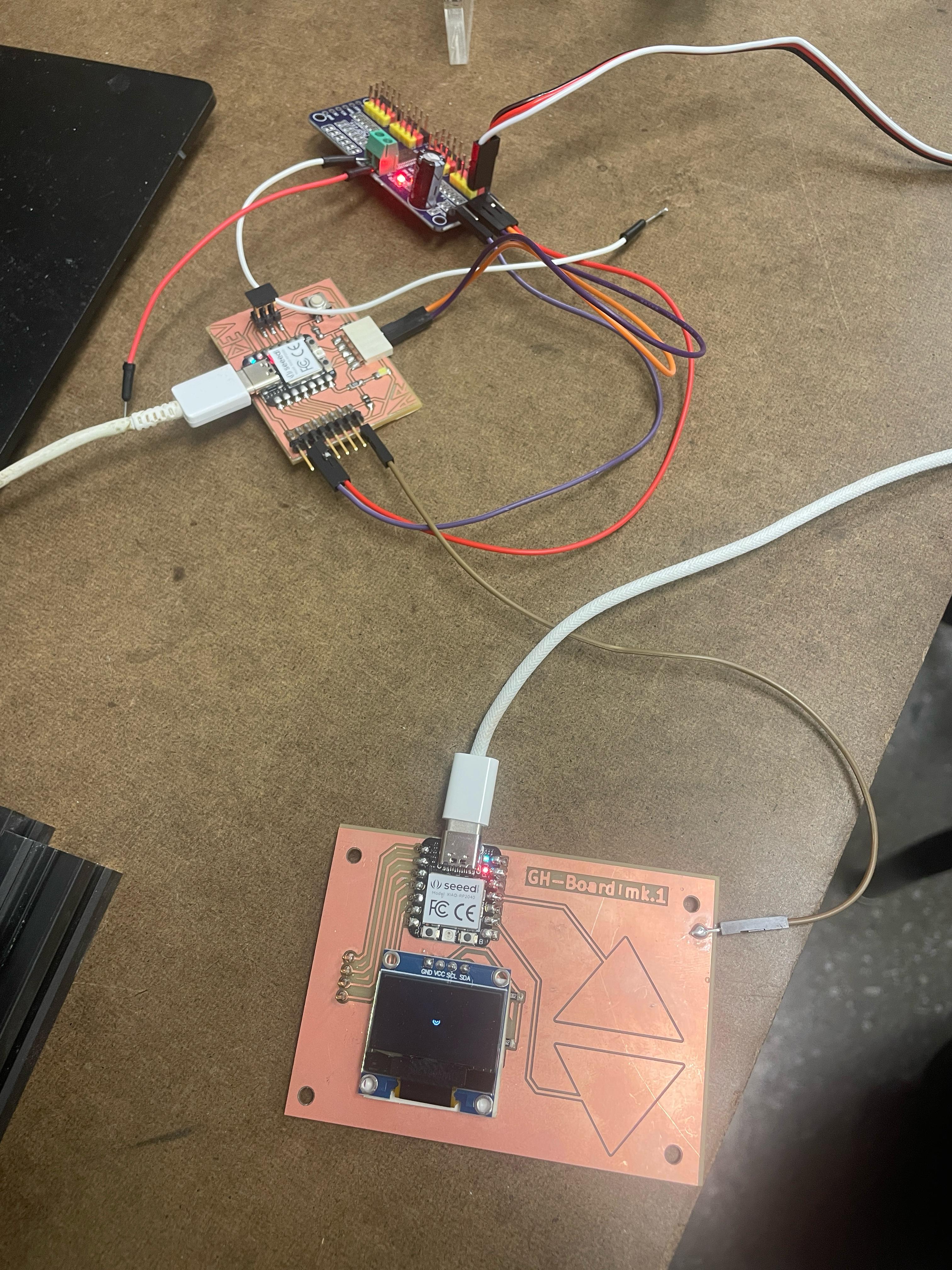
Node Hardware: XIAO RP2040 + VL53L1X
I used my custom XIAO RP2040 dev board from earlier weeks. The VL53L1X ToF sensor is wired to the I²C pins broken out along the bottom header. The node has one simple job: continuously measure distance and send it over serial as an ASCII message that I can parse on my computer.
Arduino / RP2040 Code
I used the Pololu VL53L1X library and formatted each
reading as a line that looks like D:123 (millimeters):
#include <Wire.h>
#include <VL53L1X.h>

VL53L1X sensor;

void setup() {
  Serial.begin(9600);
  Wire.begin();

  sensor.setTimeout(500);

  if (!sensor.init()) {
    Serial.println("VL53L1X init failed");
    while (1);   // hang if sensor is missing
  }

  sensor.setDistanceMode(VL53L1X::Long);      // better range
  sensor.setMeasurementTimingBudget(50000);   // 50 ms
  sensor.startContinuous(50);                 // ms between readings
}

void loop() {
  int distance = sensor.read();

  if (sensor.timeoutOccurred()) {
    distance = -1;  // mark out-of-range
  }

  Serial.print("D:");
  Serial.println(distance);  // e.g. D:206

  delay(10);
}
I wanted to stream distance as plain numbers into the the Arduino serial monitor and then point Grasshopper at the same port once everything looked stable using Firefly's Firefly Walkthrough.
Talking to Rhino with SuperSerial
After a bit of research, I noticed that Firefly is no longer maintained. Looking for alternatives, i found other people had similar issues and so Fabio D'Agnano a new plug-in the SuperSerial. Using the walkthrouguhs on their Food4Rhino website, I was able to arrange a simple script. The setup was:
- Port: COM12
- Baud: 9600 (to match
Serial.begin) - Mode: 0 – read-only
The Received output of SuperSerial gives me each line
as text, e.g. D:82. From there the Grasshopper definition
is just string parsing and remapping.
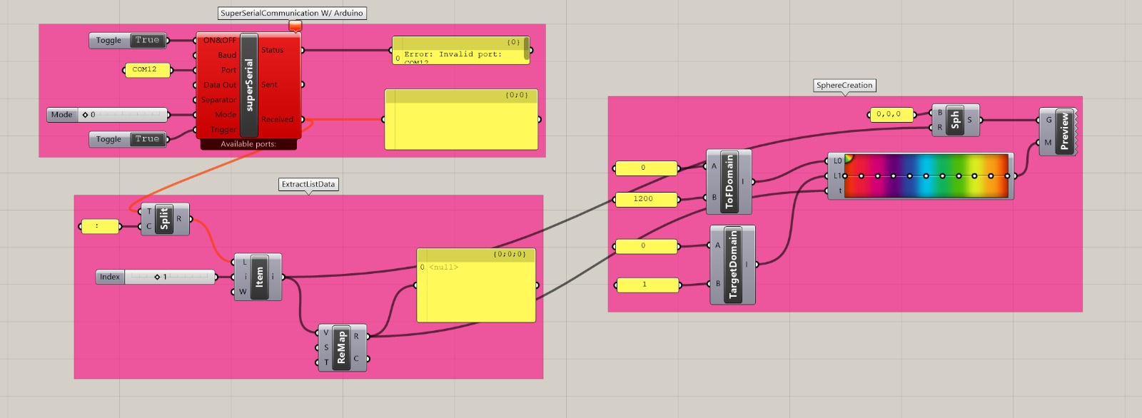
Mapping Distance to Geometry
As a first experiment I mapped distance measured with the ToF sensor to theradius and color of a sphere at the Rhino origin. Standing close to the sensor scales up the sphere and turns it bright orange, whereas stepping back shrinks it into a small blue dot. It’s a very simple mapping, but already feels like a spatial instrument: I’m effectively modeling Rhino by moving through the physical room. It's simple but was pretty exciting to me.
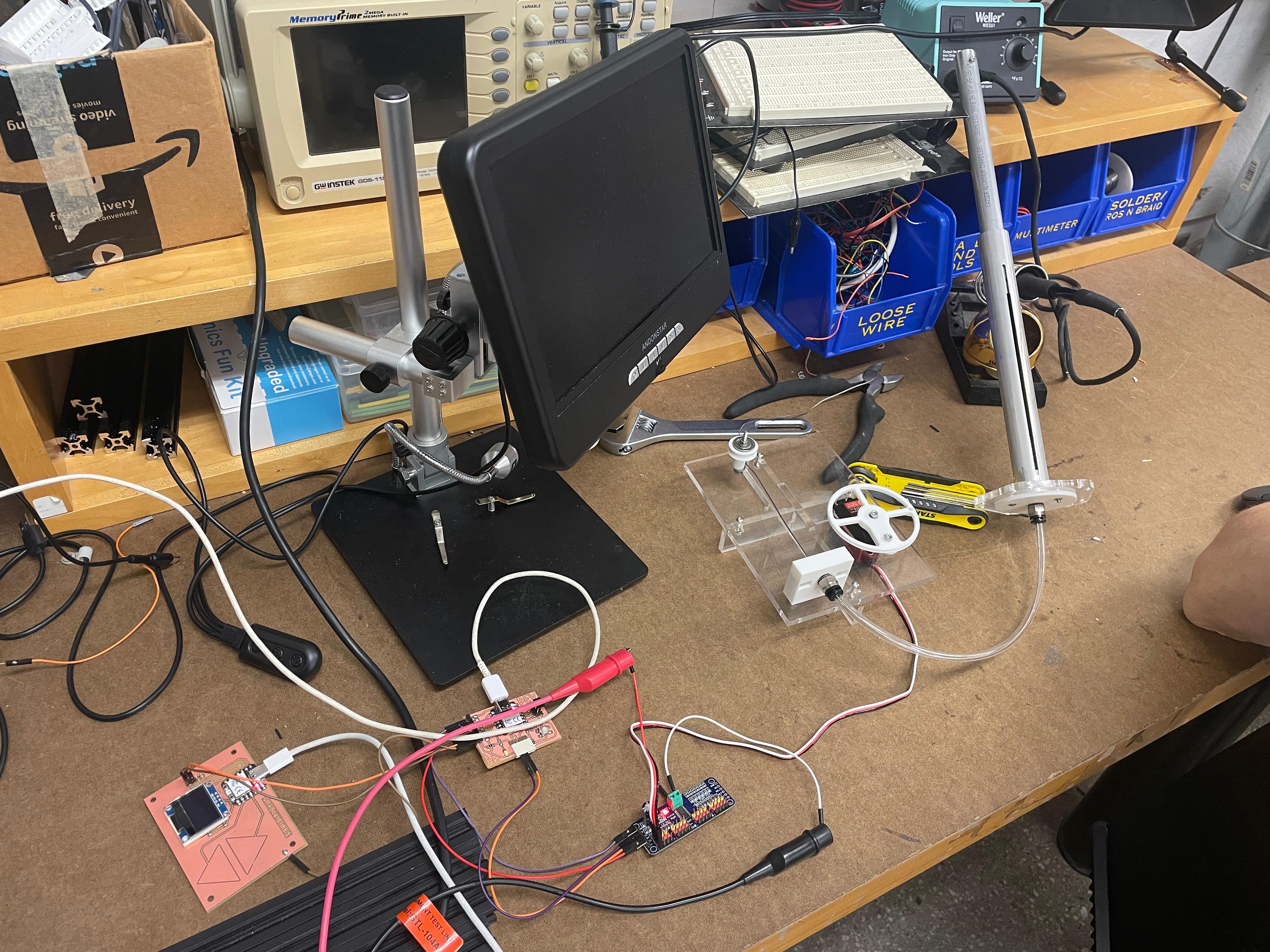
Testing a Simulation of the Sensor - Motor Behavior
Next, I mapped the sensed distance to a scaled amount of piston travel. My assumption was that this higher-fidelity behavior would feel more compelling, but in practice the motion was a little too sharp and reactive. It made me rethink whether this kind of direct sensing is right for the final project. Regardless, it was a useful study and helped clarify what’s actually working in the interaction.
Reflections
- The biggest debugging hurdle wasn’t code, it was COM-port ownership—only one program can open the port at a time.
- Keeping the node “dumb but reliable” (just measure and stream) is a good pattern. Higher-level behavior can live on the laptop in Rhino or Python.
- Proper power and wiring are as critical as code; replacing a flaky USB cable solved most of our communication issues.
- The PCA9685 breakout made it trivial to control a high-torque servo from a small RP2040:contentReference[oaicite:4]{index=4}.