Week 4 - 3D Scanning and Printing
3D Printing
I started this week by learning how to print, dialing in our settings, figuring out the best way to create adhesion to the plate. I want to push the final project idea I have, and so I wanted to start outputting prototypes to test different forms and first principles of assembly.
Group Assignment: "test the design rules for your 3D printer(s)"
Great. Let's run all the 3D Printing tests to help guide us on how to use the printer, and how to plan around overhangs, tolerances, adhesion, etc. After getting a walkthrough by Gert, we were off to the races. We printed all of the tests provided here: 3D Printing Tests.
I have provided all of the steps to print and some key principles to keep in mind in our shared web page though this link, but I will summarize what I did and reflect on what I learned by doing here. This summary is provided by ChatGPT, but will be furnished with additional takeaways and images. ChatGPT chat available here.
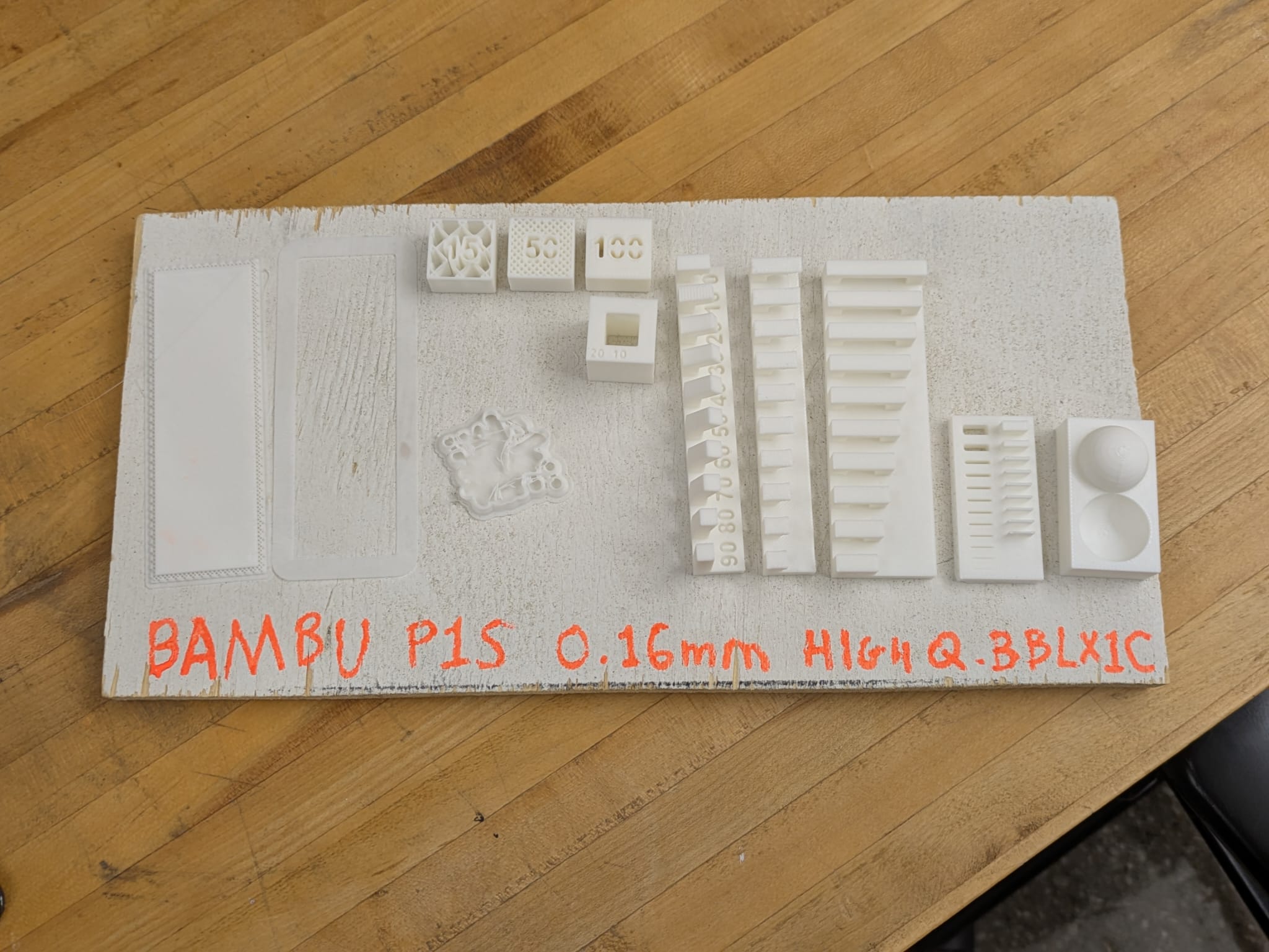
We printed all the tests and have relocated it to the lab so that everyone in the Architecture Group can reference it.
Week 3 Printing Steps & Major Takeaways
Steps Taken to Print / Test:- Consulted TA and lab documentation on the Bambu printers.
- Installed Bambu Studio slicer software and configured recommended settings (0.16mm “High Quality”).
- Decided on raft vs brim depending on object geometry.
- Adjusted infill density for strength vs material efficiency.
- Prepared filament spool and verified recognition by printer.
- Exported model to STL/3MF format, then sliced to G-code.
- Printed test objects to evaluate tolerances, overhangs, bridges, wall thickness, and surface finish.
- Documented failures and adjusted settings iteratively for reliability.
- Clearances & moving parts: gaps below ~0.3mm may fuse.
- Printable angles: >10° prints reliably.
- Overhangs & bridges: >6–7mm show drooping; short spans work well.
- Wall thickness: <0.3mm unreliable; ≥0.4mm safe.
- Dimensional accuracy: reliable to ~0.5mm.
- Surface finish: layer stepping noticeable near top layers.
- Infill: ~15% sufficient for many functional parts; higher infill often unnecessary.
- Brim vs raft: brims ≥7mm improve adhesion; rafts less reliable.
- Object-level overrides: infill and settings can be customized per object in a print job.
- Iterative testing is critical to understand machine limits and design within them.
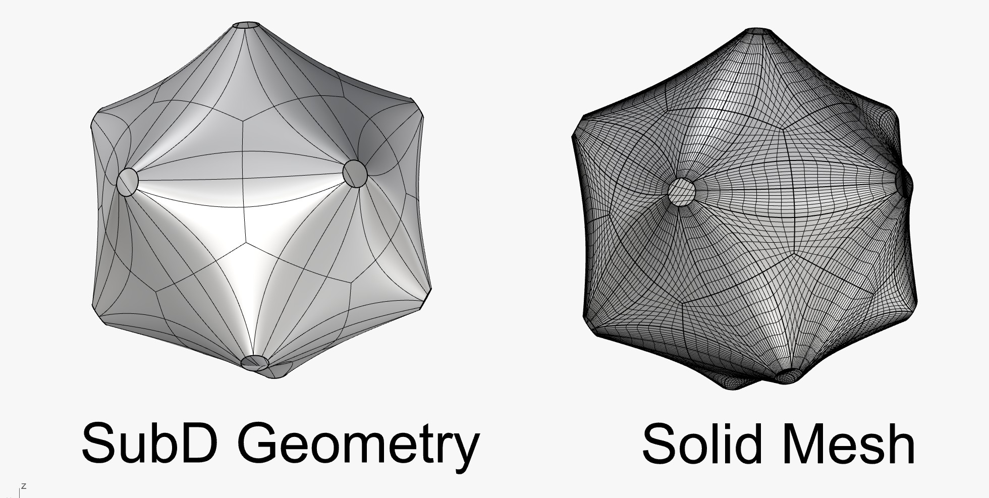
I turned a TSPline geometry in Rhino into a mesh and then exported it at a low face count so that it would print relatively quickly.
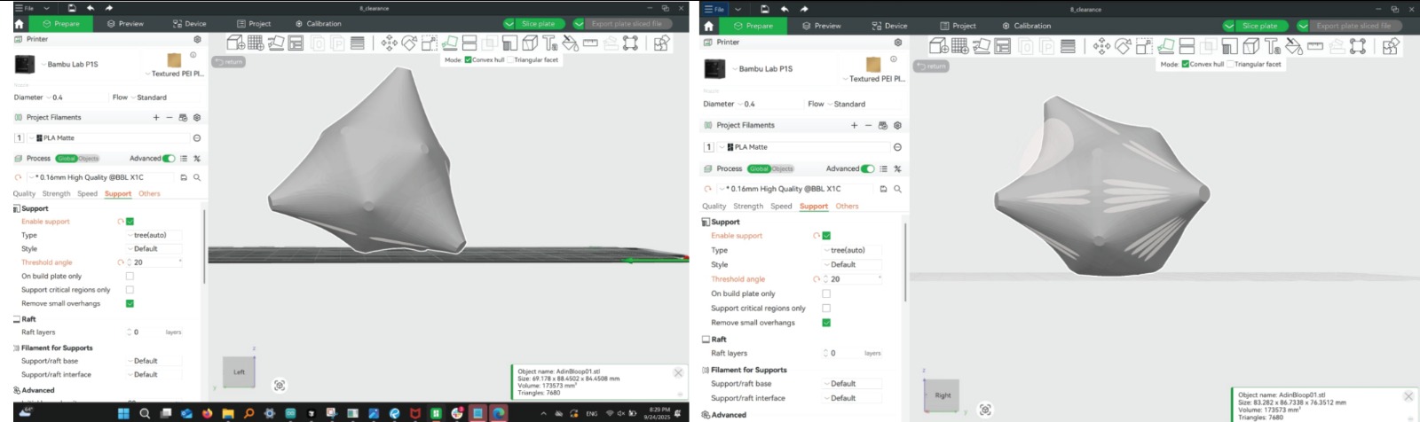
The two images above are showing me trying to figure out the best orientation to print my little guy.
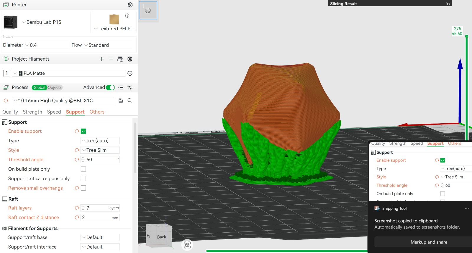
The image above is showing the Bambu Studio slicing software demonstrating the tool path
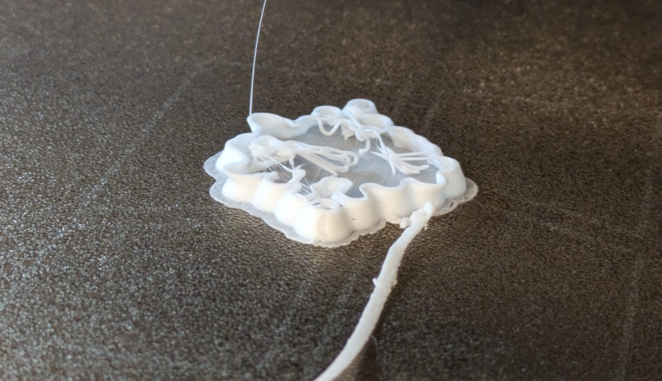
Above is an unsuccesful bed adhesion. We went with the brim which seemed fine, but our support angle tolerance was too low - less than 15 percent
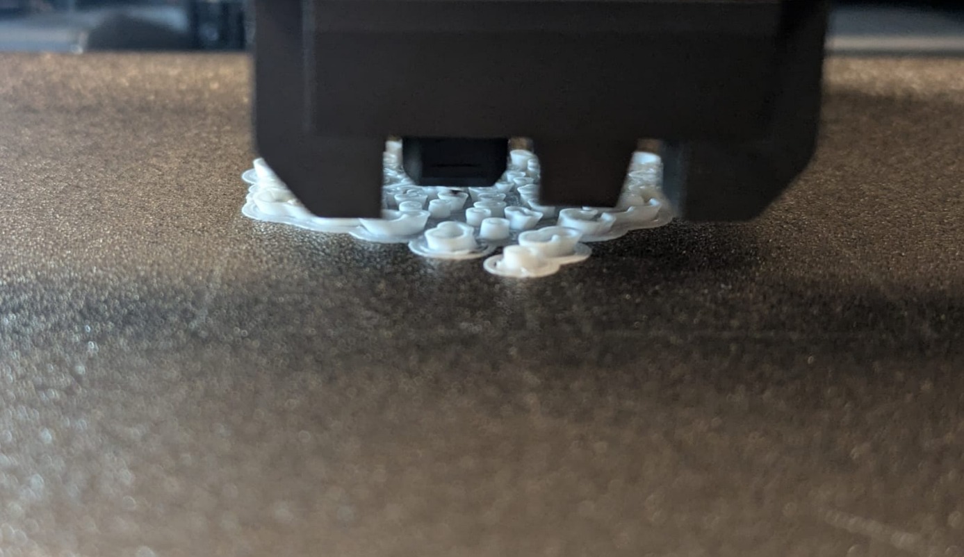
That's more like it! Above is an succesful bed adhesion. I changed the print tolerance to above 40
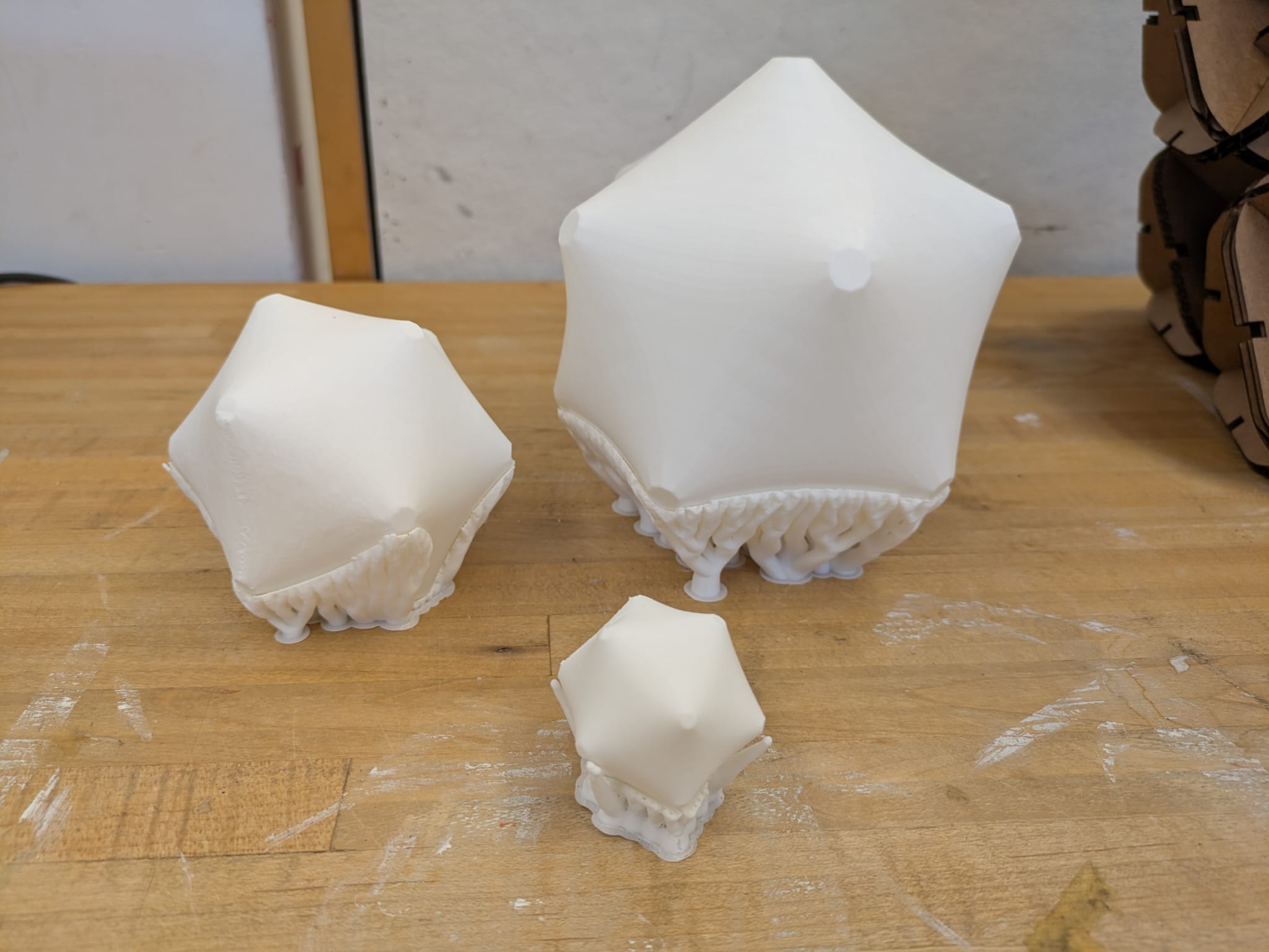
In the end, I ended up printing 3 different sizes, to see if there would be a relationship between object size and quality of print. I found that the larger the print, the easier the final was to remove from the supports.
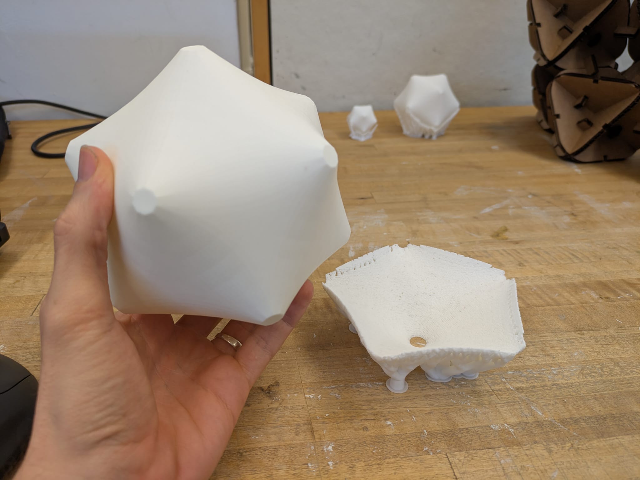
In the end, I ended up printing 3 different sizes, to see if there would be a relationship between object size and quality of print. I found that the larger the print, the easier the final was to remove from the supports.
Scanning
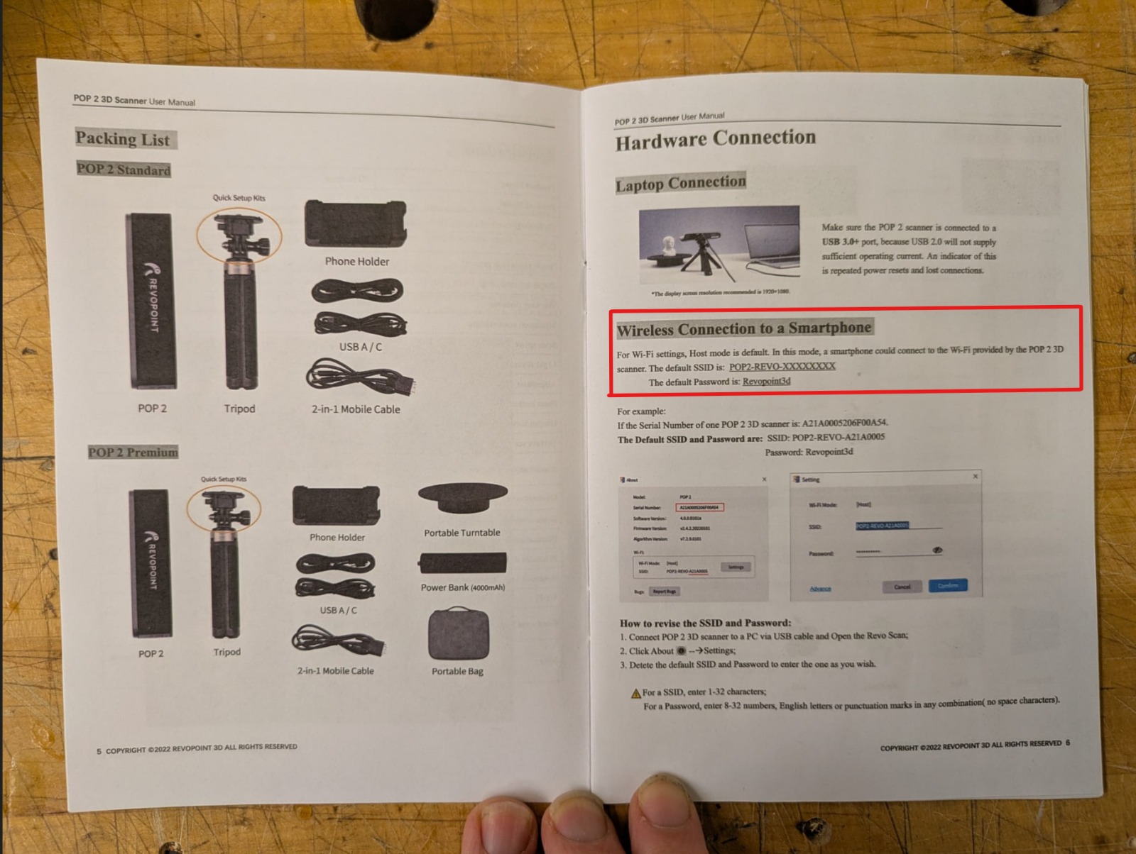
To scan, we used the Revopoint Pop 2 3D Scanner. It is a compact 3D scanner that uses dual infrared (IR) cameras and a projector to project a structured light (infrared pattern) onto the object, from which depth is inferred. It also has an RGB camera so that the resulting 3D mesh can carry color / texture information.
Instructions for use
For any additional questions, it's best to consult the official MIT Arch page here: Tutorials
So I tried to scan two things I believed to be difficult. One was a pile of chains I found, and the other was a bottle of San Pellegrino. The chains were interesting because I wanted to guage the depth that it could model out. The bottle was interesting because it's transparent, and the shortcoming of a lot of scanners is an inability to scan anything 3D.
Scanning Object: Chains
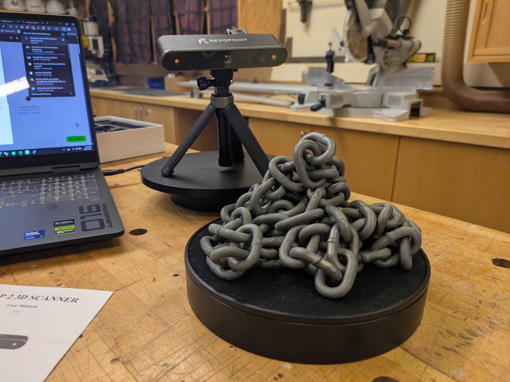
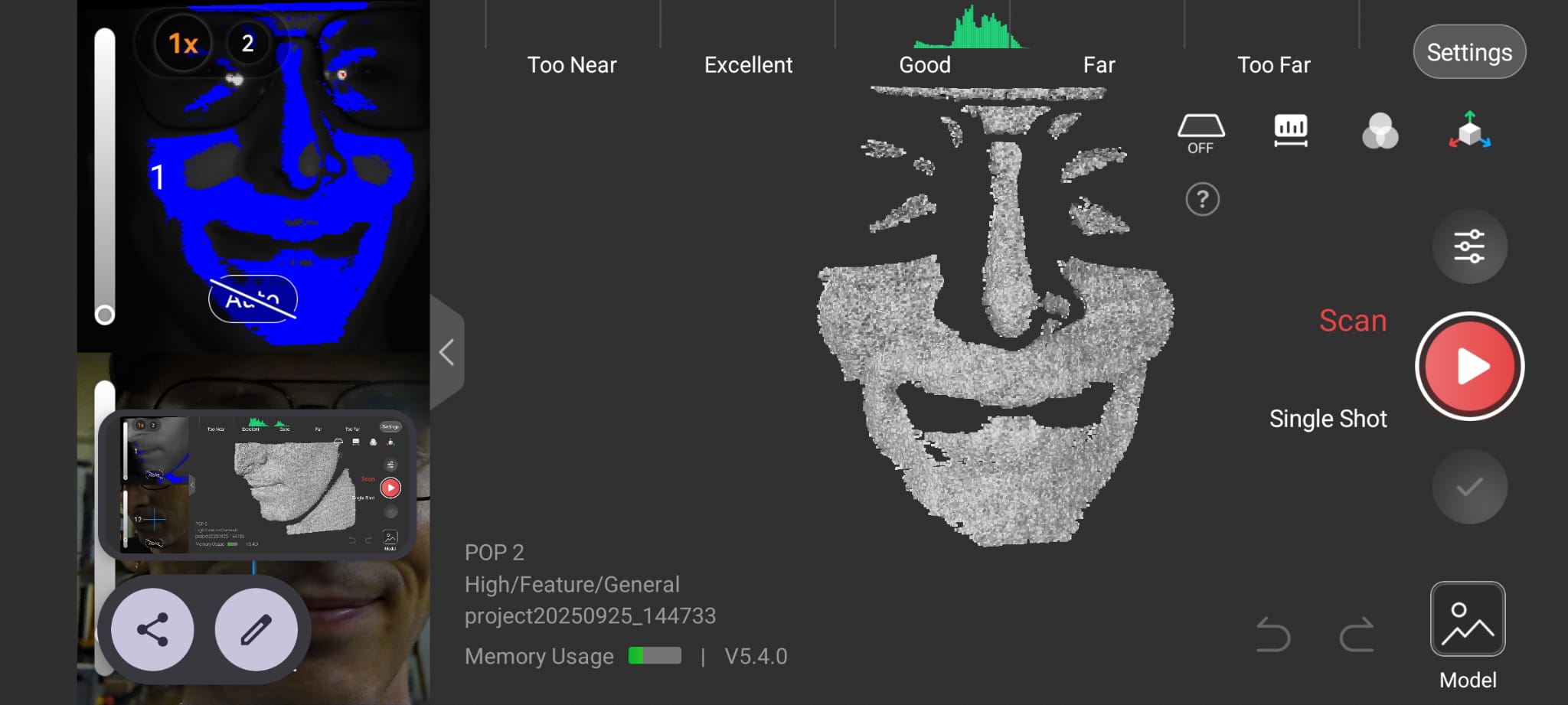
Above is a photo of the setup. The chains are on the rotating platform, and we kept the scanner in a fixed position.

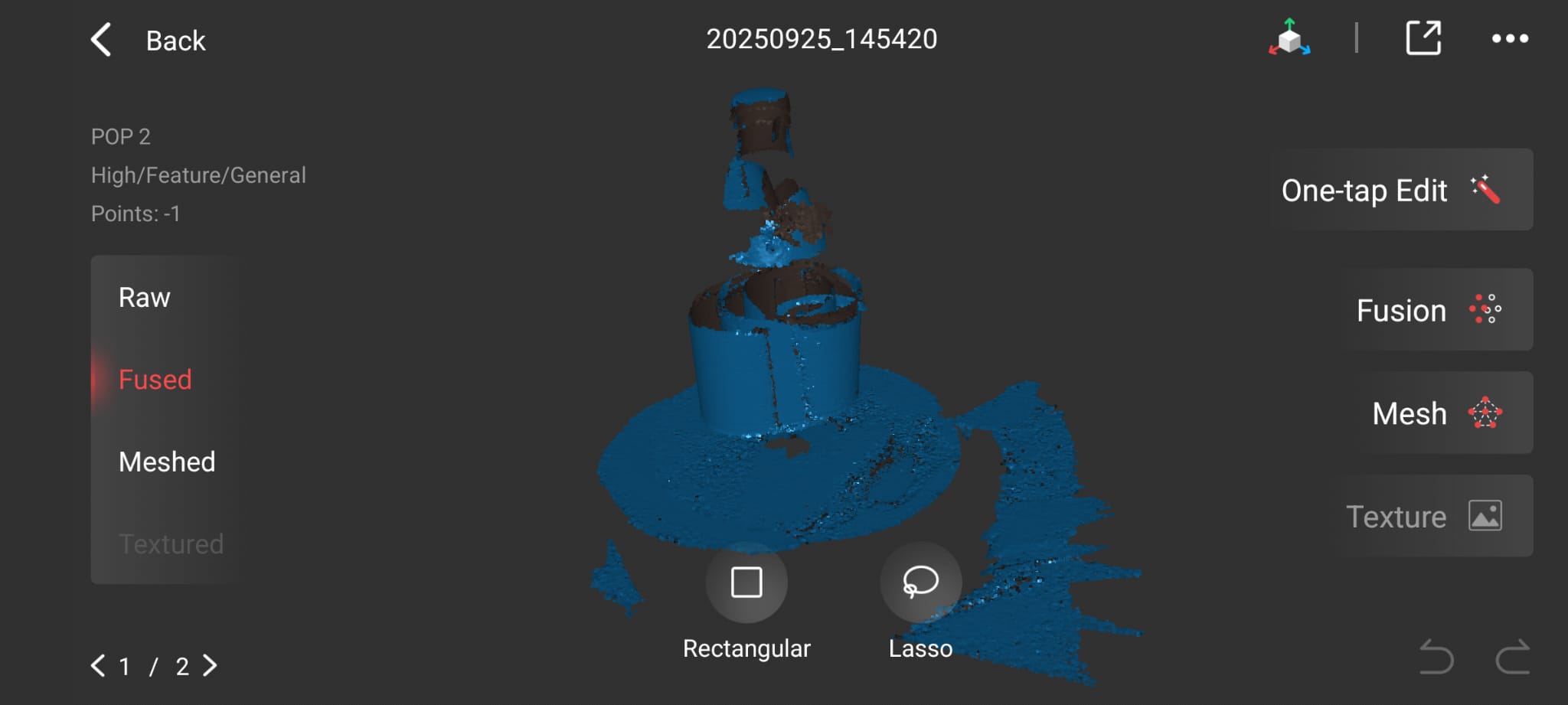
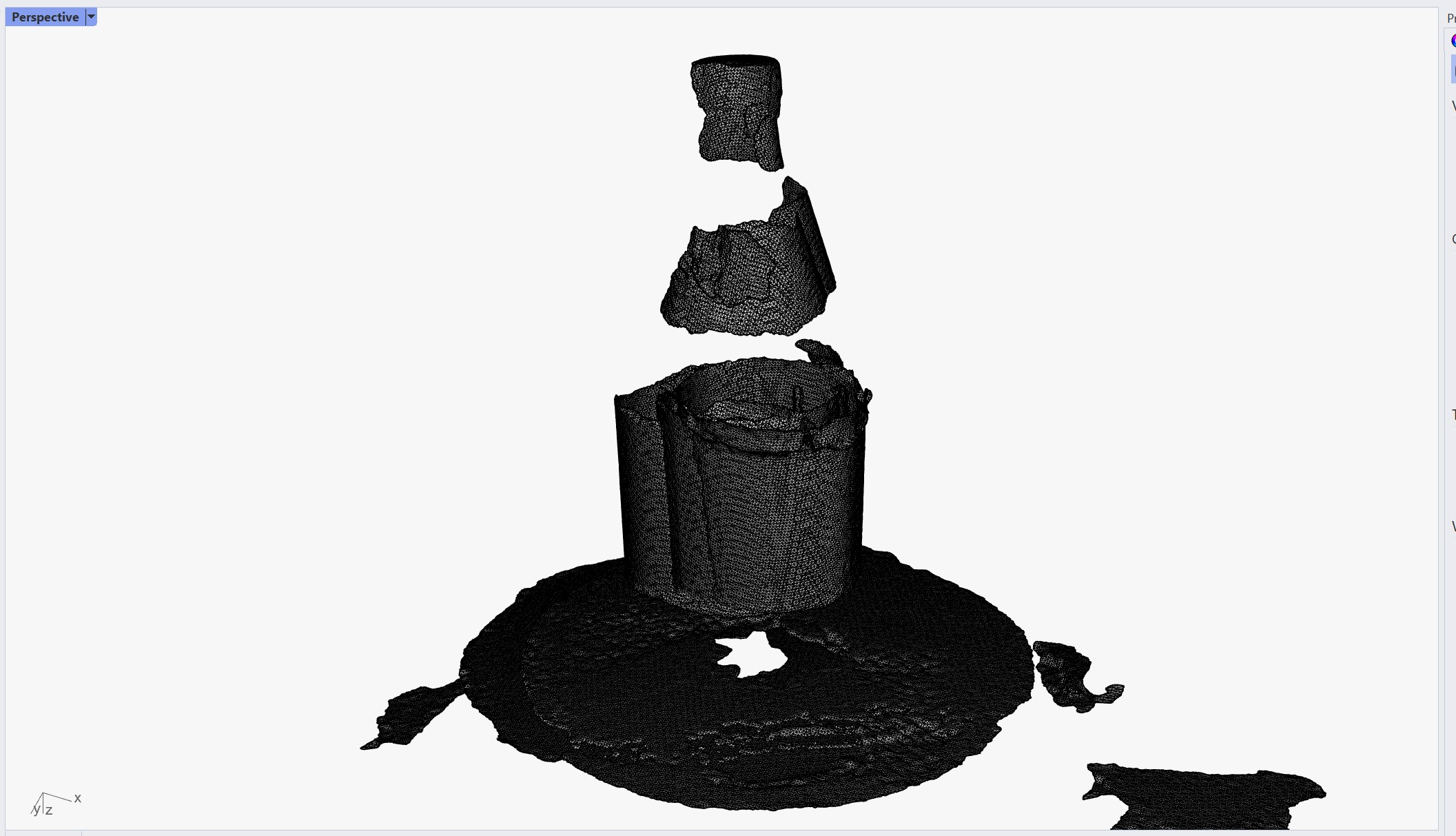
Above showing what came out of the app. You can see a good amount of "dark spaces", not meshed interior areas.

In-software slicer is making sense of the object through refinement processes. Definitely not water-tight, and would be a pain to do so.
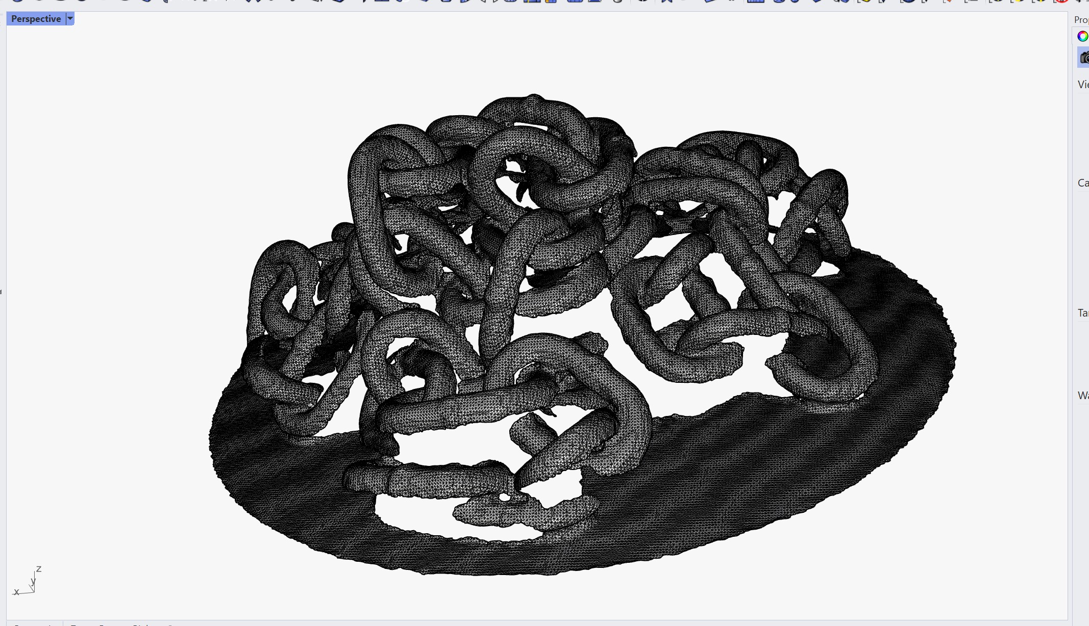
The chains came out better than anticipated. Unfortunately a lot of internal details within the pile was lost, but that was to be expected. As this was my first scan, I wanted to test the Revopoint 2 Pop 3D scanner against my phone. For the scanner, I used the Revo Scan software, whereas with my phone, I used Polycam which is a software I was using in the past.
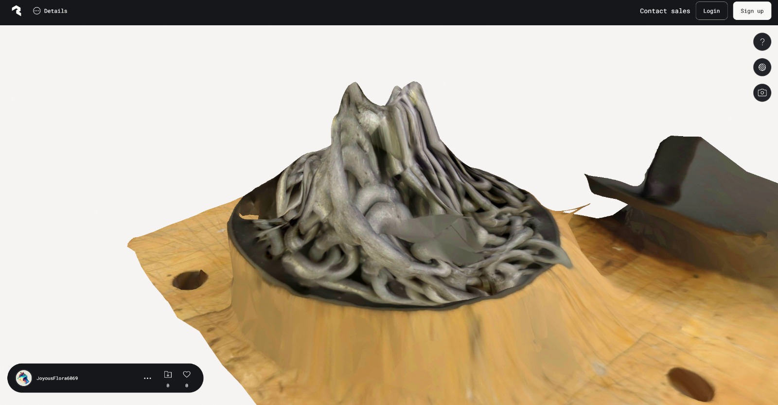
Above is the output from Polycam which I wanted to test as an alternative to Revo Scan. This was processed with the highest quality. Unfortunately, it looks pretty bad.
Scanning Object: Transparent Bottle

The bottle was a bit trickier. I noticed immediately, that anything transparent was invisible. Anything opaque such as the bottle top, or sticker would float in space. Moving the scanner back, I noticed that the parts were doubling up, and the environment eventually started spinning as well. Below are my results
Scanner Selfie!
For fun. Not vain enough to make a bust of myself, but I did consider turning myself into a chia pet for a few moments.
Scanning Objects & Observations
- Chains: Internal details partly lost, but overall shape captured well. Tested against Polycam on phone — phone scan quality lower.
- Transparent Bottle: Scanner struggled; transparent parts invisible, floating surfaces, environment artifacts appeared. Highlights scanner limitations.
- Selfie Scan: Fun experiment to test scanner capabilities and workflow.
Kinetic Parts Printing
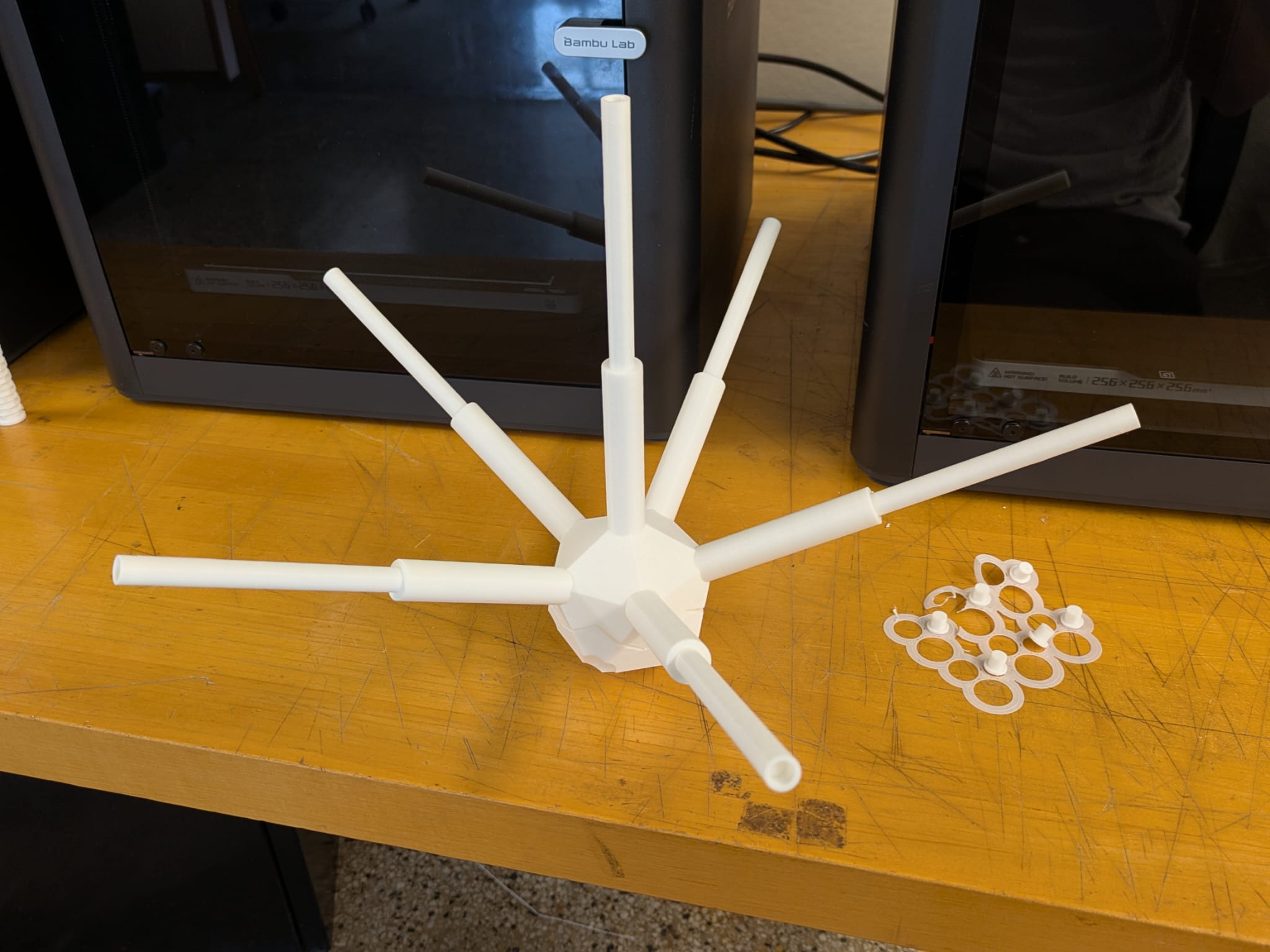
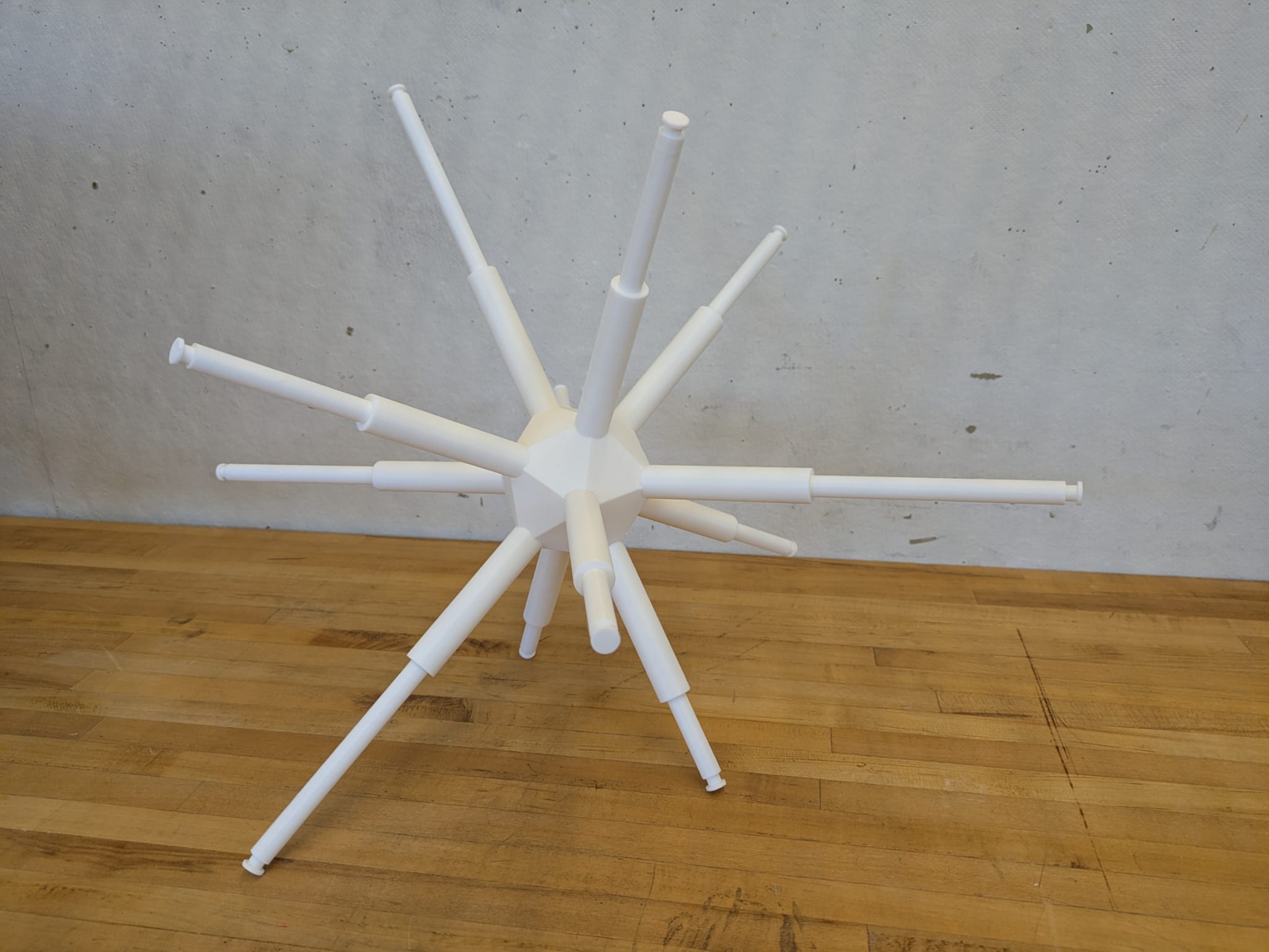
I wanted to use the 3D printing week as a moment to develop further my final project by picking up techniques, and measuring tolerances which I can use to design with. My idea is to use linear actuators for the final, but to keep things simple I went with a sort of kinetic 3d-printed piston. It would comprise of a chamber, inner arm, adaptor head and back enclosure. This presented a good opportunity to try out tolerances!
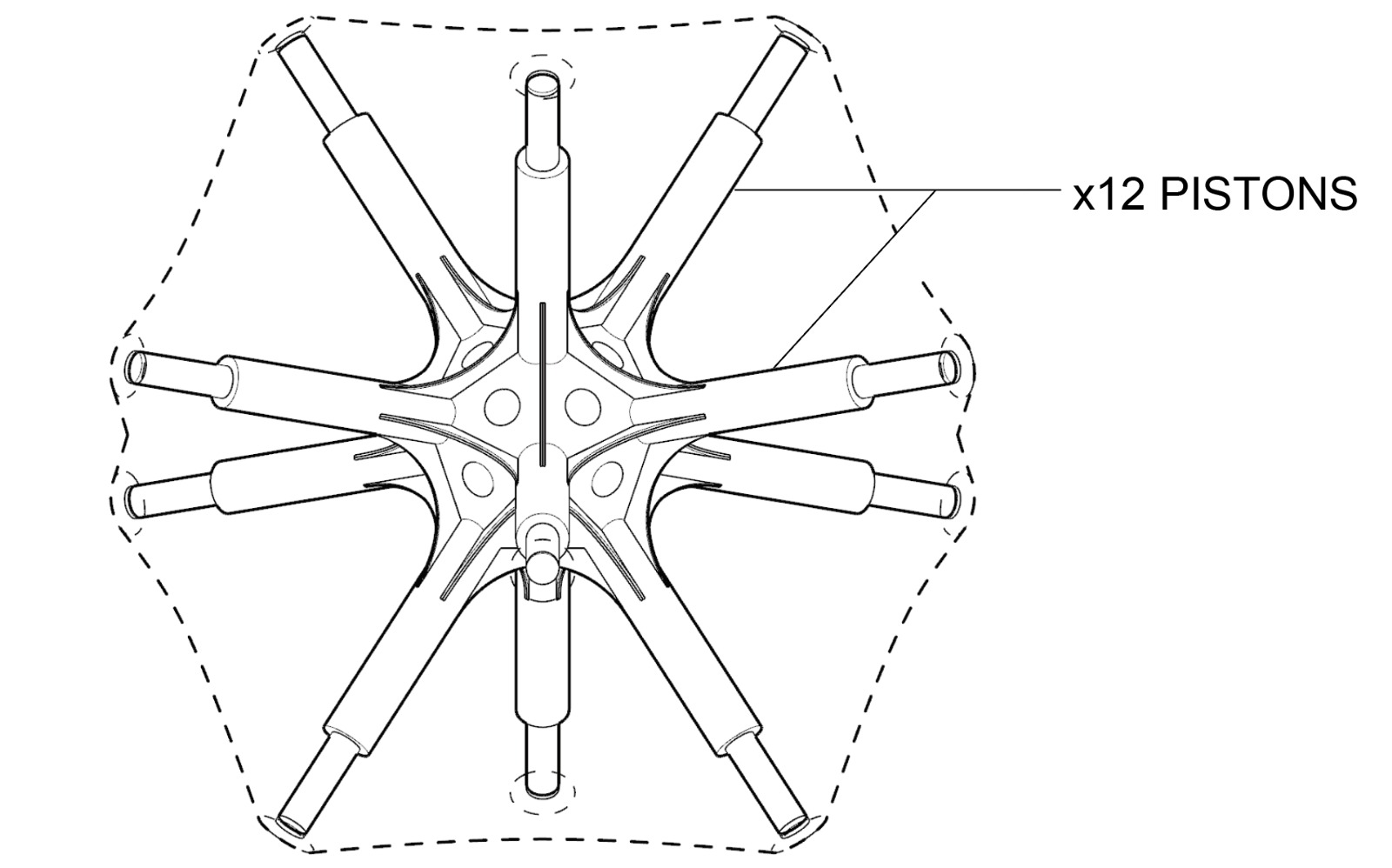
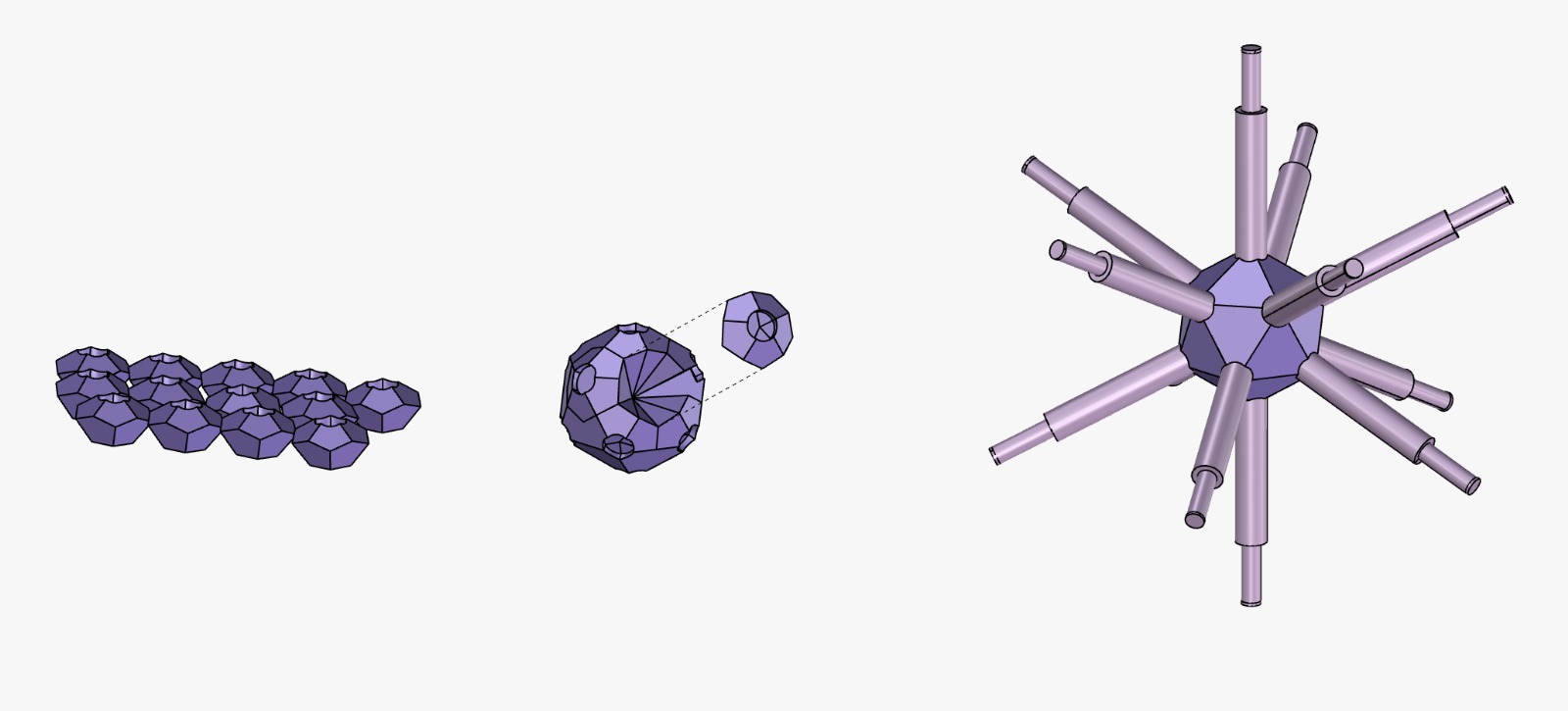
Above is demonstrating the latest final design with locations of linear actuator/pistons. In the imagined final design are arrayed are 11/12 pistons on a Icosohedron grid along its corners which push a tensile membrane out. In order to prototype the lamp, I needed to isolate these moments to try 3D printing.
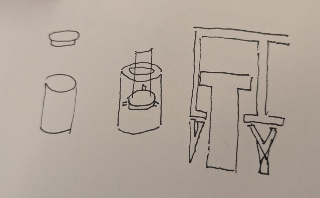
The above sketches are from Gert. He helped me brainstorm how to 3D print kinetic piston mechanisms that would be able to be printed either in one part or several parts and get assembled.
I tried several offsets to get parts that could slide within one another. I knew it should not be too loose, otherwise it'll wobble, and too tight, otherwise it wont move. I found that .05mm on both sides, or .1mm offset between tubular parts was the perfect amount - when printed perpindicular to the print bed.
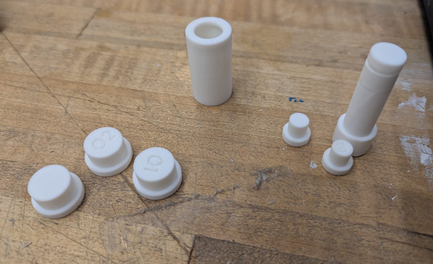
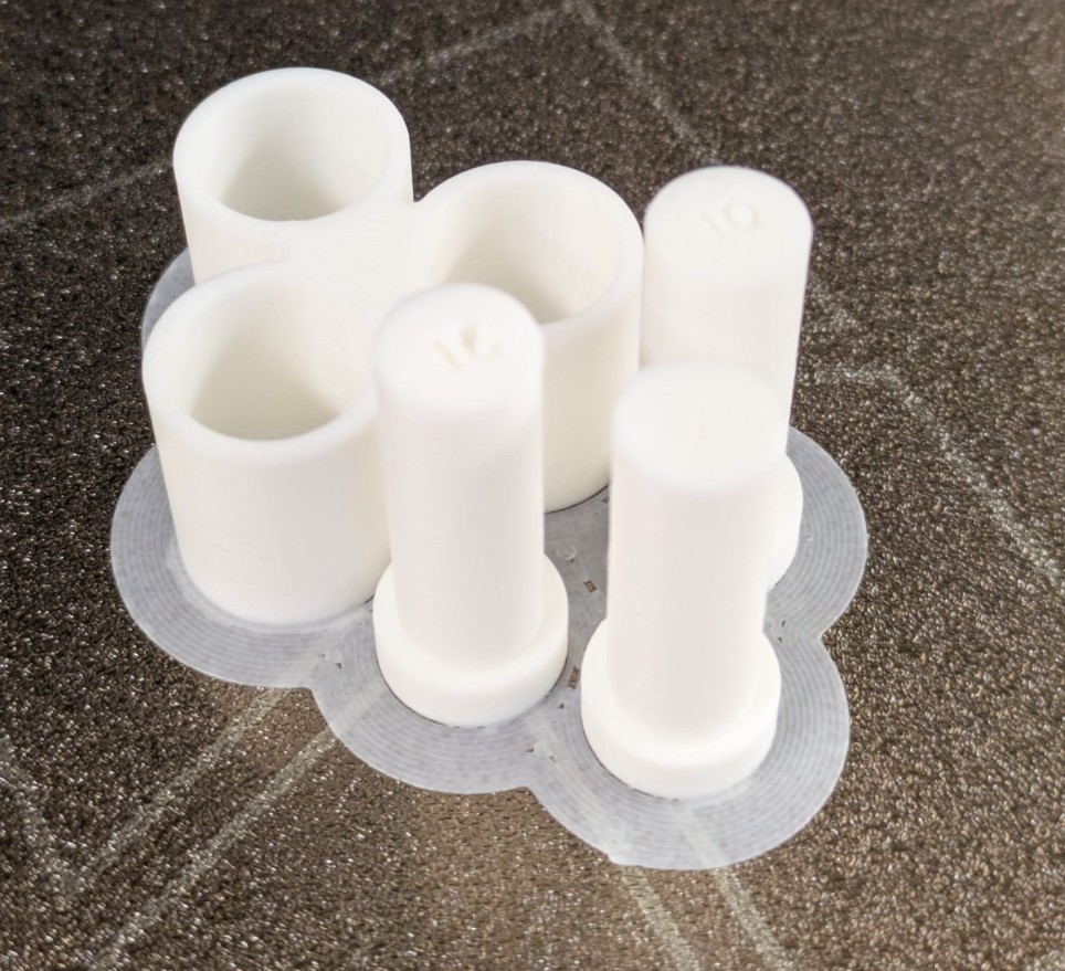
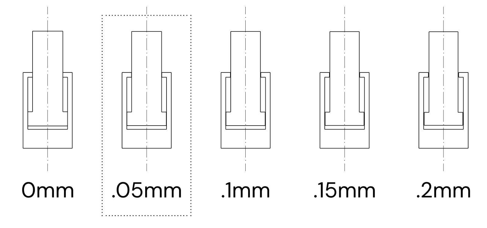
The above shows the different iteratoins I tried before reaching the optimum solution for the printer. Just to reiterate for myself, or anyone reading this: .05mm on both sides gives just enough space to slide without wobble!
Glowmorph 3D Printed Prototype Assembly
Primary Assembly Idea. I wanted to print the entire assembly in as few parts as possible without having support fiklling in parts of the print that need to be clear so that my tolerances can be as consistent as possible. Ultimately I concieved of a two-part base structure that has a cylindrical locking mechanism and radiating pistons that would friction fit into the base.
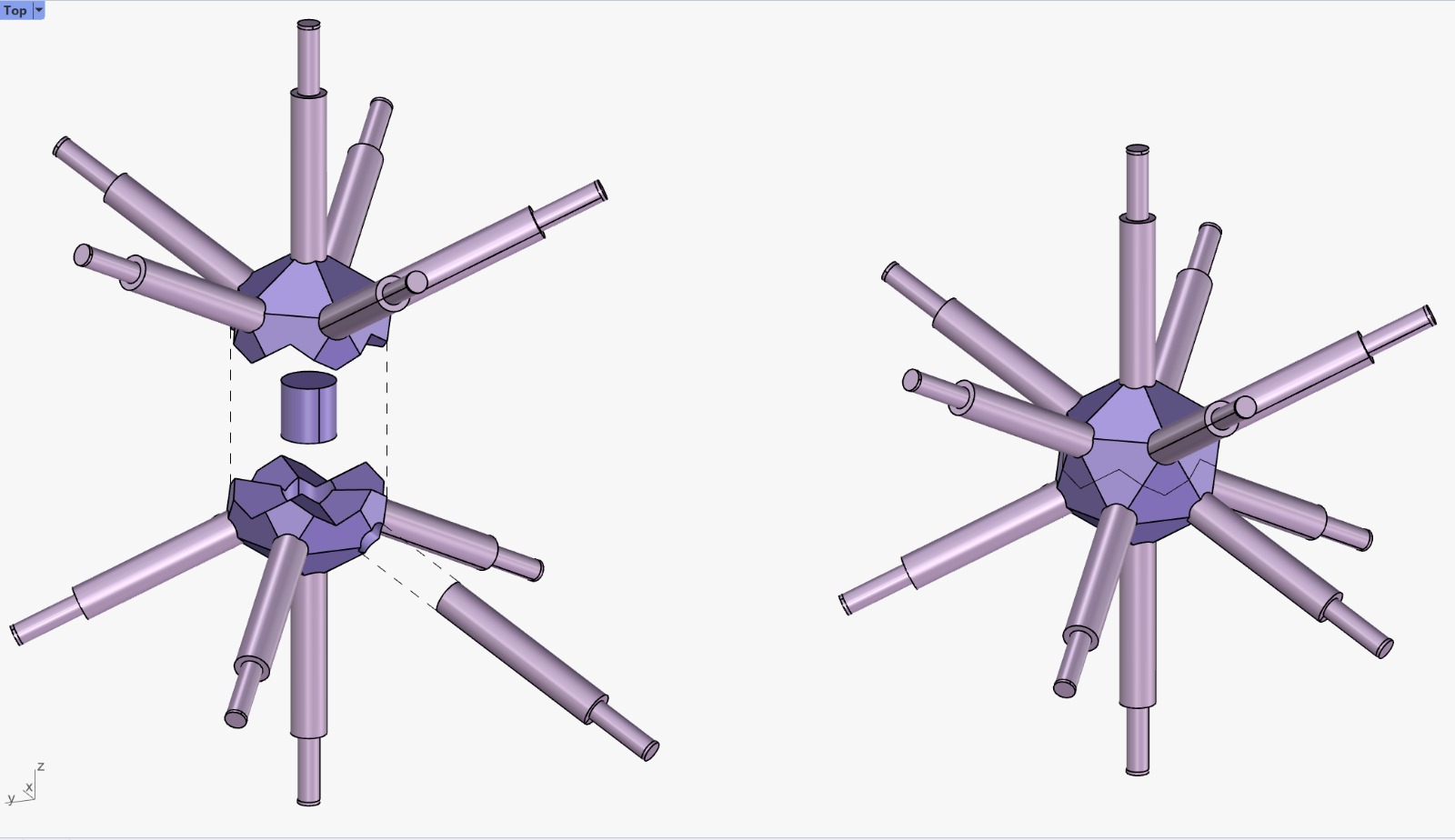
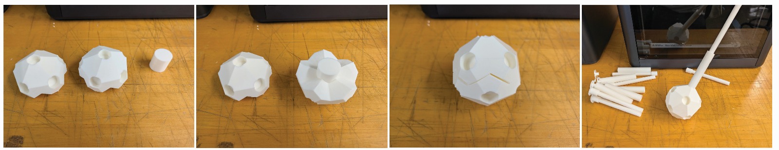
After assembling the two halves and putting them together, I noticed that the Icosohedron base structure did not quite fit. I think that the corner tolerances would have to be adjusted to not be sharp, but rather filleted corners. For sake of time, I attempted to reprint the base Icosohedron as a single block.
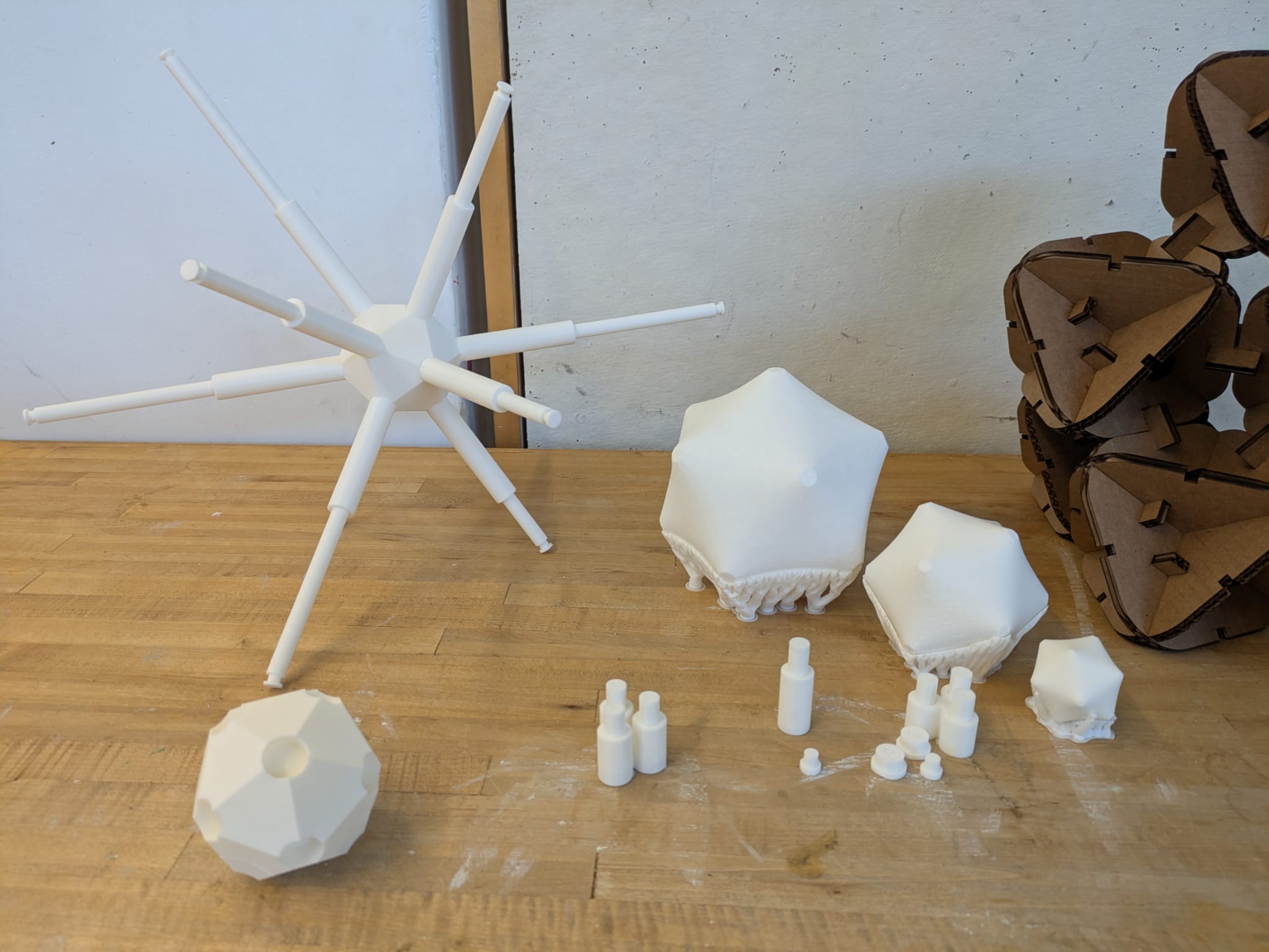
Alternative Assembly Idea. I was inspired by taking the dual polyhedron construction of the icosohedron and creating a dodecahedron sub-grid. This would let me print 12x tiles face up that would not require any support, and would print the cylinders in a favorable location as they would be perpendicular to the print bed. Ultimately, I ran out of time and did not test this assembly method out.
Takeaways / Reflections
- 3D printing requires iterative testing: every printer behaves slightly differently.
- Orientation, support, and bed adhesion are crucial for success.
- Material properties, tolerances, and overhangs directly influence print outcomes.
- Scanners have strengths (opaque objects, general shape) and limitations (transparent, highly detailed interiors).
- Post-processing in software (Rhino, MeshLab) is often necessary to clean scans for practical use.
- Understanding machine and software limits informs design choices early in the process.
- Experimentation teaches more than theoretical reading — hands-on adjustments are critical.
- Combining scanning and printing enables rapid prototyping cycles, helping visualize and refine ideas efficiently.
Shout Outs
- Gert for being such a legendary TA for this week. He offered to show us how to use the printer right after class that allowed us to push ahead with the group assignment, thereby ensuring everyone could have more meaningful time on their own work.
Files from this Week