Week 5 - Electronics Design and EDA
Lab Overview & Equipment
Group Assignment: Observe the operation of an embedded microcontroller using lab equipment.
Lab Equipment
- Oscilloscope: Measures voltage over time; visualizes live signals, noise, and code execution.
- Power Supply / Power Meter: Provides stable voltage; linear = clean, switching = common. Adjust voltage safely to control functions.
- Multimeter: First debugging tool; checks resistance (continuity), voltage, and identifies shorts. Many have a sound mode for quick tests.
Safety
- Electricity is powerful — like a fire hose.
- Up to ~20V can be safe, but caution is key.
- Work typically at 3.3V–5V.
- Confirm all connections before powering devices.
Applications in Code
- Control stepper motors.
- Test timing and microcontroller responses.
- Correlate oscilloscope signals with code execution for debugging.
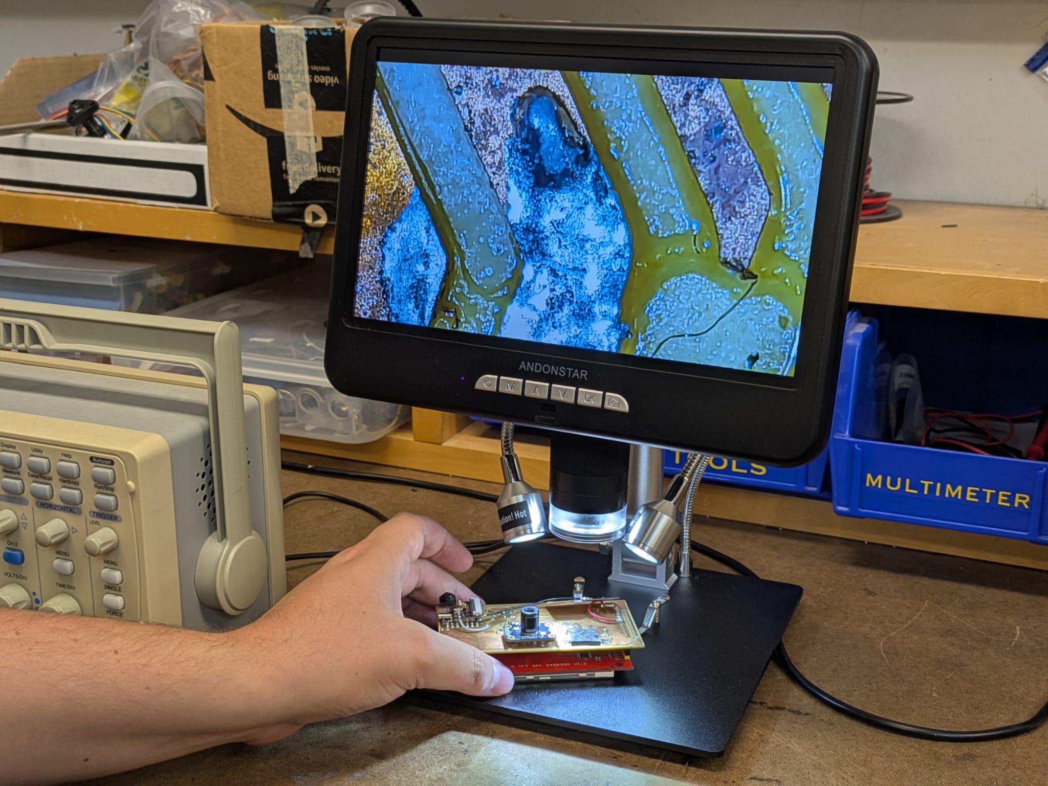
Gert showing us how to use the digital magnification device.
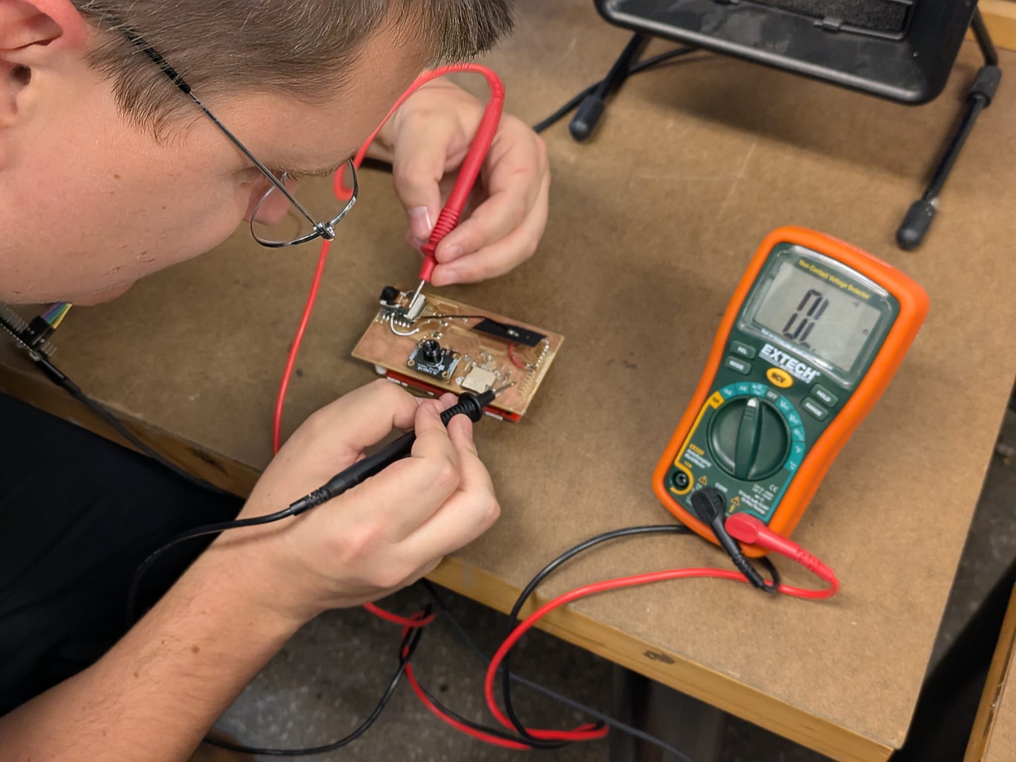
Gert walking us through the multimeter.
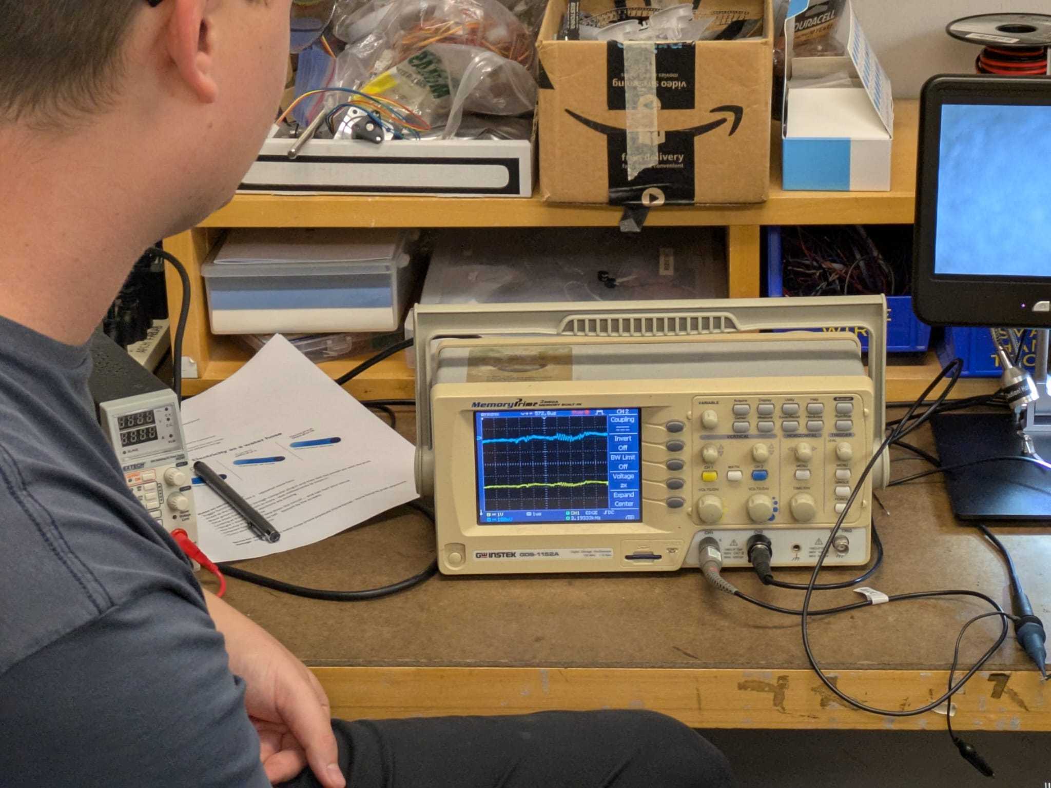
Gert demonstrating the Oscilloscope.
Oscilloscope Signal Behavior: Stepped vs Continuous
Oscilloscopes can display signals in two main ways: continuous (smooth) or stepped (sample-and-hold). This behavior depends on both the nature of the signal and the scope's sampling method.
Continuous (Analog) Display
- The scope traces voltage in real time, showing smooth transitions.
- Best for analog signals or slowly changing waveforms.
- Classic analog scopes display this naturally; modern digital scopes emulate it with very high sample rates.
Stepped / Sample-and-Hold (Digital) Display
- The scope samples the voltage at discrete time intervals and holds each value until the next sample.
- This can create a “stepped” appearance if the sampling rate is too low compared to the signal speed.
- Common for modern digital scopes and digital signals (logic lines).
When it Matters
- Digital data pins: Step displays often work well because the signal changes abruptly (0 → 3.3V/5V), and timing edges are most important.
- Analog or PWM pins: Smooth, continuous variations require higher sampling rates; otherwise the waveform may appear jagged or stepped.
- Rule of thumb: The faster the signal relative to the sampling rate, the more “stepped” it will look.
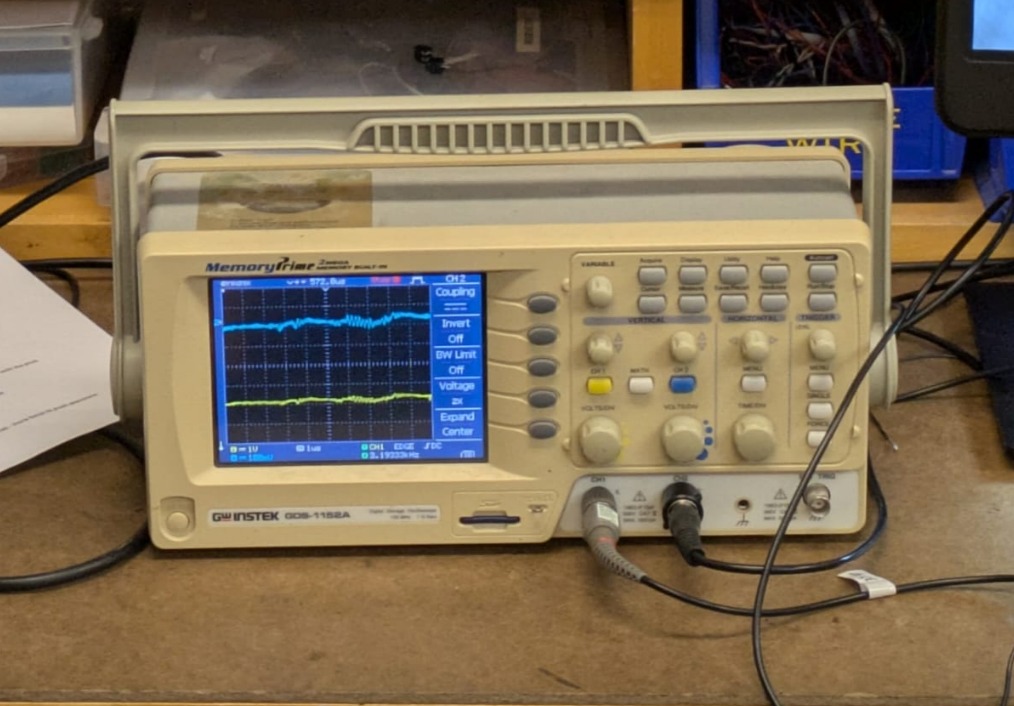
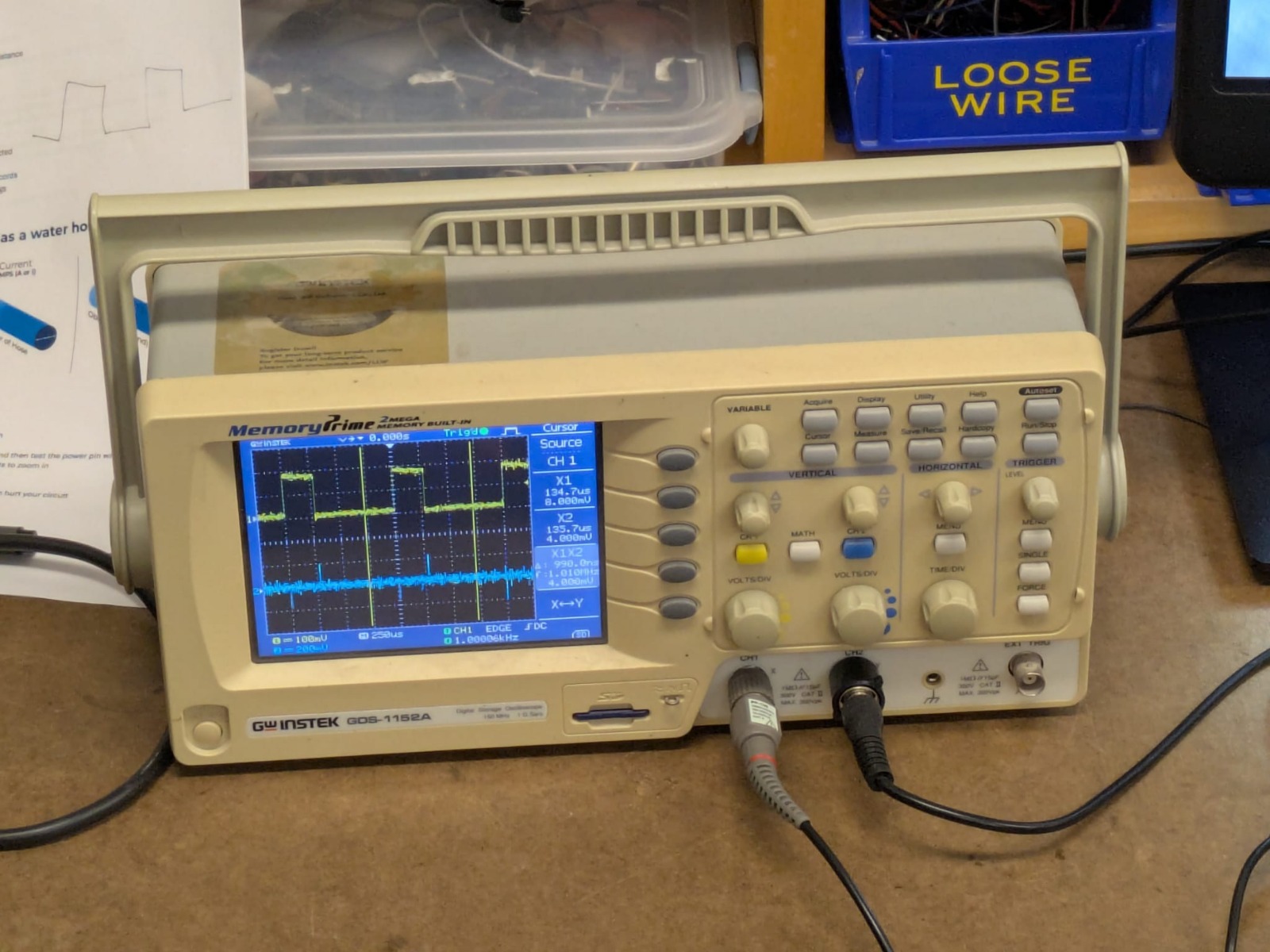
Side-by-side comparison. Top is an analog pin. Bottom is a data pin transmitting 'hello work' in binary at a specified frequency.
KiCad Recitation - EDA Exercise
Libraries & Components
- Add libraries via GitHub using the shared QR code.
-
Verify pin numbers: actual pin is 26; don’t trust
aliases like
D. - Reference the schematic if confused; Seeed Studio schematics are open source.
- Resistors: use 1206 size for this class.
Connections & Nets
- Net: a logical connection between components.
- Wire: the physical manifestation of a net.
- For milling, use 0.4 mm thick wire.
Board Setup in KiCad
- Set minimum clearance (0.4 mm) via the board setup icon (gear).
- Minimum track width: 0.4 mm
- Minimum annular width: 0.1 mm
- Edit track widths under predefined sizes (0.4 mm, 0.8 mm, etc.).
-
Place components using net labels (e.g.,
PIN_RESISTOR). - Adjust grid size; implicit convention = 100 mils.
-
Shortcuts:
U– select entire wire,R– rotate component - Use Edge.Cut layer to define board outline.
Design Rule Check (DRC)
- Checks logical rules and geometric constraints.
- Ensures no violations before fabrication.
Plotting & Exporting
- Export format: Gerber
- Output directory:
gerber - Double-check included layers before plotting.
- Hit Plot to generate all necessary files.
Ordering a Fabricated Board
- Use PCBWay for instant quotes.
- Upload Gerber files (zip format).
- Delivery: ~1–1.5 weeks.
Making Your Own Board
- Convert Gerber files to image using Gerber2Img (drag & drop).
- Include traces and edge cut; lock dimensions.
- Install and import 3D shapes for visualization.
- Import graphics via:
Import → Graphics → F.Cu.
Starting out in Kicad
So I am not only extremely new to Kicad but to all things electronics and EDA in general. I put together the following notes to give myself a bit of a visual cheat sheet that I could look back on as I move forward with my own custom board design. KiCad has two main editors, each serving a distinct purpose. Breakdown as follows:
1. Schematic Editor (Logical Design)
- Purpose: Draw my circuit connections.
-
Key Actions:
- Add components: Place → Component (resistors, ICs, capacitors, etc.)
- Draw connections: Place → Wire (creates nets)
- Label nets: Place → Net Label (makes nets easier to reference)
- Check for errors: Tools → Electrical Rules Check (ERC)
- Tip: Focus only on what connects to what, not where it goes physically.
2. PCB Layout Editor (aka the Physical Board)
- Purpose: Place components and route the copper traces.
-
Key Actions:
- Import netlist from schematic: Tools → Update PCB from Schematic
- Place components: click and drag footprints on the board
- Route traces: Route → Interactive Router (connect pins physically)
- Set board outline: use Edge.Cut layer
- Check design: Tools → Design Rules Check (DRC)
- Export Gerber files for fabrication: File → Plot
- Tip: Think about spacing, manufacturing rules, and board size.
How They Connect
- The schematic editor defines the electrical logic (nets, pins, connections).
- The PCB editor realizes that logic physically (footprints, traces, board shape).
- Workflow: Schematic → Netlist → PCB → Route → DRC → Gerbers → Fabrication
My First Board Design!
I had no idea where to start. I have a basic grasp of EDA but not sure what would be a good base board to begin testing out motors and sensors, which I know I will need for my final project. So I turned to ChatGPT to help identify a good place to begin. The following is a conversation with it, which is available to read here: Starting my Project with ChatGPT As of now, my final project - Glowmorph - is a kinetic lamp that has 10 or 11 independently moveable arms that retract based on the presence of movement around the lamp. With this in mind, I wanted to create a good base board that I could begin playing with to learn the key principles. I fed into chatgpt the provided inventory we have for the class.
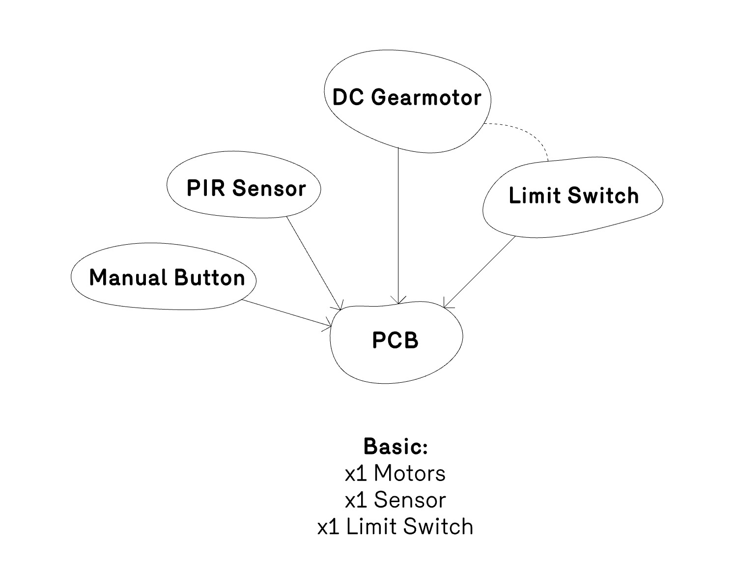
Diagram for my mechatronic system idea.
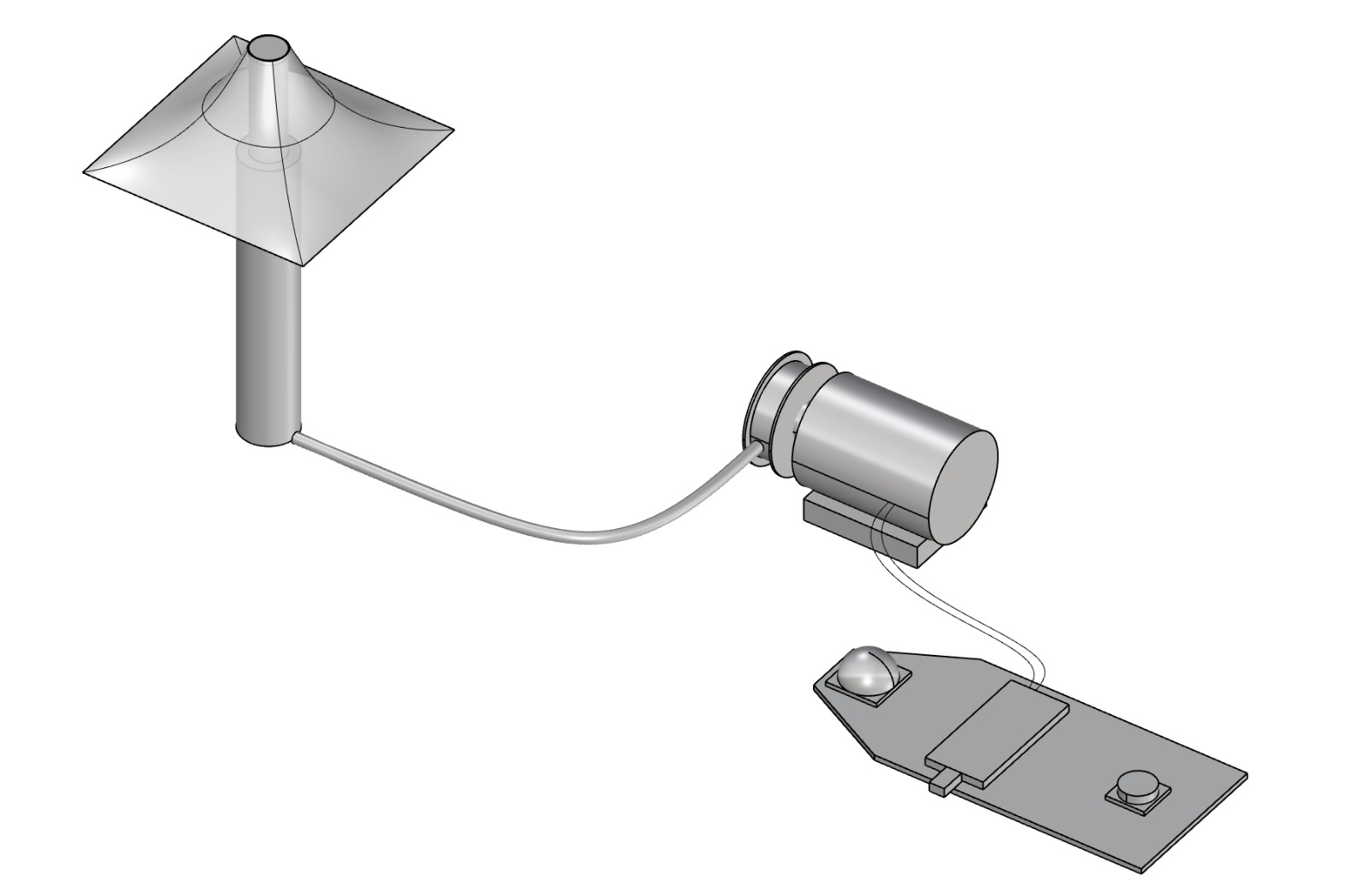
Diagram for parts of my mechatronic system.
Well... a Change of Plans
Initially I wanted to create a beginner board that would speak to a servo motor that could move one arm like I have in my final project and have a PIR sensor that would detect motion. Ultimately I have come to realize there are way too many unkown skills here, so I decided to start really simple, as It's my first board. Sort of a 'Step 0'. I will keep this little mechatronic system for my final project but its too complex to learn the basics of PCB design. Since I am interested in making lighting, and I wanted to make an LED programmable by 3 sliding switches denoting RGB values.
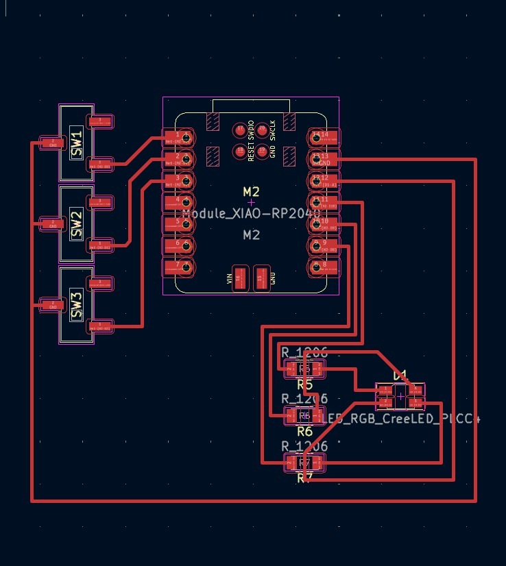
Above is my first layout. I referenced the blinking LED PCB board as a base.
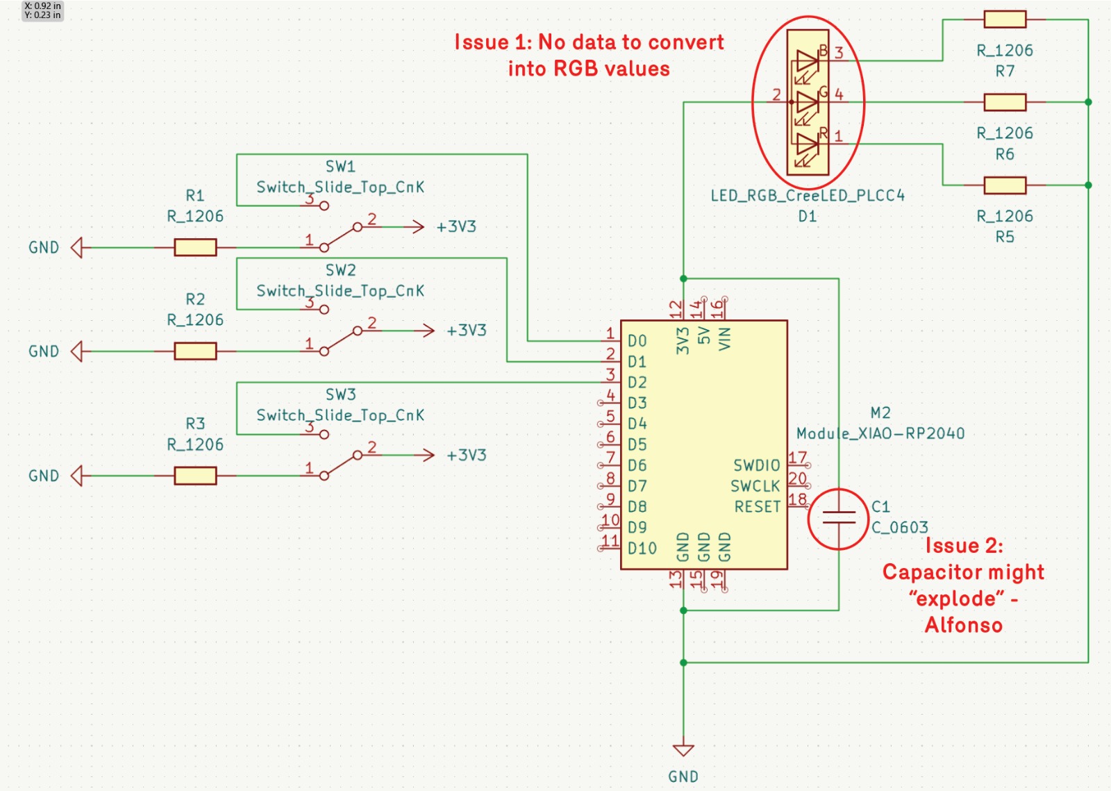
After reviewing it with Alfonso, I was told that there is no value going into the RGB LED to affect color so it wouldnt work. On top of that, my capacitor has the risk of blowing up. Sounds like a bad time!
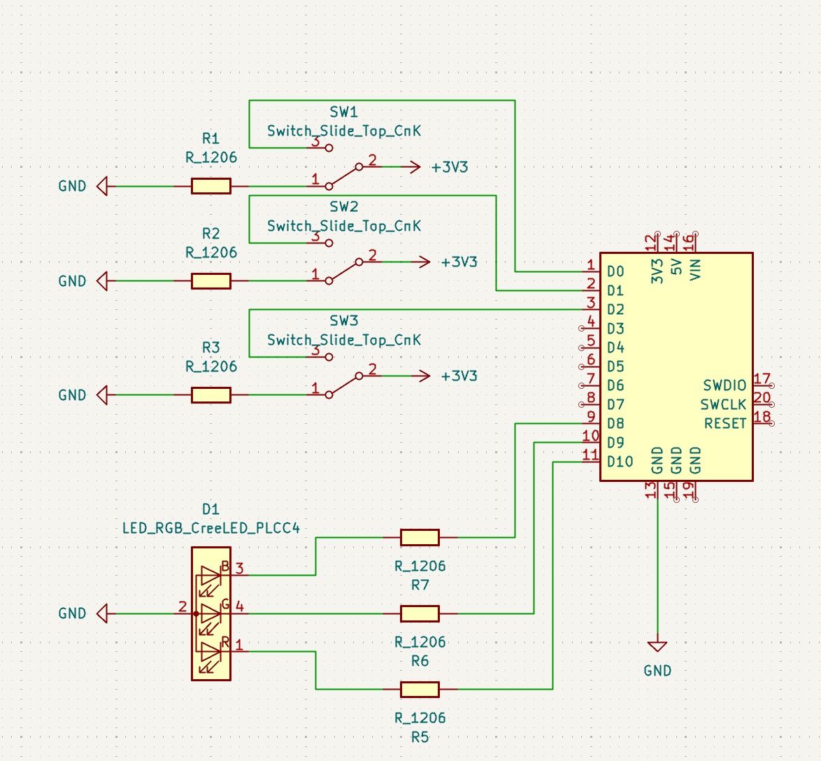
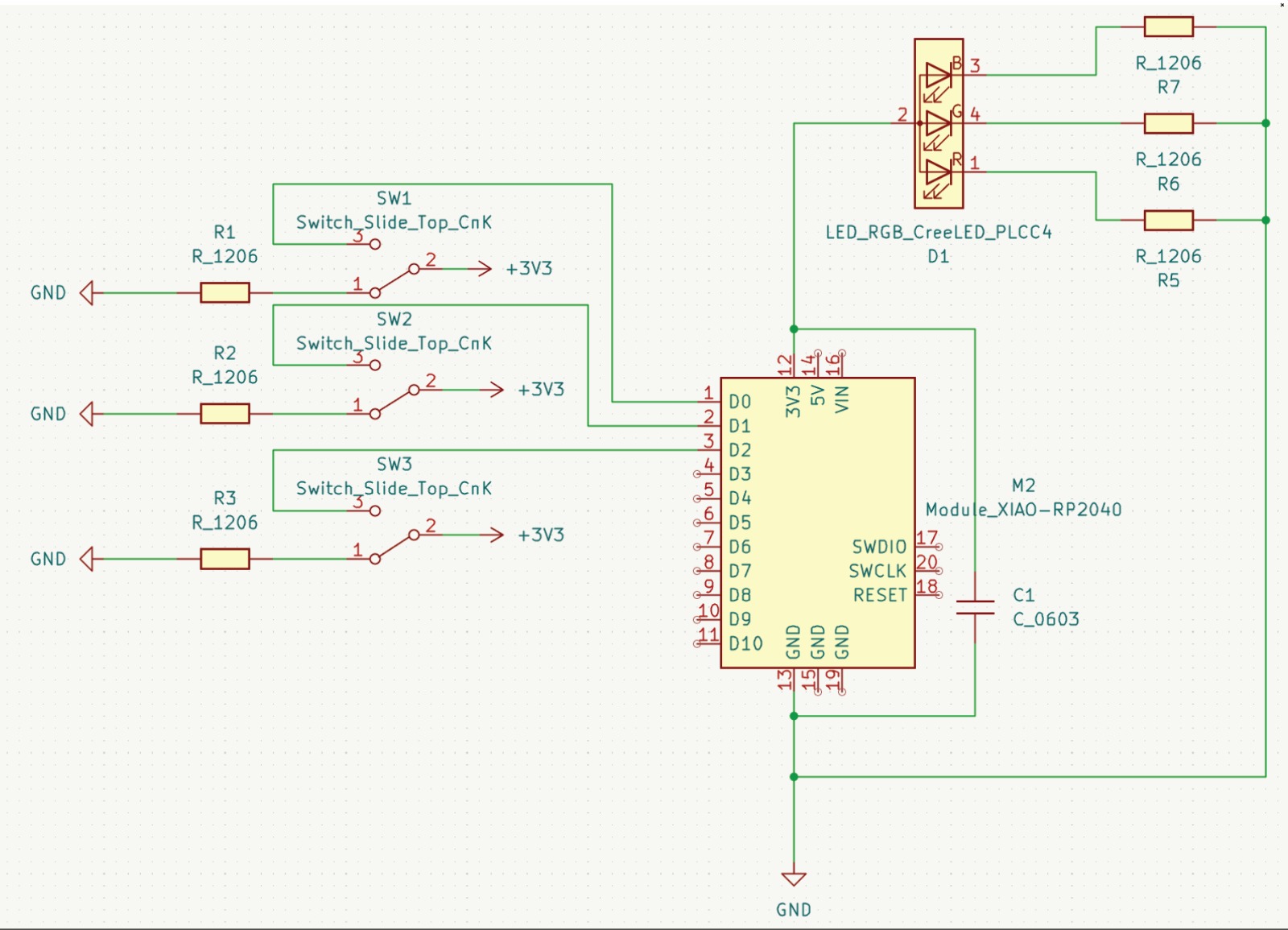
Latest board design here! I like that RGB will be affected by binary rather than a gradient. It sounds interesting for some reason. I think with enough time I will switch over to 3 potentiometers.
How the RGB Board Works
My final design consists of three slide switches, one RGB LED, and the Seeed XIAO RP2040 microcontroller.
Microcontroller (XIAO RP2040)
The XIAO is the brain of the circuit. It provides both power (3.3V) and logic signals to the rest of the board. It interprets the three switch positions as digital inputs (either HIGH or LOW) and outputs the corresponding signals to the red, green, and blue channels of the LED.
Pins D0, D1, and D2 are set as inputs connected to the slide switches, while pins D3, D4, and D5 are outputs driving the RGB LED channels. This should mean the XIAO reads the state of each switch and turns on or off the corresponding color.
Slide Switches (SW2–SW4)
Each switch has two possible positions:
- OFF (open): The microcontroller’s internal pull-up resistor holds the signal at 3.3V, so it reads as HIGH.
- ON (closed): The switch connects directly to GND, bringing the signal down to 0V (LOW).
RGB LED
The RGB LED has four pins: one common cathode (shared ground) and three anodes for red, green, and blue. Each color pin passes through a current-limiting resistor before connecting to the XIAO’s output pins. This ensures the LED doesn’t draw too much current and burn out.
When an output pin goes HIGH, current flows from the pin → through the resistor → through the LED’s internal diode → to GND. The LED channel lights up accordingly. Each of the three LED channels behaves independently, so the board can produce combinations of red, green, and blue light.
Power and Ground
The +3.3V line powers the XIAO directly. All other components share a common ground with the microcontroller. This shared reference point ensures voltage levels are consistent and logic signals are correctly interpreted. No external 3.3V lines are needed for the switches or the LED since all power and logic flow through the XIAO’s pins.
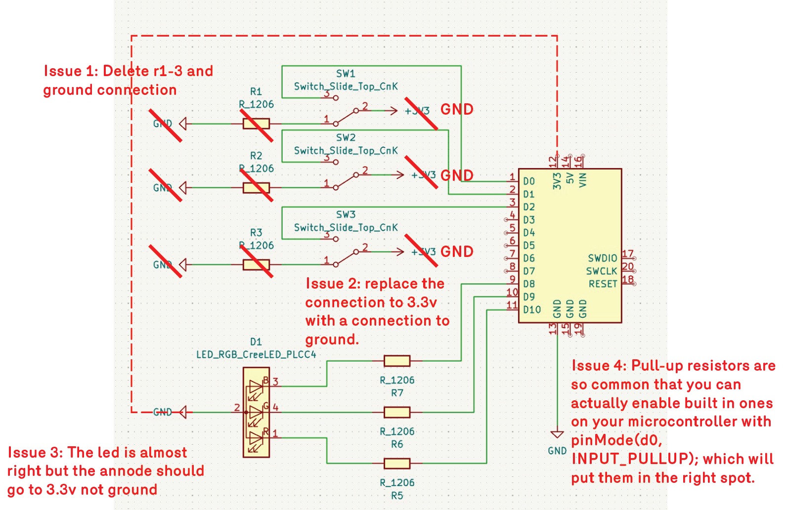
Anthony marked up my board and gave the following advice: "Ok this is close but needs some updates. Your switches aren't quite right. You can totally delete r1-3, and the ground connection then replace the connection to 3.3v with a connection to ground. Pull-up resistors are so common that you can actually enable built in ones on your microcontroller with pinMode(d0, INPUT_PULLUP); which will put them in the right spot. The led is almost right but the annode should go to 3.3v not ground "
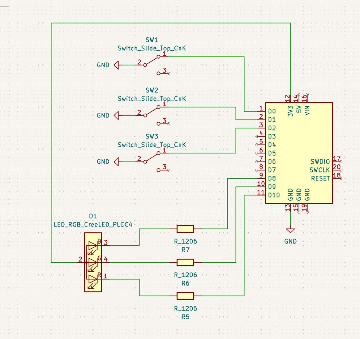
Above is the board updated to match Anthony's specifications. I plan on replacing the slide switches with potentiometers for next week, but I wanted to get to the actual PCB board layout.
First attempt at PCB board design. I'm struggling a bit thorugh the LED RGB pins obviously, but I wanted to give it a simulation first.
Simulation
So for virtual simulation, I was told that Wokwi does not have the XIAO RP 2040. On top of that, I am aware that the software does not have all the components that we have in the fab inventory. So I wanted to test my board through a breadboard first. With the help of Gert, I found an old XIAO RP2040 and pulled it off of the board that it was on, so that I could comandeer it for my test. Unfortunately, I damaged the pins in the process.
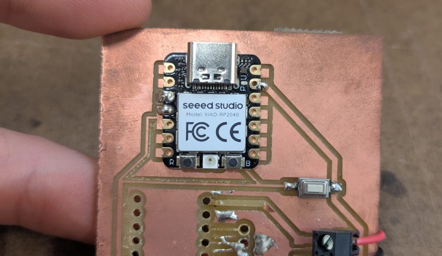
Above is the board I stole.
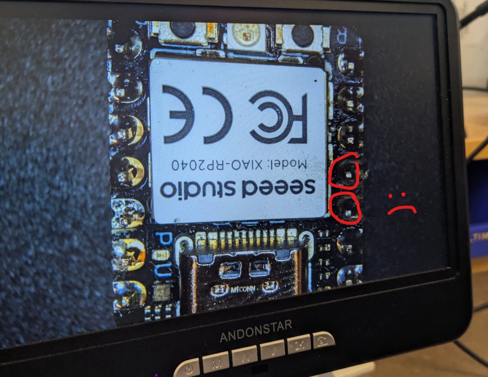
Above I think i ripped out the pins during my grand theft. I wanted to try it anyway! Reduce, reuse, recycle.
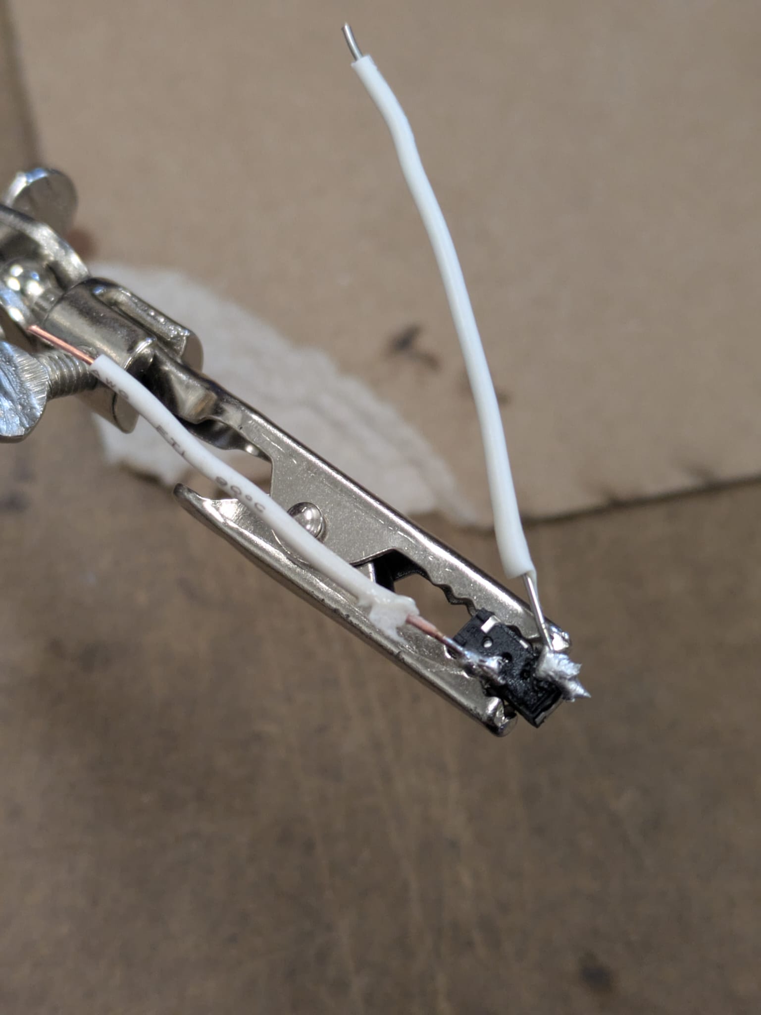
Above is showing how I'm soldering the switches onto cables to use in the breadboard. Not sure if there's a better way to do this.
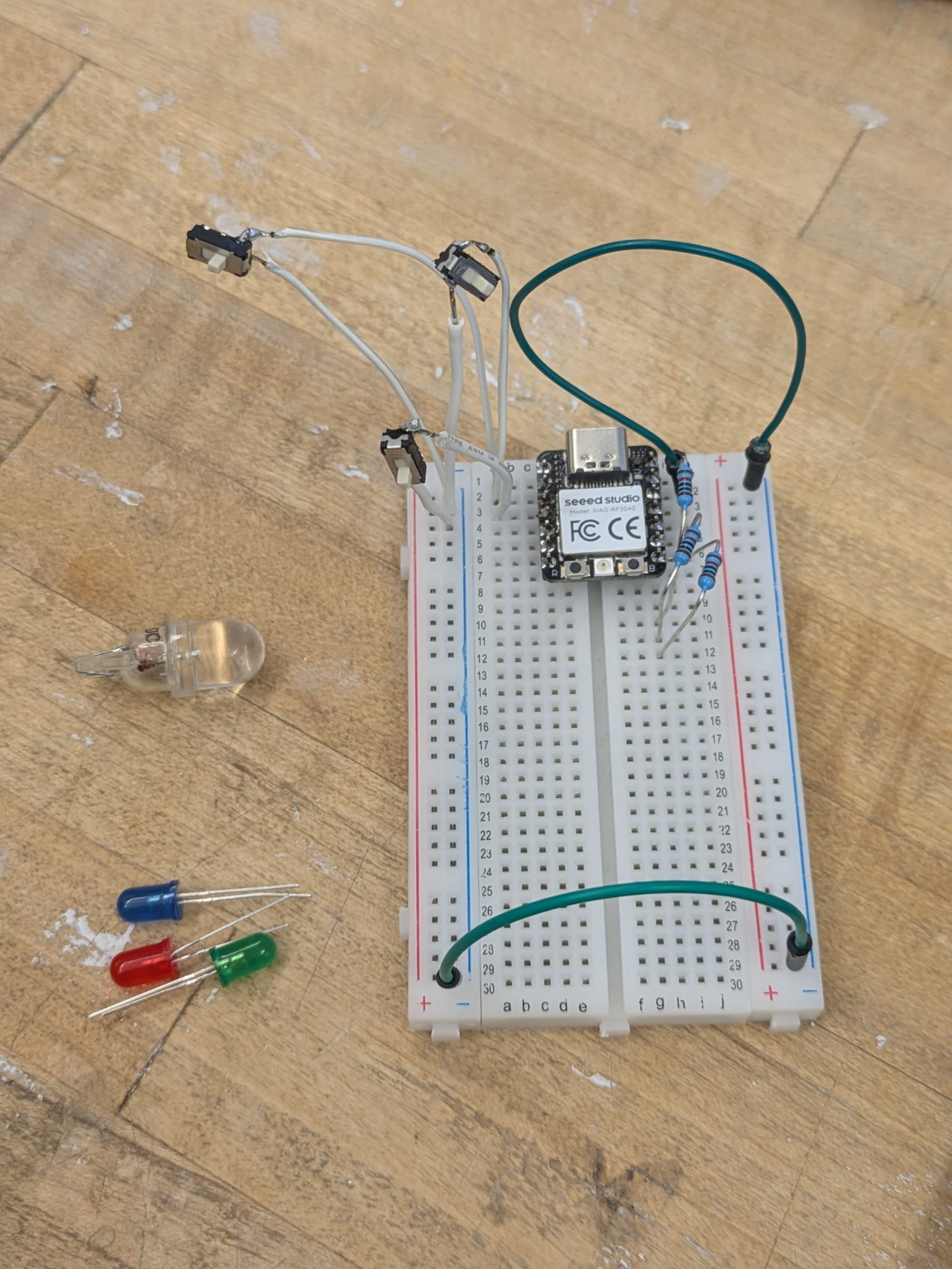
Breadboard time! I followed the above diagram and schematic to get this model up and running. Unfortunately, I could not find the LED that we apparently have in inventory. I was looking for CLV1A-FKB-CK1VW1DE1BB7C3C3 , but can only find separate R, G and B LED as well as an unidentified LED! I will be looting the Mars lab CBA bins, otherwise I need to change my schematic to match our inventory.
Takeaways / Reflections
- Using lab equipment requires careful preparation and safety awareness.
- Understanding the difference between nets and wires is critical in EDA.
- KiCad workflow emphasizes clear board setup: track widths, clearance, and annular rings must be defined before plotting.
-
Shortcuts like
Ufor selecting wires andRfor rotating components greatly speed up layout. - Design Rule Checks (DRC) prevent fabrication errors and help maintain logical consistency.
- Plotting Gerber files and ordering boards from services like PCBWay illustrates the real-world flow from design to physical PCB.
- Hands-on experimentation with voltage, power supply, and oscilloscope measurements deepens understanding of microcontroller behavior.
- Combining code with physical signals allows for debugging and verification of embedded systems in real time.
Shout Outs
- Quentin for the detailed walkthrough that helped clarify KiCad workflows and EDA principles.
- Gert for demonstrating the use of oscilloscopes, power meters, and multimeters — this hands-on guidance made the lab much more approachable and practical. Gert also gave me an introduction to breadboards, and helped me solder for an hour of his valuable time. I am deeply appreciative to him!
- Alfonso killed it as well, I greatly appreciate his time reviewing my schematic PCB layout. Thank you!