Week 8 – Input Devices
Week’s Objective
This week’s goal was to explore different types of sensors and learn how to integrate them into a simple circuit. I wanted to test a few inputs that could eventually drive my final project — a lamp that can grow and shrink based on its environment. My focus this week was understanding the behavior of analog input and how it can control light output.
Notes on Inputs and Communication
Analog vs Digital
- Analog signals vary continuously between 0 V – 3.3 V. Examples: potentiometers, light sensors. On the XIAO RP2040, pins A0–A3 can read analog values.
- Digital signals are binary — HIGH (1) or LOW (0). Examples: buttons, switches, LEDs. On the XIAO, pins D0–D9 are digital.
UART – Universal Asynchronous Receiver / Transmitter
- Serial communication using TX (transmit) and RX (receive).
- Commonly used to send data between microcontrollers or a PC.
- “Asynchronous” means no shared clock — both ends agree on a baud rate.
- Example: XIAO → Arduino IDE → Serial Monitor.
I²C – Inter-Integrated Circuit
- Two-wire bus: SDA (data) + SCL (clock).
- Multiple devices share the same two wires, each with a unique address.
- Ideal for small sensors and displays.
- Example: XIAO reads a temperature sensor and an OLED screen on one bus.
SPI – Serial Peripheral Interface
- Four wires: MOSI, MISO, SCK, CS (Master Out/In, Clock, Chip Select).
- Faster than I²C but requires one CS line per slave device.
- Used for fast peripherals like displays or SD cards.
MicroPython
- A Python interpreter for microcontrollers – not a protocol.
- Lets you write Python scripts directly on the XIAO RP2040.
- Supports UART, I²C, SPI, PWM and GPIO operations.
Mini Development Board
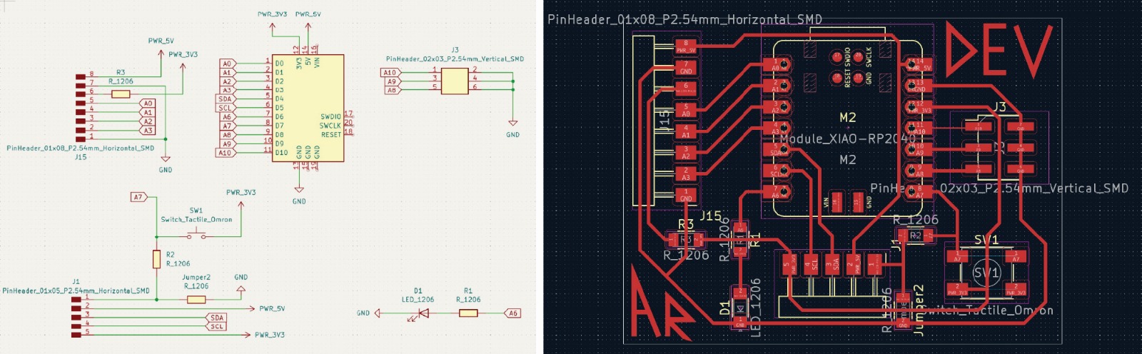
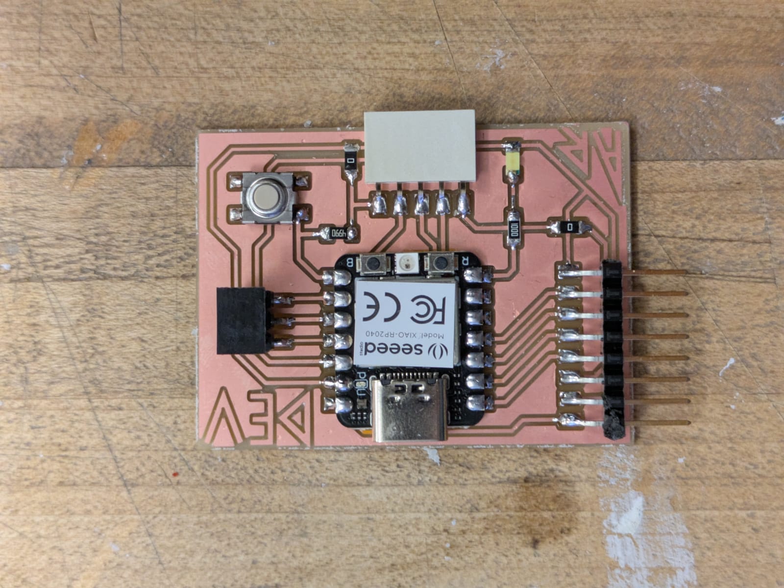
I designed a small breakout / development board to make connecting sensors simpler. Rather than soldering each input circuit individually, this board acts as a flexible testbed. It was inspired by Adrián Torres’ Fab-XIAO board, which provides a clean structure for experimenting with multiple inputs.

Seeed Studio XIAO RP2040
The Seeed Studio XIAO RP2040 is a compact board based on the Raspberry Pi RP2040 dual-core processor. It’s fast, reliable, and ideal for modular experimentation.
- Processor: Dual-core ARM Cortex-M0+ @ 133 MHz
- Memory: 264 KB SRAM + 2 MB flash
- Power: 3.3 V logic, USB-C powered
- Interfaces: I²C, SPI, UART, 11 PWM pins, 4 ADC pins
- Extras: Onboard reset button and USB bootloader for easy programming
All GPIOs run at 3.3 V logic. The 5 V pin comes directly from USB power and shouldn’t be used as input to any signal pins.
Development Board Layout and Notes
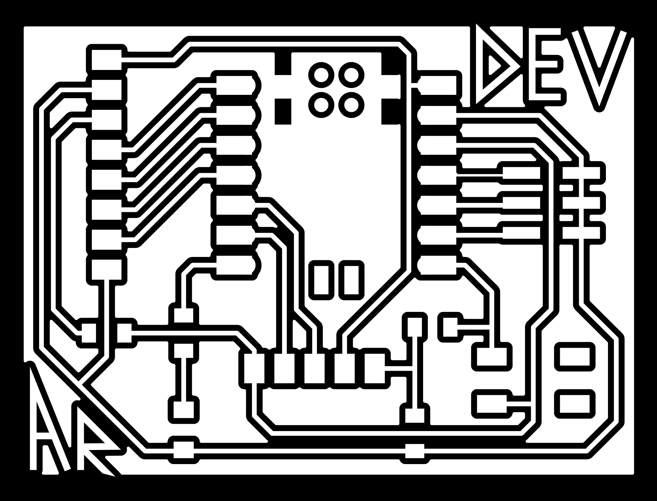
My board follows the same structure as Torres’ Fab-XIAO design but is tuned for my own workflow. I kept the XIAO footprint and pin orientation but modified power rails and headers for faster prototyping.
- Power rails: 3.3 V and GND along both edges.
- Sensor headers: A0–A3 and I²C lines with VCC + GND.
- Actuator headers: PWM outputs with dedicated GNDs.
- Debug section: On-board LED and button for testing.
- I/O labels: All pins match the XIAO pinout.

Phototransistor Test
I tested a simple analog input using a PT15-21B/TR8 phototransistor. Its collector connects to 3.3 V through a 10 kΩ resistor and the emitter goes to GND. The junction between them feeds A0. An LED on D6 changes brightness based on ambient light in the room. This experiment demonstrated the analog responsiveness of the XIAO and how easily light intensity can modulate a PWM signal.
// Auto-balanced phototransistor LED controller (XIAO RP2040)
// D0: Sensor input (10k pull-up to 3.3V)
// D6: LED output (PWM)

const int sensorPin = D0;
const int ledPin = D6;
const int ADC_MAX = 1023;
int minVal = 1023;
int maxVal = 0;

void setup() {
  pinMode(ledPin, OUTPUT);
  Serial.begin(9600);
}

void loop() {
  int sensorValue = analogRead(sensorPin);
  if (sensorValue < minVal) minVal = sensorValue;
  if (sensorValue > maxVal) maxVal = sensorValue;

  int range = max(maxVal - minVal, 10);
  int brightness = map(sensorValue, minVal, maxVal, 0, 255);
  brightness = constrain(brightness, 0, 255);

  float boosted = pow(brightness / 255.0, 1.8);
  int output = int(boosted * 255);

  analogWrite(ledPin, output);

  Serial.print("Sensor=");
  Serial.print(sensorValue);
  Serial.print("\t Brightness=");
  Serial.println(output);
  delay(100);
}
The exponential mapping gave more dramatic light transitions — in darker environments the LED fades almost completely off, then brightens quickly as light increases. This gave a good foundation for linking sensor values to visible output on the same board.
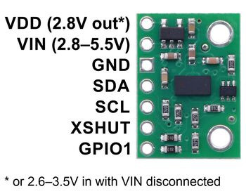
Time of Flight Sensor (VL53L1X)
The Time-of-Flight sensor measures distance by emitting infrared pulses and calculating the time they take to reflect back. I wired the VL53L1X to my XIAO using I²C (SDA → D4, SCL → D5, plus 3.3 V and GND). This compact module can measure from a few millimeters to about two meters and became the basis for my lamp’s proximity response.
I first ran it on the development board using Adafruit’s VL53L1X library and watched live distance values over serial. The next step was to tie those readings to an LED so changes in distance could be seen immediately.
LED Brightness Controlled by Distance
I mapped the measured distance to PWM brightness on D6 — the closer an object is, the brighter the LED glows. This simple translation of spatial data into light feedback made the sensor behavior tangible and will later drive motion in the final lamp.
// VL53L1X distance → LED brightness (XIAO RP2040) #include#include Adafruit_VL53L1X tof = Adafruit_VL53L1X(); const int ledPin = D6; void setup() { Serial.begin(115200); Wire.begin(); pinMode(ledPin, OUTPUT); if (!tof.begin()) { Serial.println("Sensor not found!"); while (1); } tof.startRanging(); } void loop() { int distance = tof.read(); if (distance > 0) { int brightness = map(distance, 30, 300, 255, 0); // closer = brighter brightness = constrain(brightness, 0, 255); analogWrite(ledPin, brightness); } delay(50); }
Custom PCB with OLED
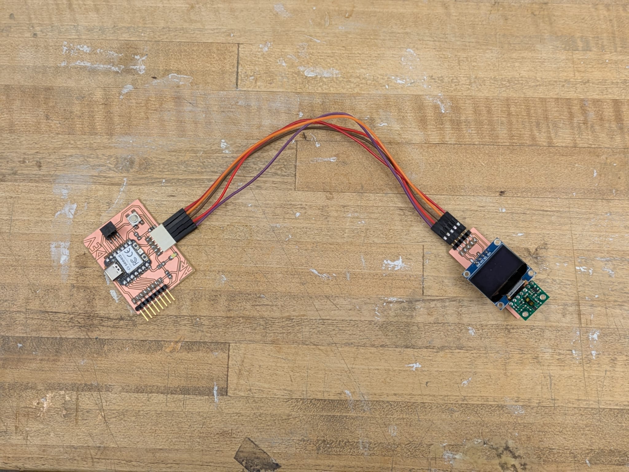
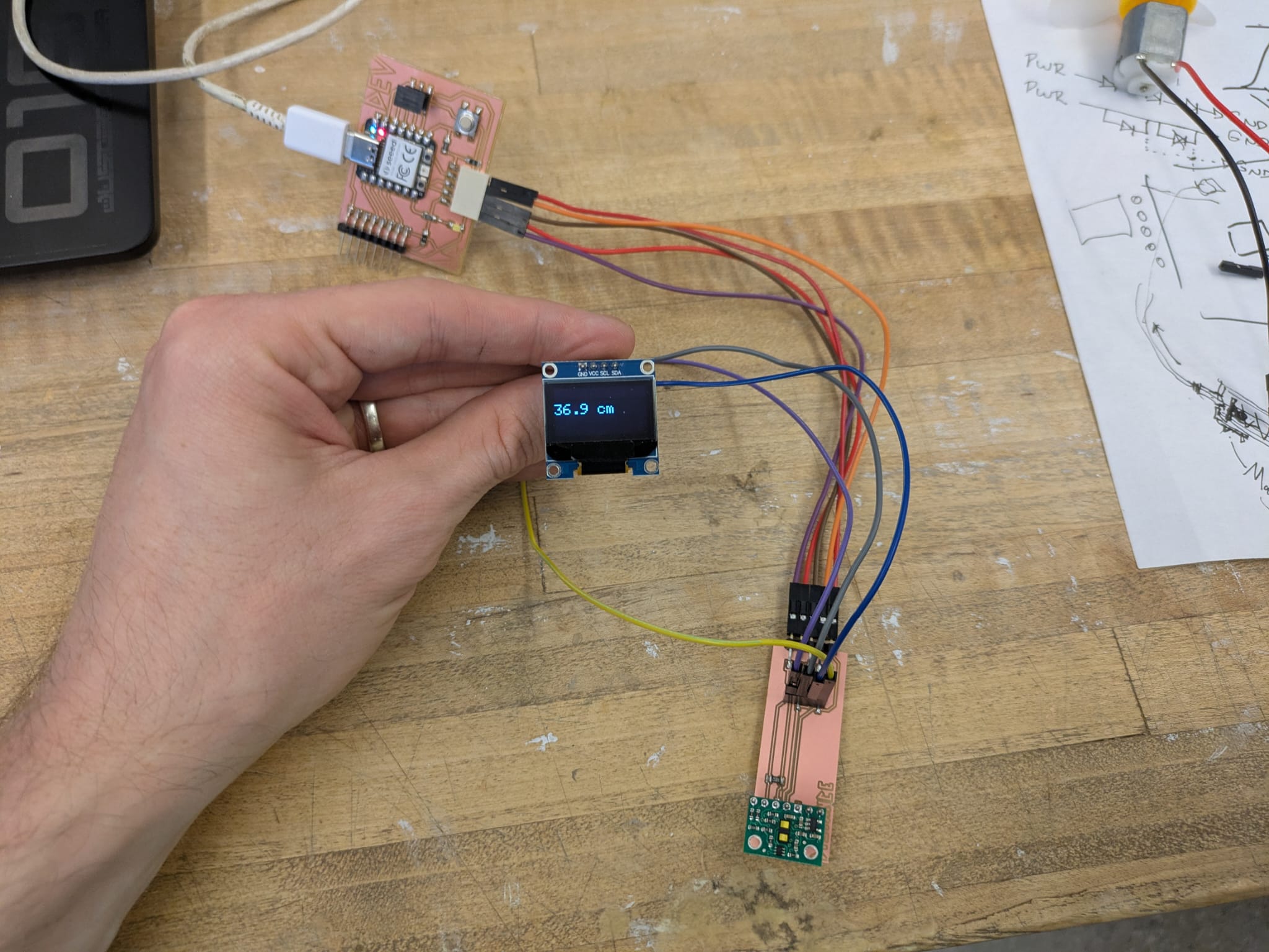
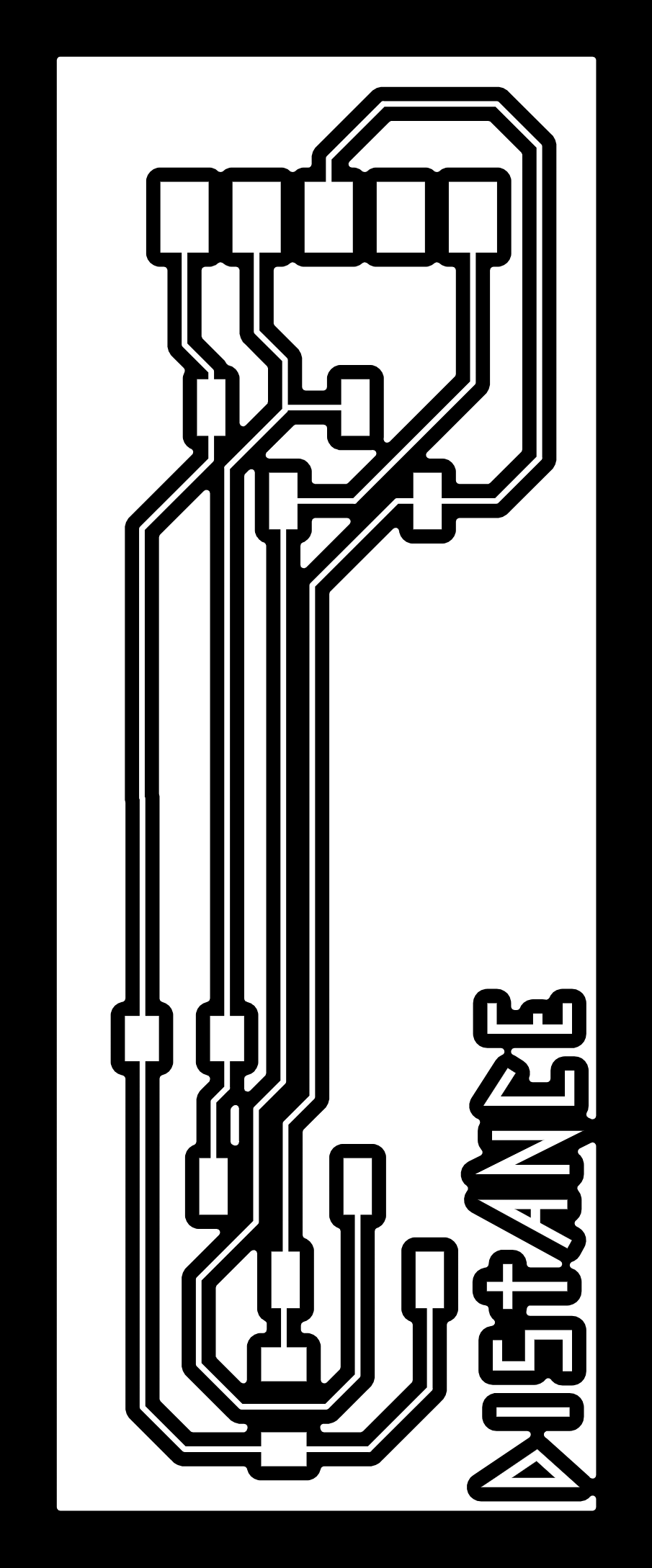
Finally I made a dedicated board combining the VL53L1X, a small I²C OLED, and indicator LEDs. The OLED displays live distance data without needing serial output. It’s mounted slightly behind the sensor plane (about 5–8 mm) to avoid blocking the ToF field of view. I reserved around a 32×32 mm footprint for the display on the PCB. Everything runs on 3.3 V through the same I²C bus. The resulting board acts as a compact diagnostic module — the sensor reads distance, the OLED shows it, and the LED visually echoes proximity in real time. Big shoutout to TA Gert on sharing his code with me, which allowed me to finish on time!
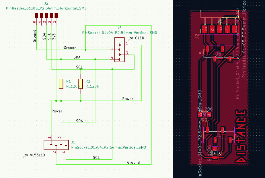
I was pursuing a breakout board situation. I know these components aren't cheap, and I hate wasting things, so I wanted everything to plug and play. This does require longer to sit through schematics, however. Unfortunately I switched power and ground on my OLED. Fortunately i caught the mistake before powering anything on, I would have hated to damage my components! The correction is indicated and fixed below:

#include#include #include #include // OLED display dimensions #define SCREEN_WIDTH 128 #define SCREEN_HEIGHT 64 #define OLED_RESET -1 // Not used // Create instances Adafruit_VL53L1X vl53 = Adafruit_VL53L1X(); Adafruit_SSD1306 display(SCREEN_WIDTH, SCREEN_HEIGHT, &Wire, OLED_RESET); void setup() { Serial.begin(115200); Wire.begin(); Serial.println("Initializing Distance Board..."); // Initialize VL53L1X sensor if (!vl53.begin(0x29, &Wire)) { Serial.print(F("Error initializing VL53L1X sensor. Status: ")); Serial.println(vl53.vl_status); while (1) delay(10); } Serial.println("VL53L1X sensor OK!"); // Start ranging if (!vl53.startRanging()) { Serial.print(F("Couldn't start ranging. Status: ")); Serial.println(vl53.vl_status); while (1) delay(10); } vl53.setTimingBudget(50); // faster measurement cycle (ms) // Initialize OLED display if (!display.begin(SSD1306_SWITCHCAPVCC, 0x3C)) { Serial.println(F("SSD1306 allocation failed")); while (1) delay(10); } display.clearDisplay(); display.setTextSize(1); display.setTextColor(SSD1306_WHITE); display.setCursor(0, 0); display.println("Distance Sensor Ready"); display.display(); delay(1000); display.clearDisplay(); } void loop() { // Get distance in millimeters int16_t measure = vl53.distance(); display.clearDisplay(); display.setTextSize(2); display.setTextColor(SSD1306_WHITE); display.setCursor(0, 20); if (measure > 0) { // Convert to centimeters for display float distance_cm = measure / 10.0; // Print to serial Serial.print("Distance: "); Serial.print(distance_cm); Serial.println(" cm"); // Print to OLED display.print(distance_cm, 1); display.println(" cm"); // Add a little "OK" status text display.setTextSize(1); display.setCursor(0, 50); display.println("Range OK"); } else { Serial.println("Measurement error"); display.setTextSize(2); display.setCursor(0, 20); display.println("---"); display.setTextSize(1); display.setCursor(0, 50); display.println("Out of Range"); } display.display(); delay(250); // Refresh rate }

Takeaways / Reflections
This week tied together several ideas about how sensors translate environmental data into behavior. Working with the Time-of-Flight sensor helped me understand how hardware and software can communicate continuously, while testing the phototransistor made the feedback loop between analog input and PWM output tangible. The spectrometer demo was a reminder that lab tools demand both care and calibration — precision is as much about patience as it is about code.
I also realized how documentation is a kind of design process. Adrian Torres’s records were more than references; they became a form of mentorship. Translating his workflow to my own helped me structure how I approached wiring, testing, and debugging. Seeing each input visualized — whether as light, distance, or data on screen — turned abstract code into something physical and immediate.
More broadly, this week was about learning how to slow down, measure, and understand signal behavior before trying to make things move or react. Everything became an exercise in tuning — light, distance, and perception.
Shout Outs
- Gert — for being incredibly generous with his time, walking me through how to use the spectrometer, and explaining calibration and measurement techniques. His hands-on approach made the lab setup feel accessible and less intimidating.
- Adrián Torres — for his detailed documentation from Fab Academy, which helped me figure out where to start with my own development board and input device workflow.