Week 9 - Output Devices
Identifying Design Criteria in Glowmorph
I wanted to use this week to understand which motors would be best for my final project, Glowmorph. The kinetic lamp is essentially a puppet, where all the motors are hidden in the base plate, and cables are routed through to actuate its arms. This is done to save space in the lamp and keep it lightweight, with no bulky inner node.

This week I aimed to get one of these arms working. Not an unreasonable goal, but we’ll see.

My proposed construction sequence for a single kinetic arm. Much still to refine, but the overall logic is there.
Locking Down Control Architecture
System Snapshot - 1/11 Piston Arms
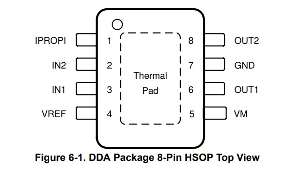
- Actuator: NEMA‑17 stepper + DRV8248 step/dir driver
- Sensing: VL53L1X ToF at the arm tip
- Homing: 1× endstop — microswitch or tiny Hall sensor + magnet at “retracted”
- Control: RP2040 handling step/dir + I²C
- I²C fan‑out for 11 ToFs: either wire each VL53L1X XSHUT to its own GPIO and set unique addresses at boot, or use a TCA9548A I²C multiplexer
- Power: 24 V for steppers, separate 5 V for logic/ToF
Building Upside Down

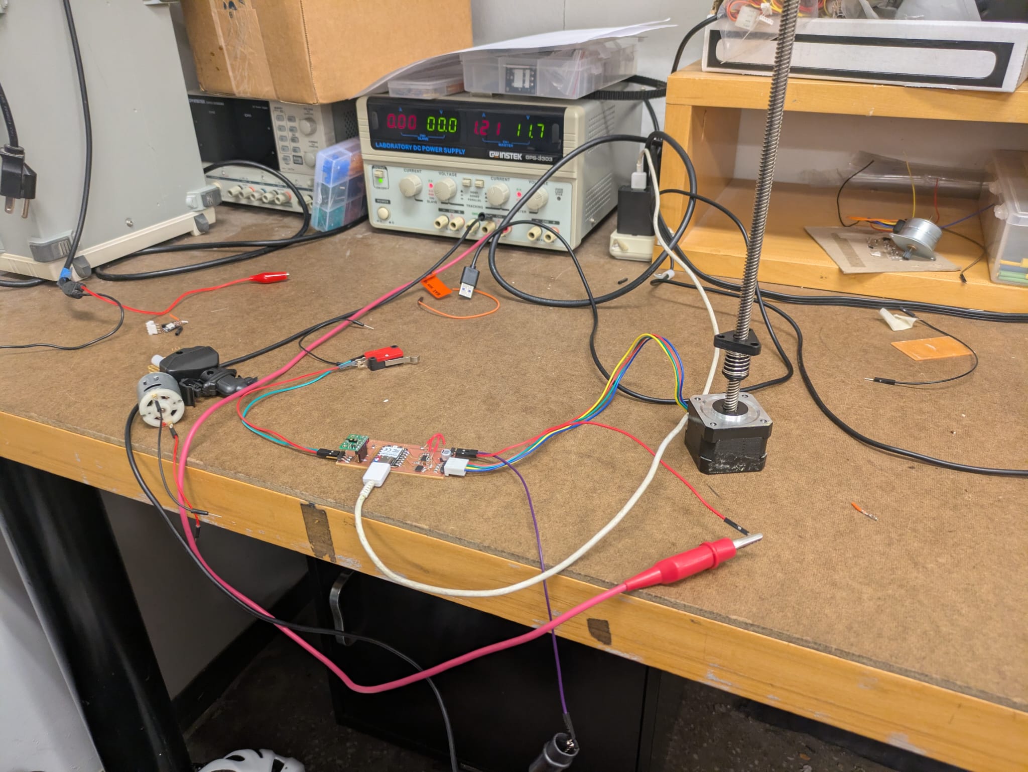
I built a test arm upside down so gravity could assist retraction:
- Natural return force — gravity replaces the extension spring
- Torque verification — see if the motor can lift the piston assembly
- Friction and damping test — study telescoping smoothness under load
- Safer failure mode — gravity drops the arm gently if power is lost
The NEMA 17 stepper is a 4‑wire bipolar motor rated for 12 V and typically 0.4–1.2 A/phase depending on model. It provides smooth 1.8° (200‑step/rev) motion and strong torque — ideal for Glowmorph’s initial motion testing.
Because it’s a bipolar motor, it must be driven by an H‑bridge driver such as DRV8428, A4988, or DRV8825 (not ULN2003).
Typical wire pairing:
• Coil A → Red + Blue (A+, A–)
• Coil B → Green + Black (B+, B–)
Verify with a multimeter — each coil should read ~1–3 Ω.
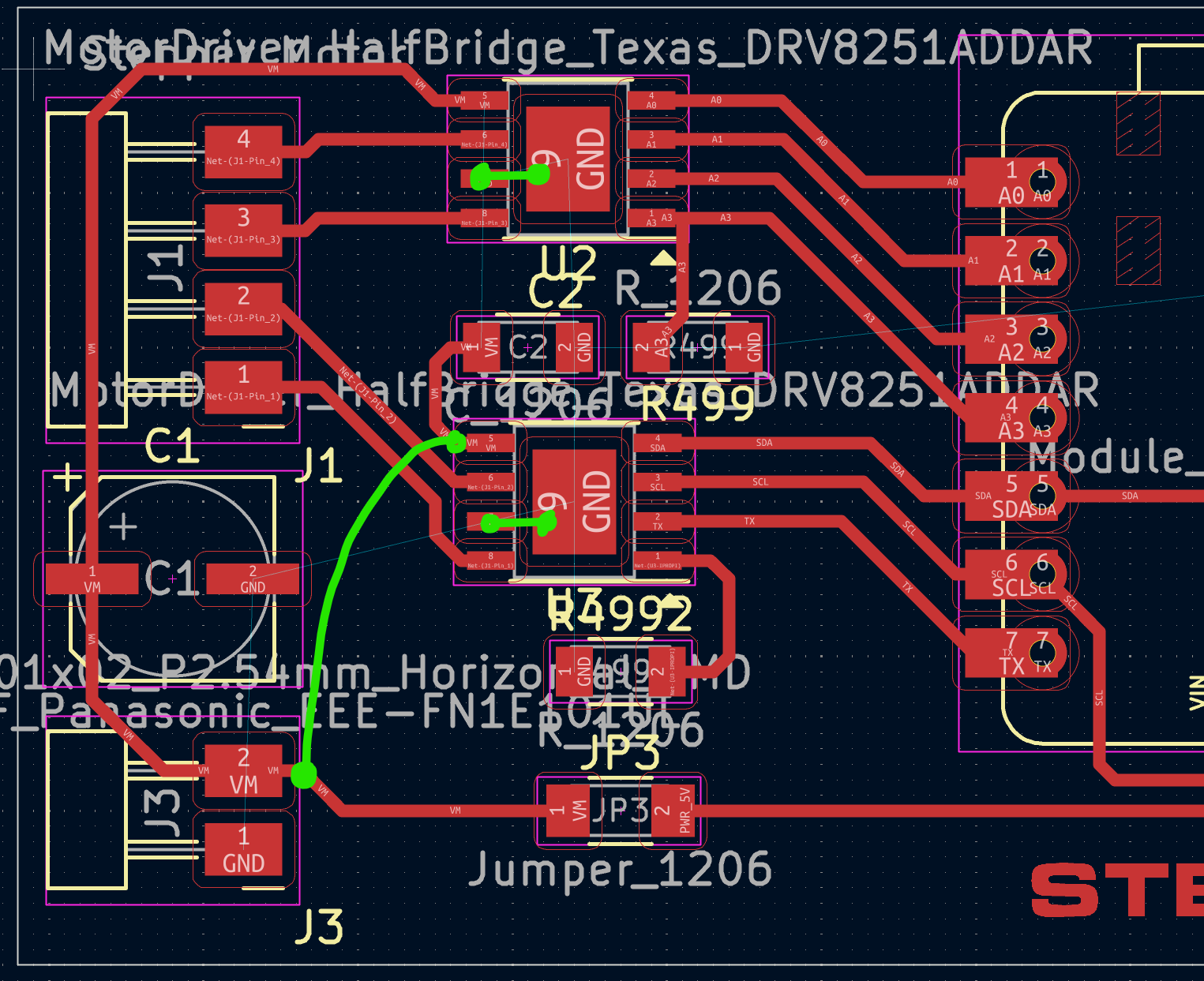
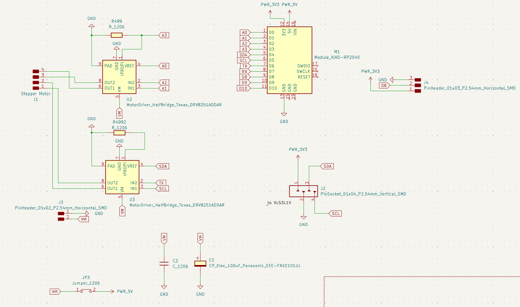
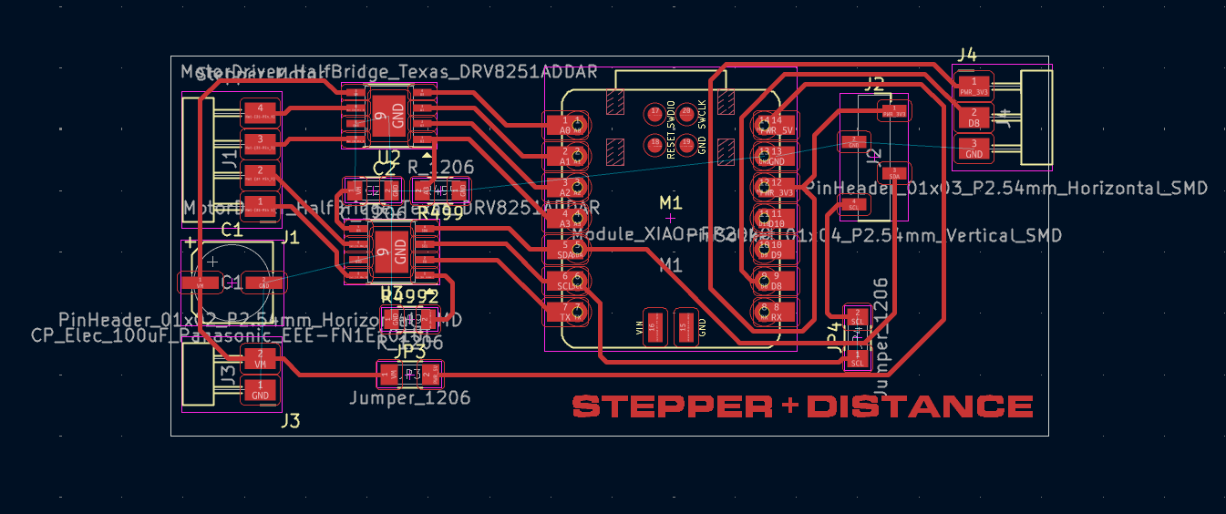
For this circuit, I used a Texas Instruments DRV8251A.
Being new to motor drivers, I started by replicating Neil’s schematic and PCB, then adapting his code from the class site.
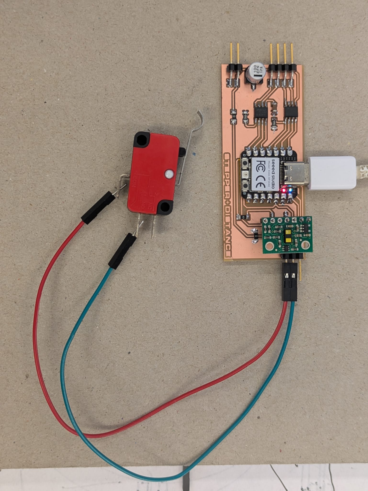
Testing Peripheral Components
Before testing the motor, I verified the Time‑of‑Flight sensor and limit switch. The terminal displayed distance readings and switch states as expected.
#include#include #include #define STEPS_PER_REV 48 // Jameco 7.5° stepper #define IN1 A0 #define IN2 A1 #define IN3 A2 #define IN4 A3 #define LIMIT_PIN D8 // limit switch signal pin Stepper stepper(STEPS_PER_REV, IN1, IN3, IN2, IN4); VL53L1X vl; int dir = 1; // 1 = forward, -1 = reverse void setup() { Serial.begin(115200); Wire.begin(); pinMode(LIMIT_PIN, INPUT_PULLUP); // internal pull-up vl.setTimeout(500); if (!vl.init()) { Serial.println("Failed to detect VL53L1X!"); while (1); } vl.startContinuous(50); // start continuous readings every 50 ms stepper.setSpeed(10); // initial RPM Serial.println("Stepper + VL53L1X + Limit ready"); } void loop() { int distance = vl.read(); // Pololu library function if (distance > 0) { Serial.print("Distance (mm): "); Serial.println(distance); // Adjust motor speed based on distance int speed = map(distance, 50, 400, 5, 60); speed = constrain(speed, 5, 100); stepper.setSpeed(speed); } // Check limit switch if (digitalRead(LIMIT_PIN) == LOW) { Serial.println("Limit hit! Reversing direction."); dir *= -1; // reverse direction delay(300); // debounce delay } // Move motor continuously stepper.step(dir); }
Troubleshooting the Stepper Driver Board
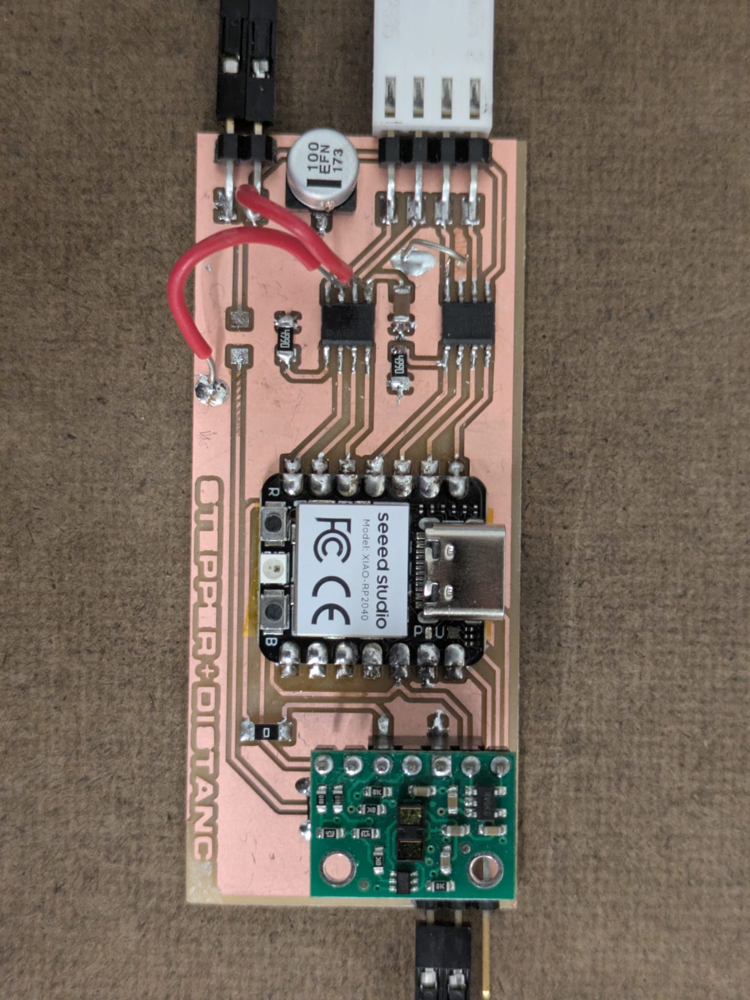
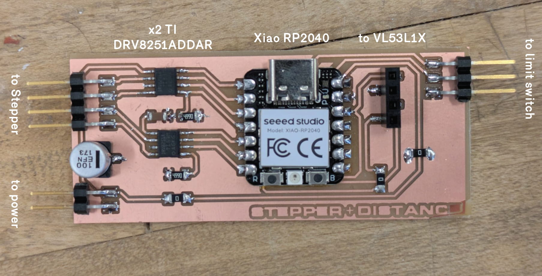
The motor didn’t turn — just a faint hum and a whiff of “motor smell.” This led to a long debugging session. After fabricating my own dual H‑bridge board based on Neil’s DRV8251A design, the first tests failed completely. Below is a record of what I discovered.
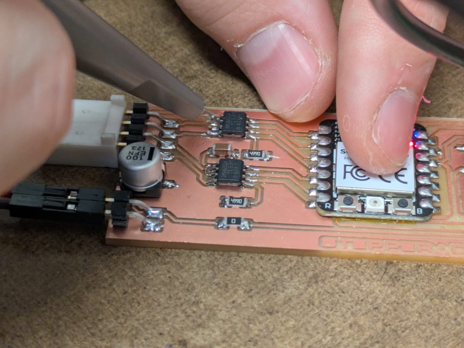
Testing electrical signals using the oscilloscope.
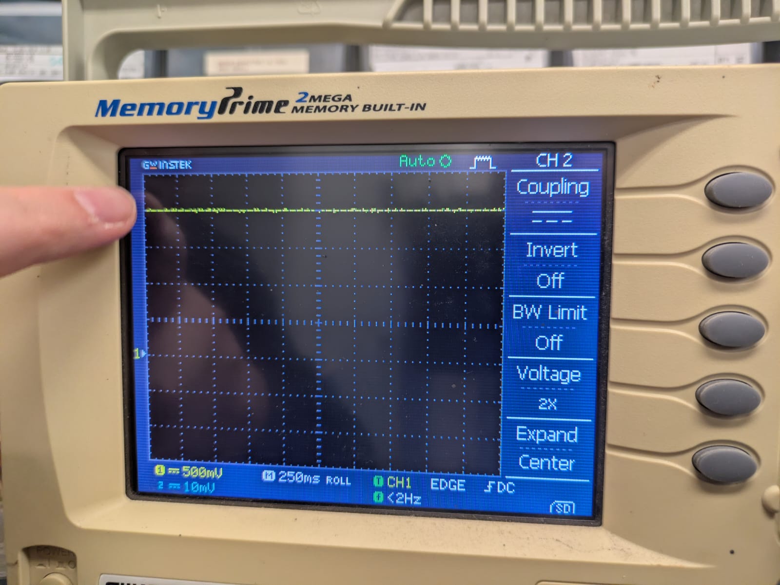
Bench supply confirmed stable voltage across VM and GND.
Signals reached the upper H‑bridge inputs but not the lower one — a key clue.
1. Initial Setup
I copied Neil’s schematic and code, connecting two DRV8251ADDAR half‑bridges to my RP2040. The top driver (U2) showed signals; the bottom (U3) was silent.
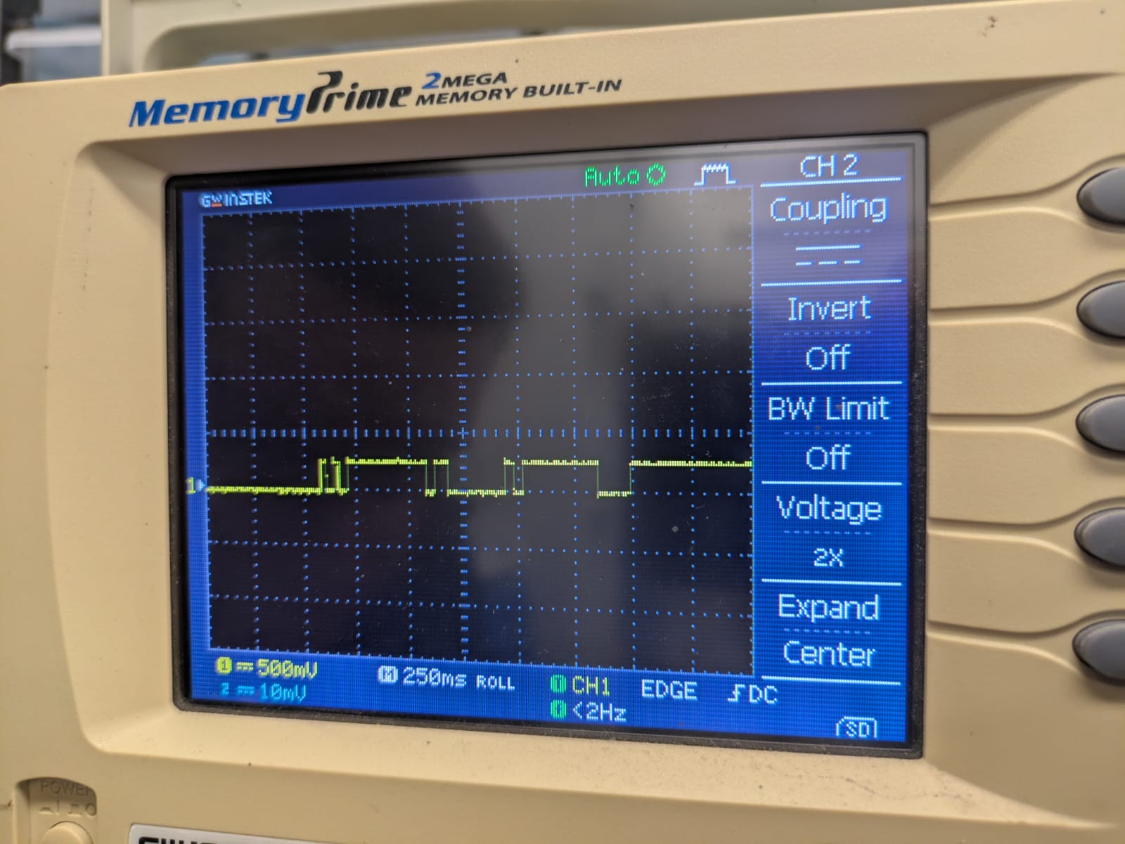
2. Pin Verification
I confirmed IN1 → SCL (D5) and IN2 → TX (D6) matched Neil’s defines. Still, VB (PWM input) had no signal.
3. Tracing VB
A continuity test showed VB never actually reached Xiao D4. I patched the trace with a jumper, and PWM appeared at both VA and VB.
4. Power Checks
U3’s power pin was floating low — the driver stayed asleep. I added 10 kΩ pull‑ups to 3.3 V for both nSLEEP pins. With VM ≈ 9 V and logic = 3.3 V, I still got only faint motion.
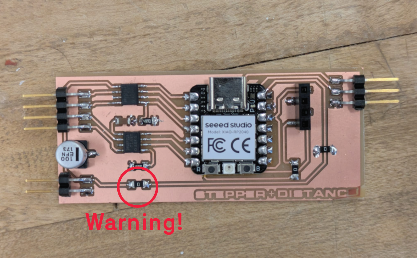
5. VM Connection Mistake
The major oversight: I connected VM to the board’s 5 V rail. Neil’s original board isolates VM with a 0 Ω link; keeping it tied to USB 5 V caused feedback spikes and likely fried the Xiao. After removing the 0 Ω link and powering VM separately (9–12 V), things stabilized.
6. Component Reflow and Verification
Reflowing both DRV8251As — especially VREF, IN1/IN2, and nSLEEP — restored functionality. IPROPI outputs each route through 499 Ω to GND for current sensing. A new RP2040 confirmed PWM stability on both channels.
7. Lessons Learned
- Always isolate VM from USB 5 V.
- Verify continuity at the chip legs, not just headers.
- Ensure nSLEEP is pulled high on both bridges.
- Confirm PWM‑capable pins — D4 can behave inconsistently on the Xiao.
- Scope VA/VB at the driver before connecting the motor to avoid shorts.
Some lessons are learned the hard way — connecting VM and USB 5 V taught me that quickly.
After a brief session with Anthony, he walked me through the faulty connections between VM, the motors and the H-Bridges. Namely, The lower one. First, There was no connection between the ground pin and the ground of the board. I forgot to trace this underneath the footprint of the H-Bridge. Second, there was no power being supplied to the lower H-Bridge. A bit janky, but using insulated wires allowed the code to run with my existing board, rather than create a new one!