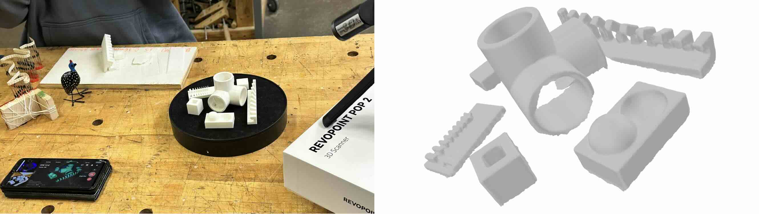
In this exercise, we used the Revopoint Pop 2, which comes with a turntable that helps ensure stable 360-degree scans. The scanner itself is portable, and users need to download the Revo Scan app to connect. Unfortunately, none of the iPhone users in our group were able to connect to the scanner - even after joining the Revo Wi-Fi network and adjusting settings (we will revisit this issue later). Thankfully, our TA and beloved Android user, Gert, was able to get us started with his phone.
We scanned a cluster of small objects found in the lab, mainly some initial test prints from our Architecture peers and an HDPE pipe fitting, to see how much detail the scanner could capture. From the exported .obj file, we noticed that the lower edge conditions of the objects remained jagged, despite the camera capturing over 100 frames. A large factor was definitely the placement of certain objects that obstructed part of the camera's view.
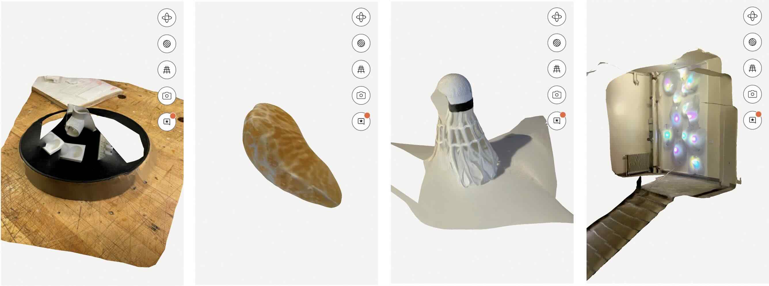
Separately, I used the LiDAR scanner and photogrammetry platform on the Polycam app to try out different objects and spaces in varying intricacies. Although the free version of this had limitations, it was easy to use as a point-and-shooot scanner. I scanned the same objects from the earlier Revpoint test with 94 frames captured and it turned out very poorly (I assume partially due to the messy background and human error from my unstable camera angles).
Additional subjects scanned were a peeled orange (28 frames captured) and badminton shuttlecock (30 frames captured), and a stairwell with an art installation (70 frames captured). So far, I don't have a particular use for 3D scanning in my personal work but I see its value in spatial planning, blueprint creation, VR projects, and digital catalog.
PRINTING
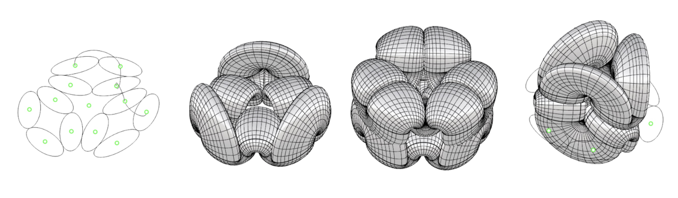
For this exercise, I decided to do a form finding exercise with a simple geometric pattern. I was inspired by the pretty inscribed patterning in a cucumber slice and imitated the layout with simple ellipses. In Rhino, I interpolated the centerpoints of the ellipses to create ‘woven’ path lineworks before sweeping the ellipses to create a 3D form with bridging elements. Then I exported selected geometries in .stl to prepare the .gcode in BambuStudio slicer software. I used 15% rectilinear infill and a support layer on the build plate only since my overhang/bridges were small and less than 40 degrees.
For this exercise, I approached form-finding through a simple yet playful geometric pattern. Ironically, the inspiration came from the delicate, almost ornamental patterning inside a cucumber slice, which I reinterpreted using a series of ellipses. In Rhino, I connected the center points of these ellipses to weave a network of flowing path lines, which I then swept into three-dimensional forms that incorporated subtle bridging elements.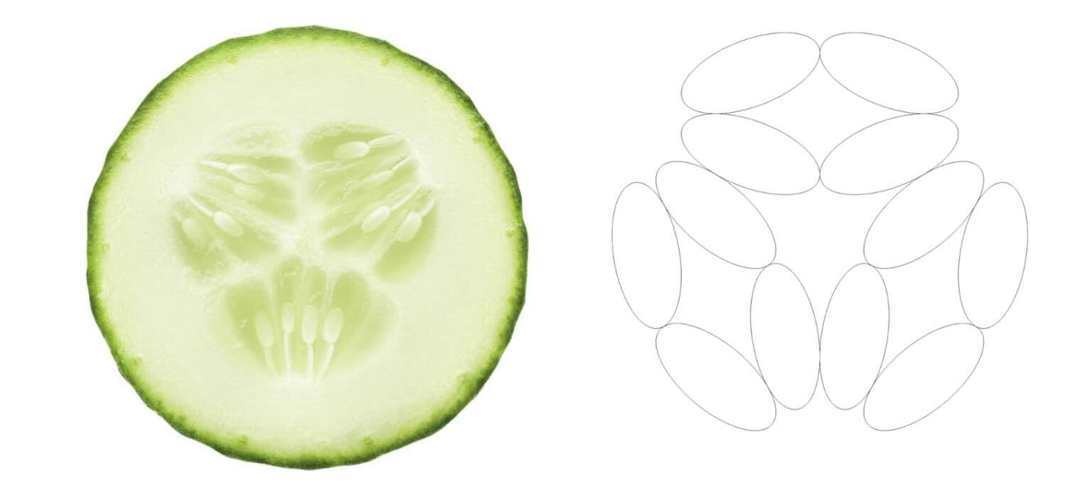
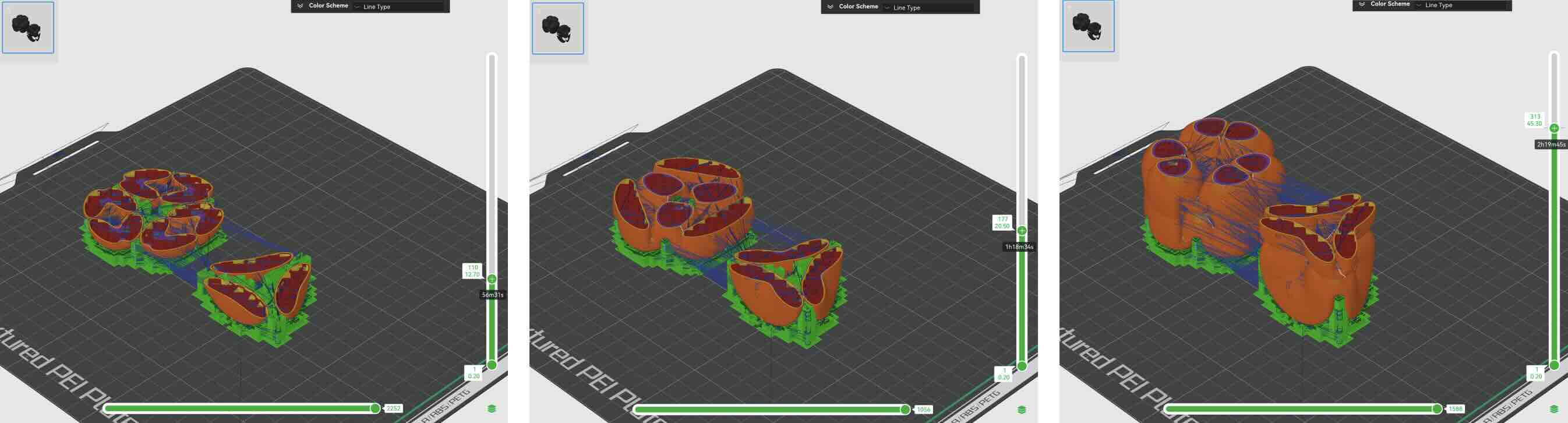
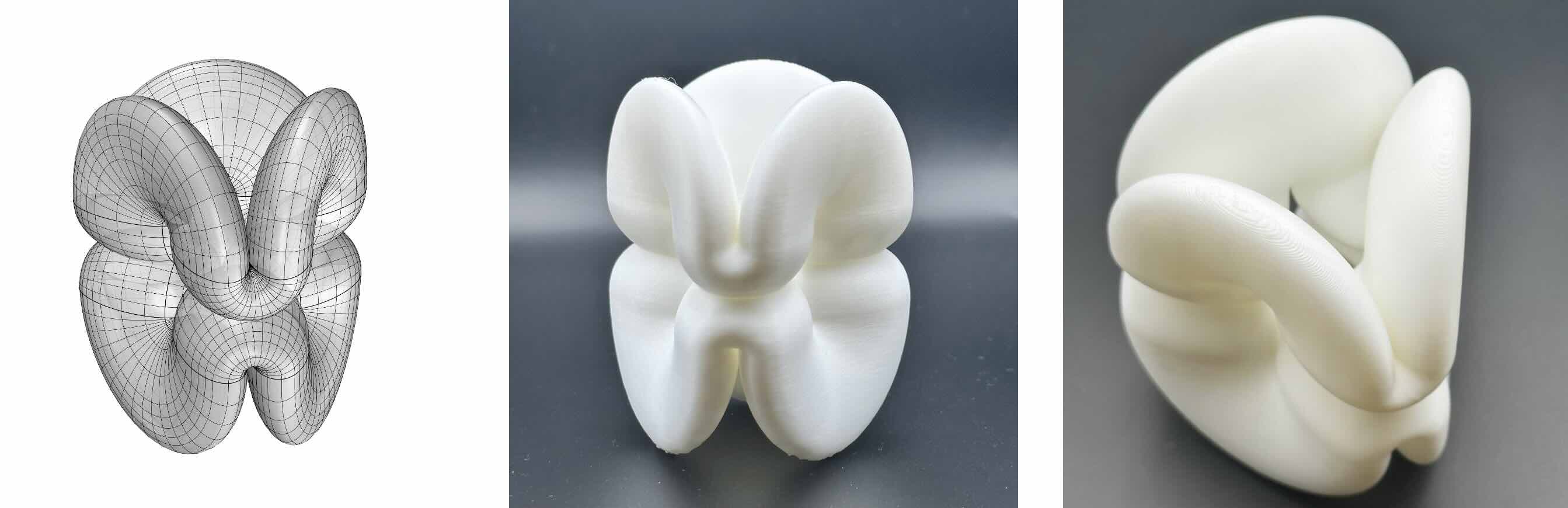
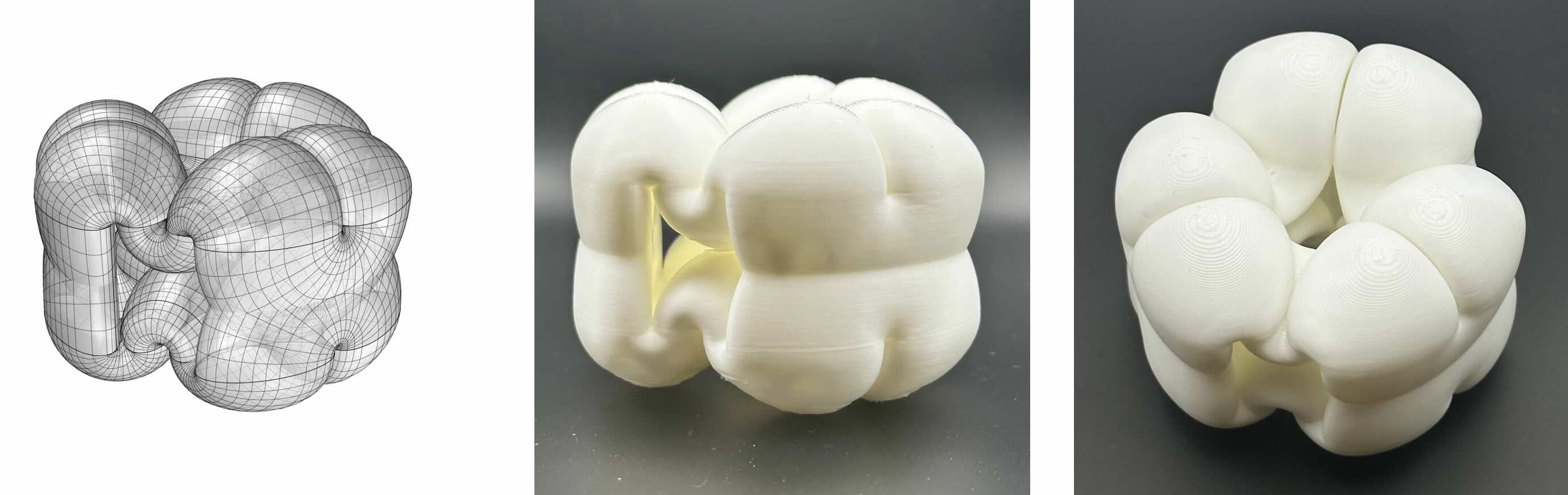
Once the digital model was complete, I exported selected geometries as .stl files and brought them into BambuStudio. There, I prepared the .gcode with a 15% rectilinear infill and minimal supports—only on the build plate—since the overhangs and bridges in my design were gentle and remained under 40 degrees. The result was a structure that captured the organic elegance of its natural inspiration while remaining efficient in fabrication.