Please see this link for my group's assignment (session 1).
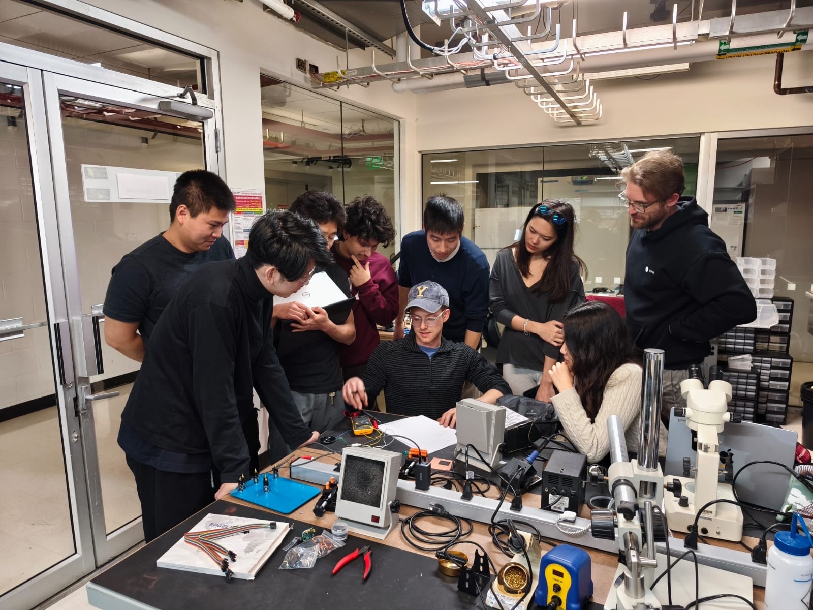
This week, I started making some incremental progress towards my final project. The idea is to build a modular synthesizer out of found electrical components, which teaches the user how to probe for different kinds of signals. A speaker will provide auditory feedback, which will enable the user to hear the different kind of output signals, while a screen will show them visually what the different signals look like. My goal for this week was to design a PCB using a microcontroller to generate sound.
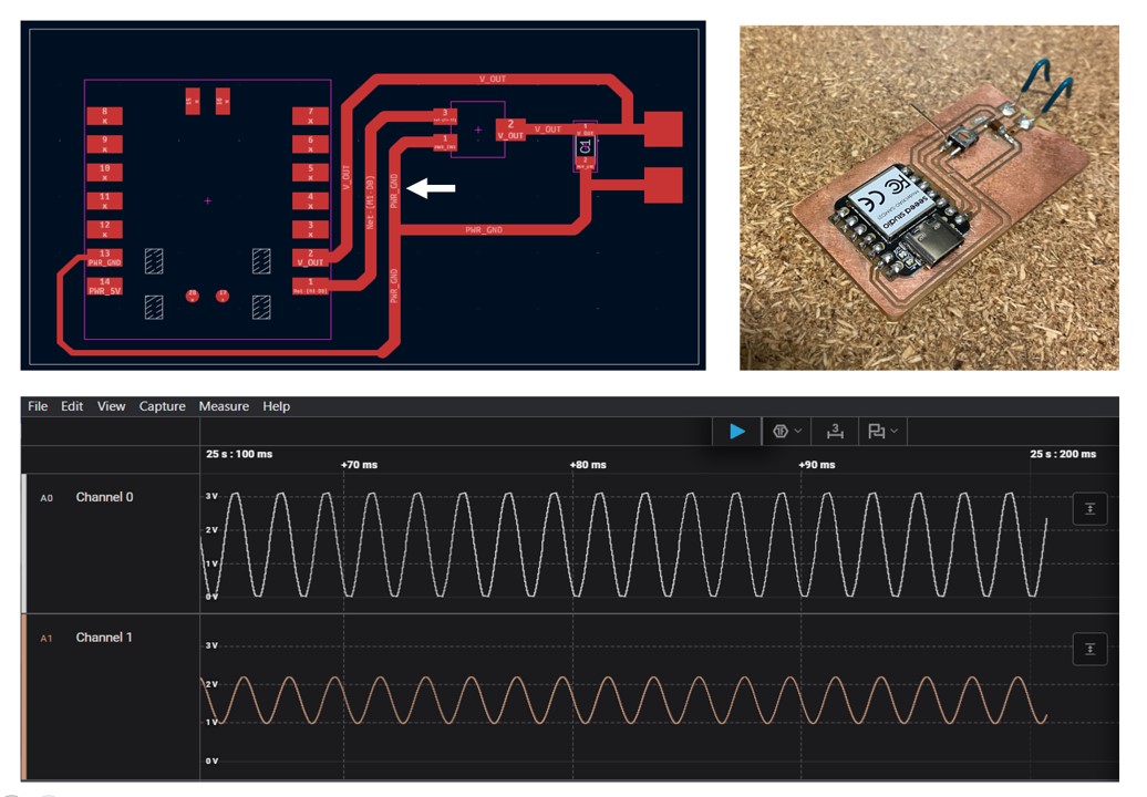
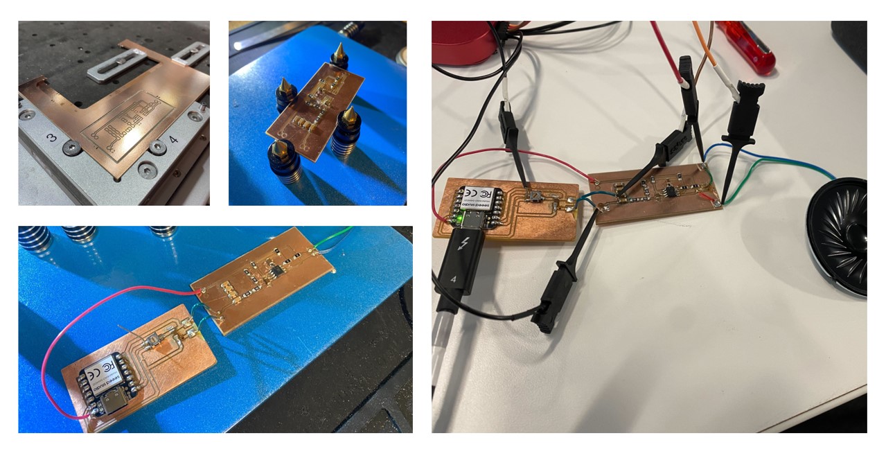
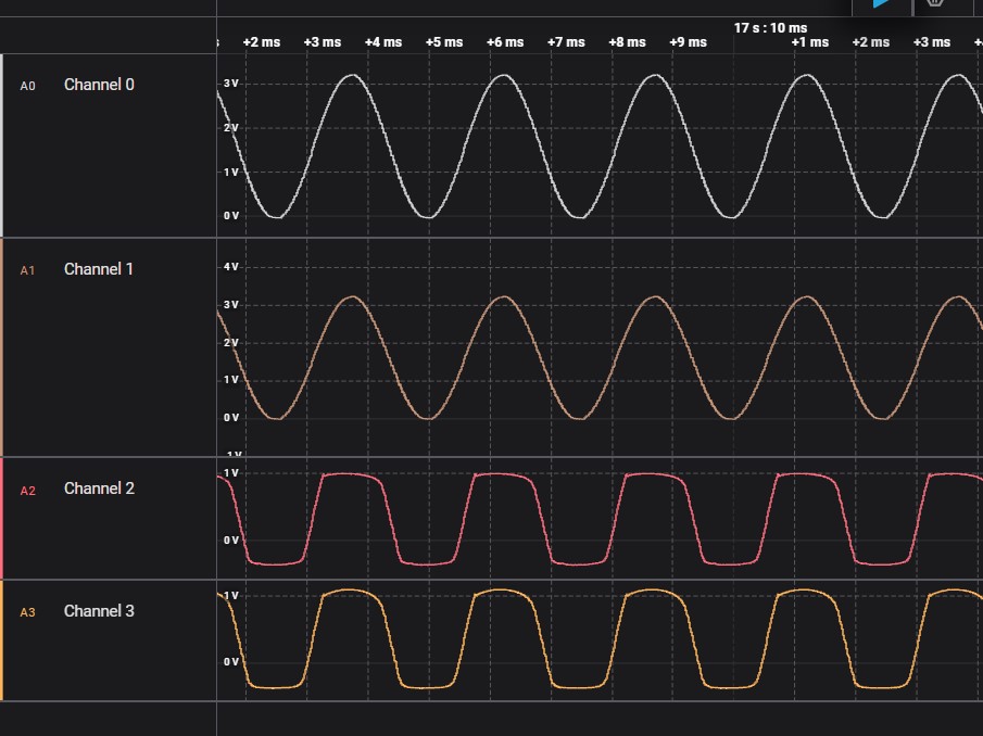
As a starting point, I wanted to fix my board from Week 6. This board simply feeds the output of thee SAMD21's DAC through a variable low pass filter. For some reason, I was not able to demonstrate a frequency response. I showed the board to Neil in class, and he was able to identify the issue rather quickly. I had grounded the third leg of my potentiometer, turning it into a voltage divider as opposed to a variable resistor. Cut the trace marked by the white arrow fixed this problem. The screenshot of my logic analyzer shows the input signal generated by the DAC on channel 0 and the output of the low pass filter on channel 1.
In order for this signal to be playable through a speaker, I would need to amplify it first. There are many different ways to amplify audio signals, as discussed in class. I decided to check on the inventory in the electronics lab to see which of the chips were available. The first one I spotted was the LM4871M Boomer, a 3W Audio Power Amplifier. Taking a quick look at the datasheet showed this to be a rather straightforward circuit, so I decided to go with it!
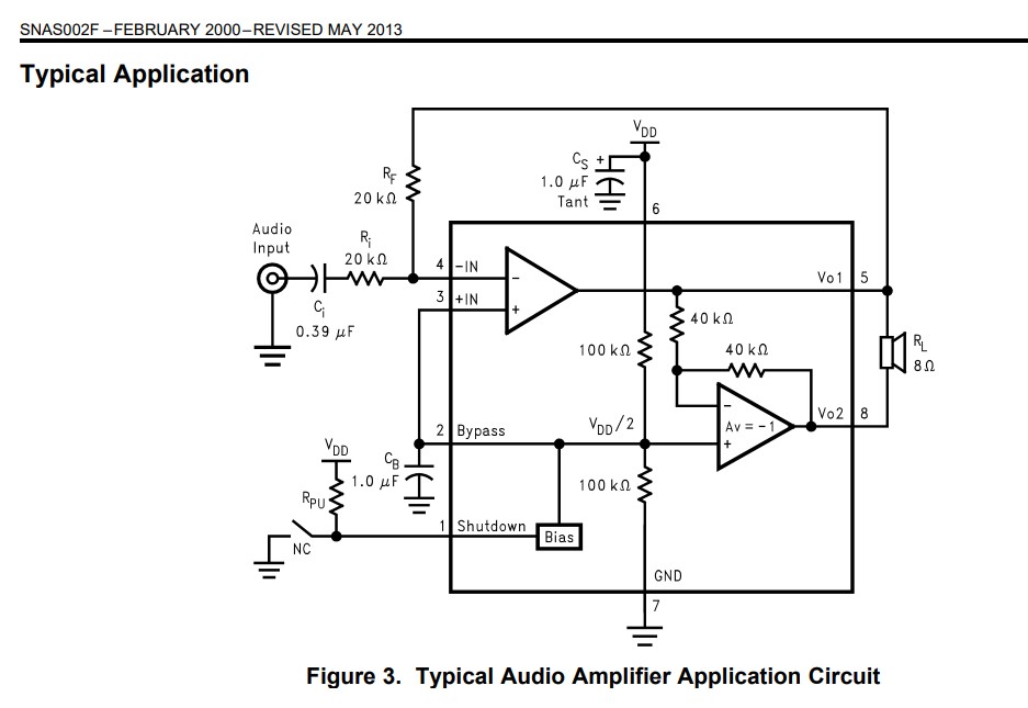
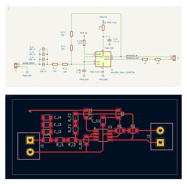
I duplicated the typical application circuit above, making sure to utilize the RC values we had available. For instance, since we didn't have any 0.39 uF capacitors on hand, I placed 4 0.1 uF capacitors in parallel to achieve the same effect.
I am getting more comfortable, moving through the workflow from schematic, to PCB layout, and through the Carvera milling process. That being said, one issue I had with my board is that the carvra did not mill out the through holes in my design. I believe this is because I did not export those features properly. I plan to work through this issue on my next board. For this week, I decided to make this board work through a bit of arts and crafts, using an exacto blade to make larger pads to which I could solder my input and output leads.
Alas, unfortunately, the board did not work at first. I probed around using an analog/digital logic analyzer. It appeared as though my input signal was making it through to the output pins of the amplifier IC, but the output did not look right (see below). Channel 0 is the output of the DAC, Channel 1 is the output of the RC circuit, Channels 2 and 3 are the LM4871M's two outputs. I was working with TA Alan on this during Friday's office hours when Neil popped by. He suggested that I use an H-bridge instead, following this example. from the HTMAA website.
At first, I did not see a schematic or footprint posted for this example, so I did my best to reverse engineer things based on: 1. a screenshot from the example video, 2. the the TB67H451 Datasheet and 3. the example code.
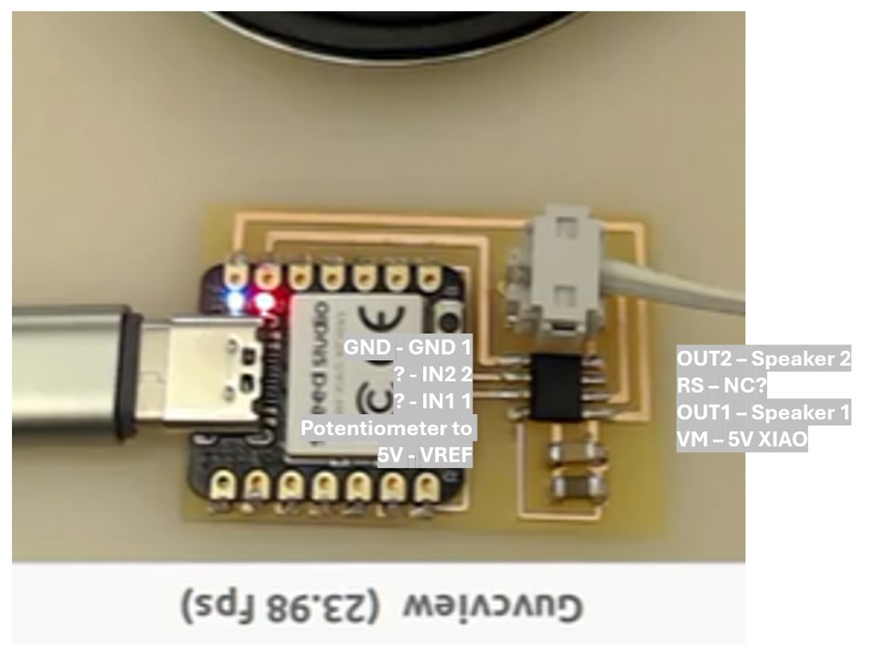
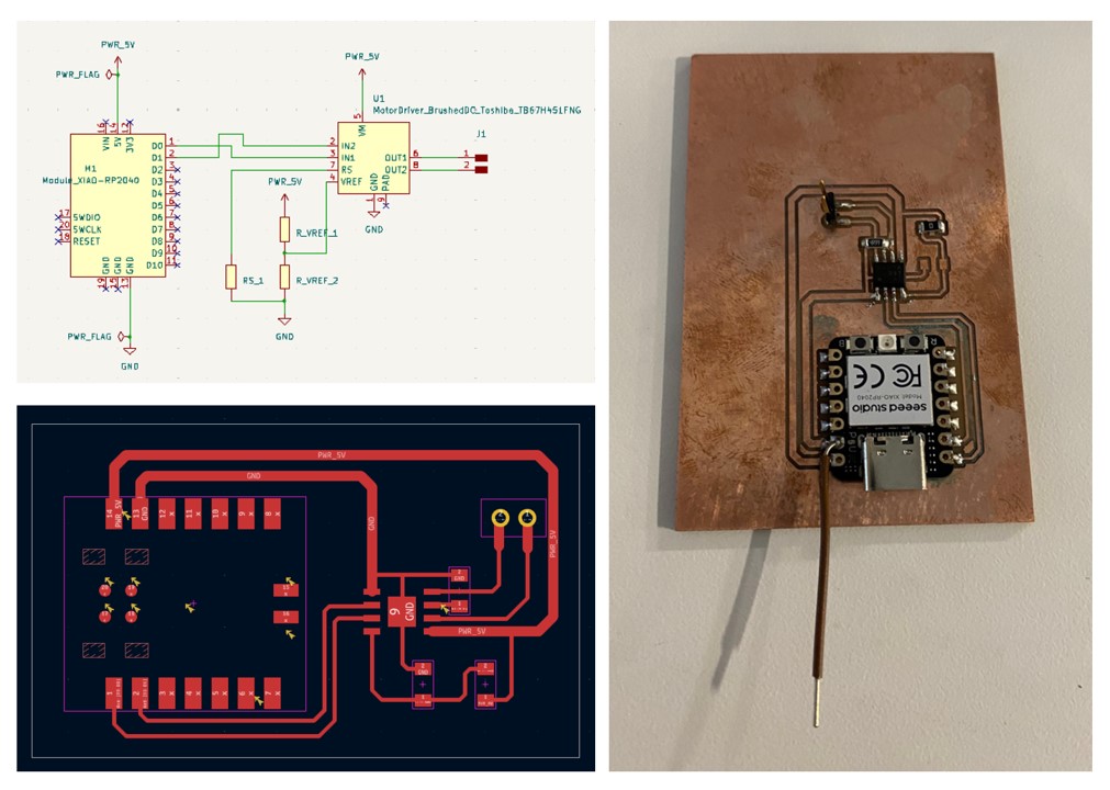
It was only after I went all the way through the milling process that TA Anthony pointed out to me that the foot print of the board in the example is shown under the H-bridge section of the output devices page. Alas, this was good practice with reverse engineering! The only major difference between my board and the example board is that I used D0 and D1 for my outputs where as the example uses D6 and D7. I was hoping that after updating the output pins in the code, this would simply work! Silly me...
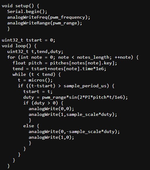
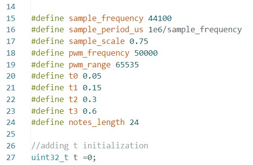
It took quite a bit of time, but ultimately, we figured out the issue. In the example code below (hello.TB67H451.RP2040.wave.ino), "t" is instantiated but not assigned a value. As a result, on my device, "while (t < tend)" never evaluated to true, so none of the code within the while loop would run. Instantiating AND assigning t = 0 at the top of the script solved this issue. After fixing this, my speaker finally made sound! The arduino file with these two adjustments can be downloaded here. All of the PCB files (including KiCAD project files and Gerbers) can be downloaded here
At this point, I had successfully closed the spiral on “make an output device”, but with Anthony by my side, I was feeling inspired! Did you know that we are both twins AND were both at Yale between the years of 2016-2019!? Neither did we!
We went back to look again at my initial design using the LM4871M amplifier. Anthony, with his eagle eyes and multimeter skills, hypothesized that there was a break in the trace connected to the amplifier's power input. In other worlds, the amplifier was off. Looking under a microscope, I was able to confirm that there was indeed a break in the trace.
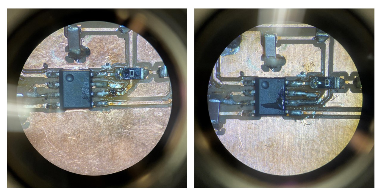
I performed some electronics surgery under the scope and was able to confirm with the multimeter that the power pin was indeed now connected. Right before plugging the USB in to test it, I said “hopefully nothing blows up!” Big mistake. Not only did I likely jinx myself, but in reality, I think I was compelled to say this because my engineering spidey sense told me, “don’t just plug things in, check to make sure your circuitry makes sense one last time.” Ignoring this instinct is never a good idea. But I don’t claim to be a perfect engineer. I clicked the USB into place and POOF, magic smoke emanated from my board. For those unfamiliar with this kind of “magic smoke”, this is not a good thing. Upon closer inspection, I realized that I had flipped my PCB (see below), and thus connected its outputs (intended to be connected to the speaker) to the 5V line, thus exploded the LM4871M which I had just surgically rehabilitated.
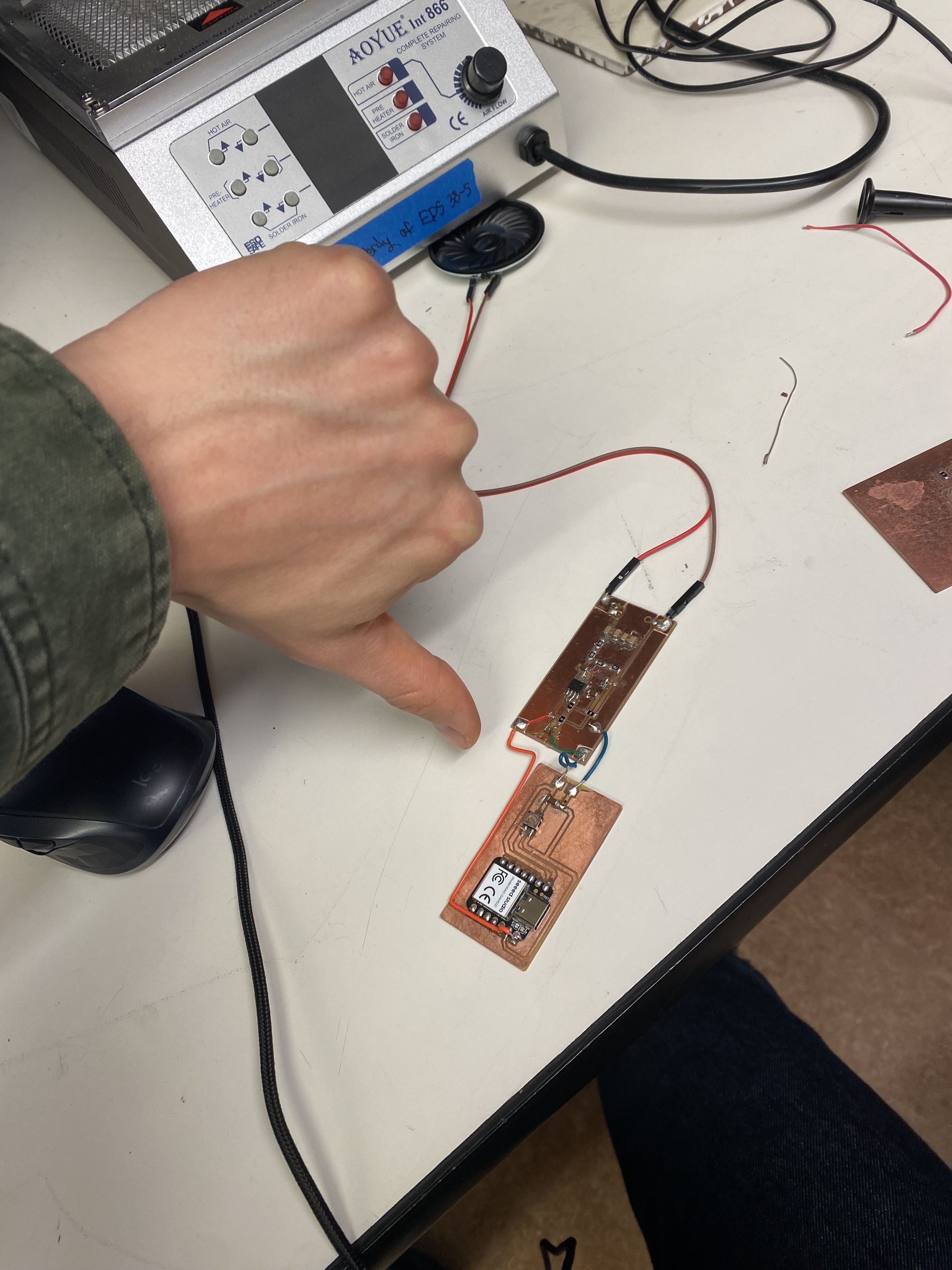
Silver lining: Anthony showed me how to use hot air to easily replace LM4871M, which was way easier than expected. At this point I carefully went through the circuit, ensuring that each leg of the IC was connected to the appropriate signal. When I plugged in the XIAO, the power pin was blinking on and off at a rapid rate AND it no longer showed up on my computer when I plugged in the USB. Anthony, once again, saved the day with a critical lesson: I was using the USB-A output of my computer to power the XIAO. You can pull significantly less power from a USB-A port as compared with a USB-C port. Since my amp was now connected properly and thus drawing power, my system was now exceeding the wattage available from my USB-A port, causing the XIAO to brown out over and over again. Simply powering the board from my USB-C port solved this problem, and voila, the speaker made sounds!
I was using a piece of code I'd written back in week 6, which outputs a sine wave sweep. This sounded okay, but wasn't quite what I wanted. It was at this point that I decided to take my initial dive into using ChatGPT to write code. Honestly, I feel a little behind the curve on this, but after many hours spent on the board design, fabrication and debugging, this felt like a good opportunity to explore collaborating with chat on code.
My initial prompt was: "Please write an arduino .ino file which uses the DAC pin on a SAMD21 XIAO to sweep up and then down over a range of frequencies. Define the range of the sweep using freq_start and sweep_stop. Also include a variable which enables me to control the period of one full sweep."
I was impressed with the speed at which it produced a script...but ultimately not impressed with the output. It sounded worse than my code! I decided to stick with it though and I have to admit, I was indeed impressed by the final output. My subsequent prompts, refining the code were as follows. You can also find the full transcript of the conversation here.
This is the linear sweep in frequency produced after the 2nd prompt above. The arduino file can be downloaded here chat_sweep_v3.ino
This is a logarithmic sweep in frequency and was produced by the final prompt above. The arduino file can be downloaded here chat_sweep_v4.ino
All of the PCB files for this second board (including KiCAD project files and Gerbers) can be downloaded here HW9_PCB_V2.zip
Return to Home Page