Earbud Earrings — Final Project Milestones
This page documents the current state of my HTMAA final project: earbud earrings — a wearable, jewelry-like audio concept that evolved into a more feasible prototype: the Magic Earring.
Motivation: Turning Earbuds into Earrings
Accessorizing in the modern world is a surprisingly difficult task. Like many Elle Woods fans, I dream of perfect outfit coordination — the kind where every accessory feels intentional.
But in practice, utility often gets in the way of style.
I spend my days hopping in and out of calls, tuning out the bustle of coffee shops and libraries, all thanks to my trusty earbuds. They’re indispensable — but they rarely look the part. They dangle awkwardly when not in use, clash with carefully chosen jewelry, or disappear at the bottom of a bag.
This everyday mismatch between style and function sparked an idea: what if earbuds could become earrings? Instead of treating them as an afterthought, why not design them as intentional accessories — elegant, wearable, and always at hand (or rather, ear)?
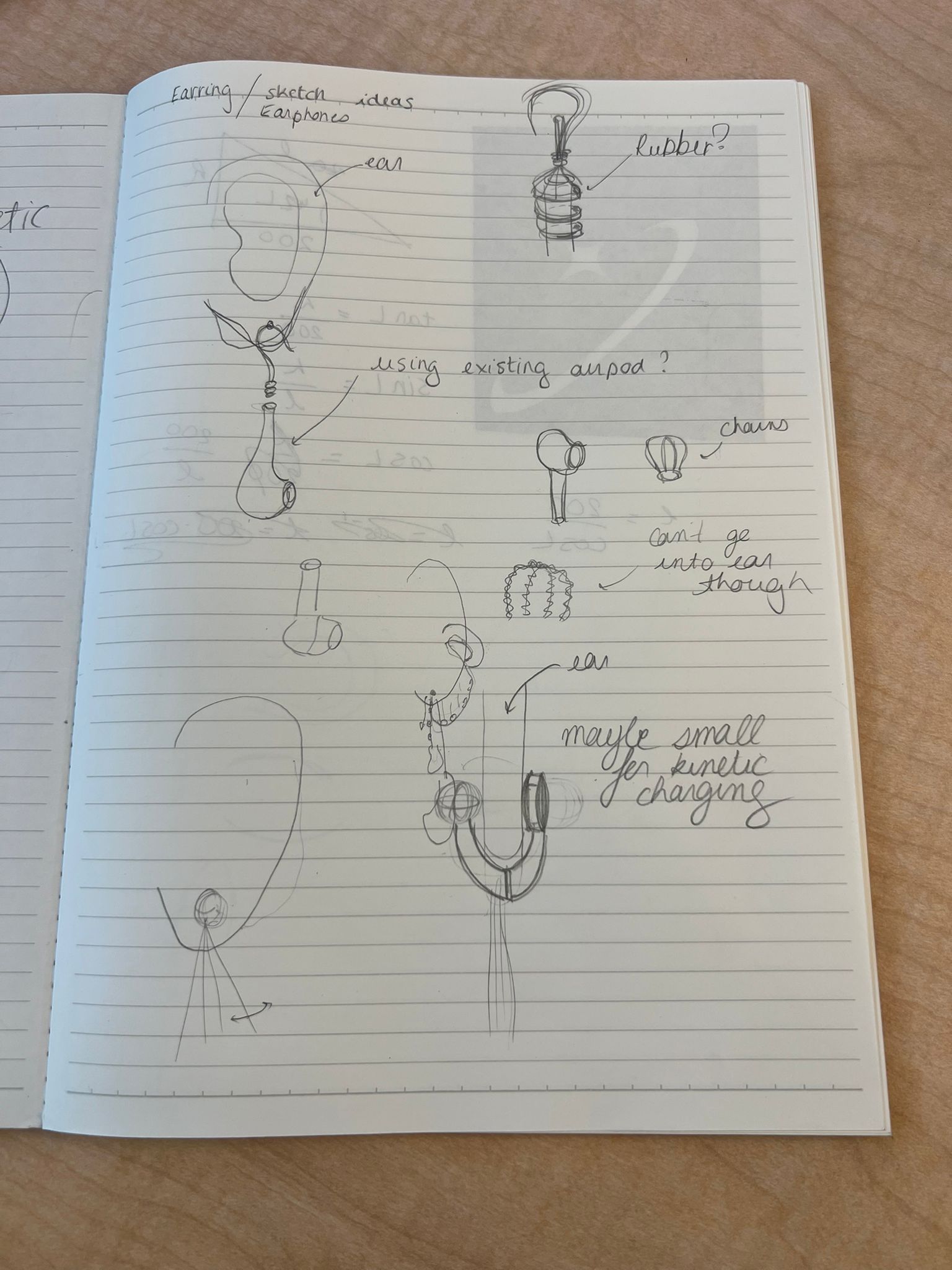
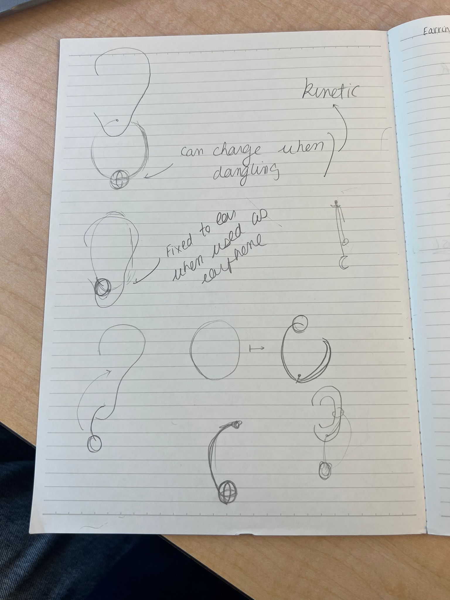
Brainstorming & Initial Concept
The initial idea was ambitious: earphone earrings that could charge themselves kinetically. The vision was to harvest energy from everyday motion — walking, turning, even dancing — and use it to power a pair of elegant wireless earbuds that double as jewelry.
It felt like the perfect marriage of fashion, technology, and a bit of sci-fi optimism.
Researching Existing Designs
Before diving into feasibility, I reviewed products and concepts that reimagine wearables and audio:
- Zhang Yunxib’s designs — playful, sculptural forms that reimagine everyday electronics.
- Yanko Design collection — alternative earbud form factors and housings.
- Nova Audio Earrings — pearl earrings that are fully functional Bluetooth earbuds.
Exploring Kinetic Charging
One of the most exciting (and challenging) ideas was kinetic energy harvesting. Building on the piezoelectric effect (first identified by Pierre and Jacques Curie in 1880), I explored whether motion could meaningfully power earbuds.
Reading & References
- Piezoelectric energy harvesting overview (ScienceDirect)
- Can we harness electricity from human movement? (Medium)
- Hybrid human-motion energy harvesting techniques (ScienceDirect)
Human movement is irregular, and most piezoelectric harvesters output on the order of microwatts — far below typical earbud power needs.
Because of this intermittent and low-power output, it became clear that relying solely on motion-based harvesting for v1 would not be realistic. A secondary charging method (wired) would be needed, with kinetic harvesting reserved as a possible augmenting feature for future versions.
Conversations with TAs: Reality Check
Anthony: “I cannot understate how hard it is going to be to get energy harvesting like this to power a pair of headphones.”
Using numbers from recent literature (best-case ≈ 67 µW harvested), Anthony estimated this to be roughly ~500× lower than what a single earbud would need. As a rough mental model, charging an AirPod-class battery via motion alone would correspond to something like ~1,500 hours of motion for one earbud (and more once you include conversion losses).
Gert: “Scope the fundamentals first: power budget, a microcontroller with Bluetooth that won’t weigh down the ear, and sensor choices.”
Gert’s advice helped break the problem into a more manageable roadmap, and made the scope constraints clearer for a one-semester build.
Pivoting the Project
Given the constraints, I pivoted away from full kinetic self-charging and refocused on the core experience: wearable “audio jewelry” with clear interaction. This kept the heart of the idea — intentional design — while making a v1 prototype feasible within HTMAA.
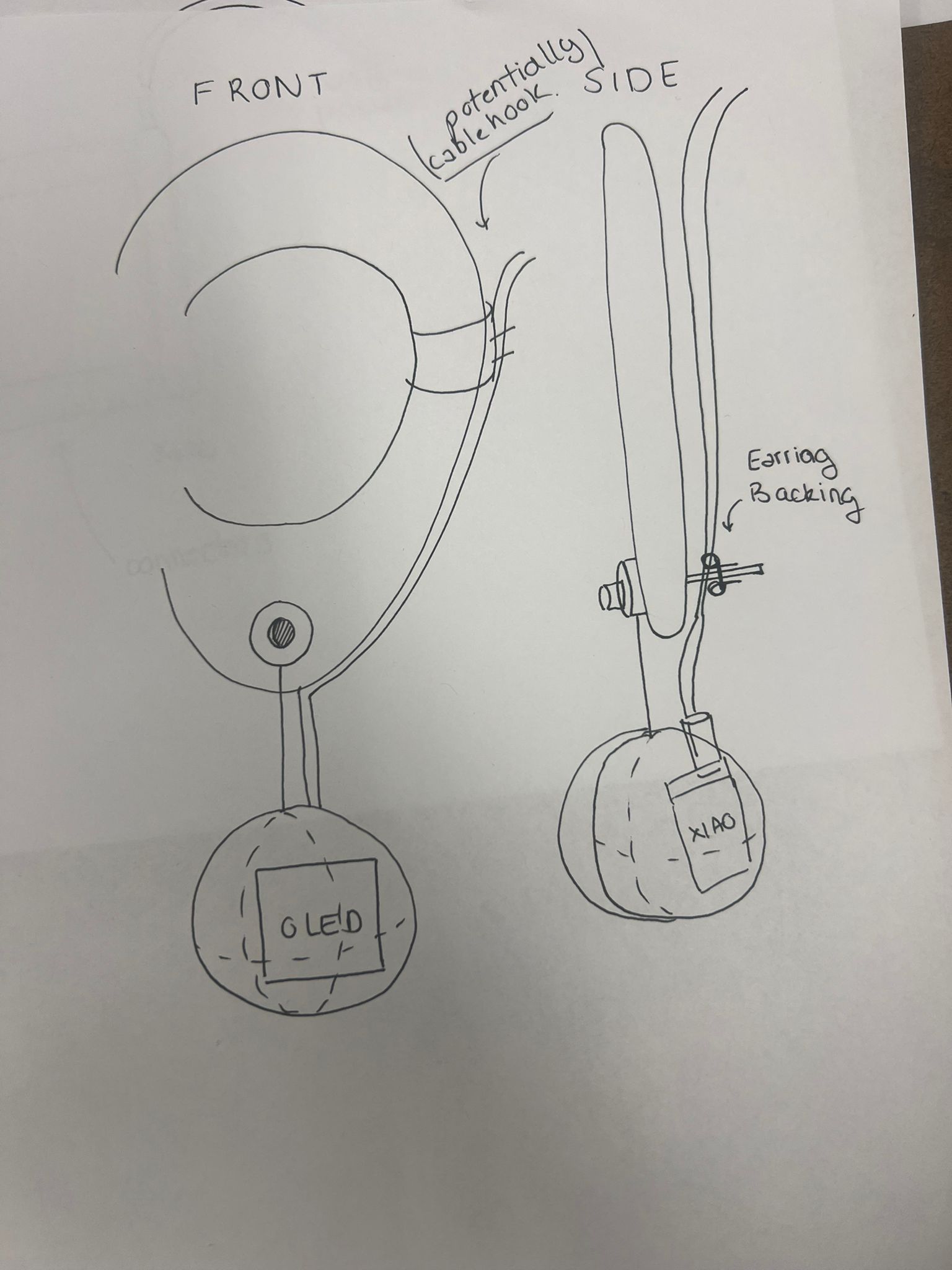
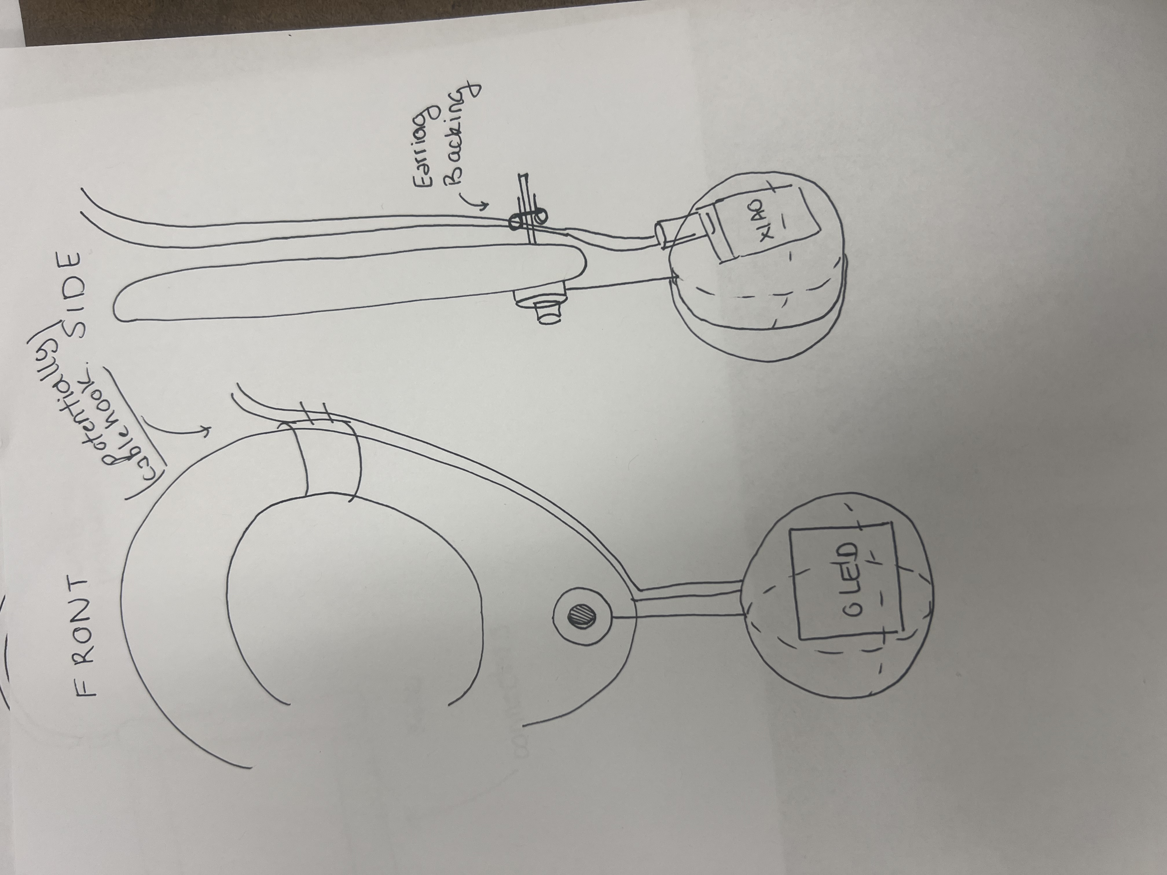
Next Steps (Design Process Preview)
- Form studies: 2D sketches and 3D-printed test geometries for weight, balance, and comfort.
- Mechanism: magnet/clip interfaces for quick transitions between “earring mode” and “use mode”.
- Electronics: evaluate MCU + BLE + audio options, amplifier, battery size, and wiring paths.
- Materials: experiment with resin/casting and finishes that read as jewelry.
- Charging (v2+): leave provisions in the design for future hybrid charging and energy harvesting experiments.
System Diagram
The project combines mechanical design, electronics, and embedded programming in a wearable form factor.
Tasks to Be Completed
To get from concept to a working prototype, I broke the project down into concrete tasks:
1. Mechanical / Industrial Design
- Refine overall form factor (enclosure geometry) in CAD.
- Design mounting/attachment points (hook/chain/strain relief strategy).
- Prototype shells (FDM/resin) to check weight, balance, and comfort.
2. Electronics Design & Production
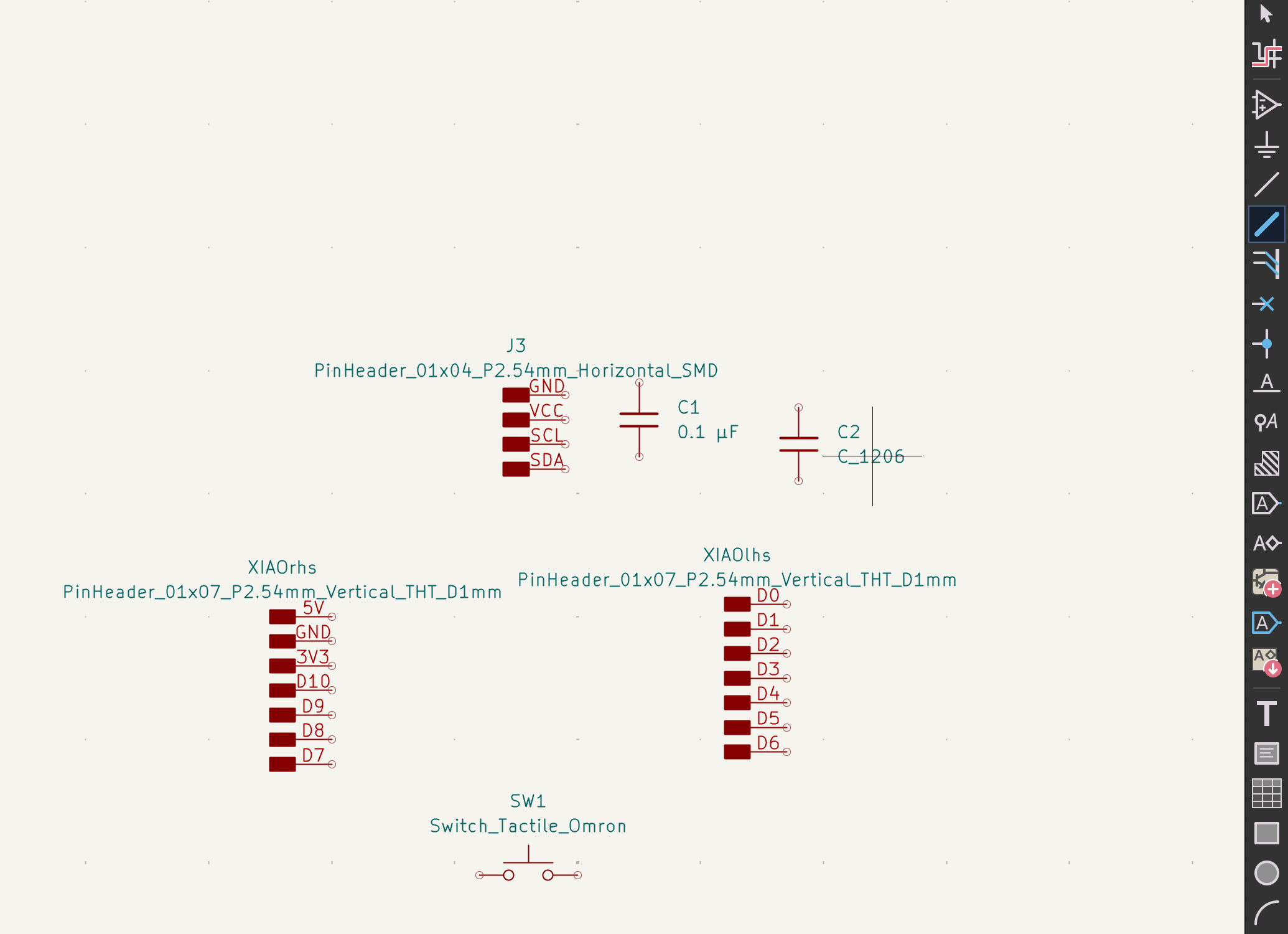
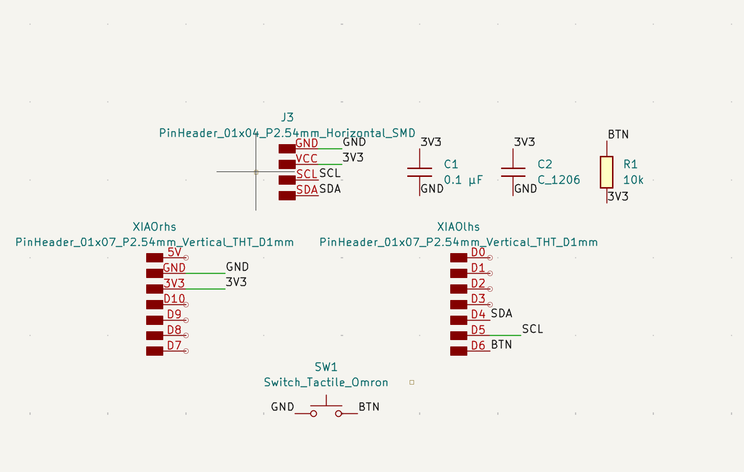
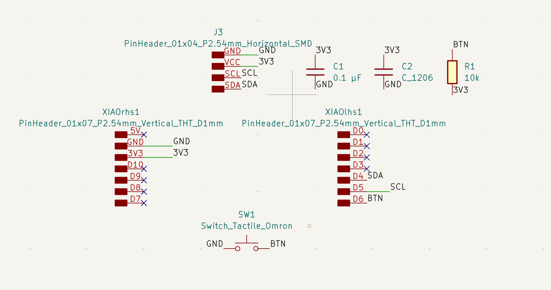
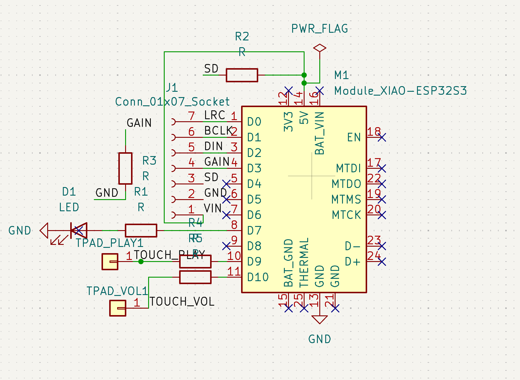
- Design schematic and PCB in KiCad for BLE + OLED + button + audio path.
- Route, export, fabricate, assemble, and rework.
- Debug power and audio bring-up.
3. Embedded Programming
- BLE advertising + service/characteristic + command handling.
- OLED display output for the selected response.
- Audio output verification (tone/clip) through amp + speaker.
4. System Integration & Packaging
- Integrate PCB and power into enclosure.
- Secure wiring, reduce strain, improve mechanical stability.
5. Evaluation & Documentation
- Comfort, stability, and usability checks.
- Document what works, what fails, and what to improve.
Project Schedule
The schedule below is a working plan toward a more robust prototype.
| Week / Dates | Milestones |
|---|---|
| This week |
|
| Next |
|
Instructor Meeting
Graded review meeting:
Scheduled with HTMAA instructors / section staff.
Agenda:
- Walkthrough of the system diagram and architecture.
- Review planned fabrication processes (2D/3D, electronics, assembly).
- Feasibility check on scope vs. timeline.
- Feedback on risks and potential simplifications.
Pivoting to a Magic Earring
After walking through my original “earbud earrings” plan in the instructor review, it became clear that a fully functional pair of streaming earbuds with custom mechanics and experimental power systems would be difficult to finish (and debug) at the level of reliability I wanted within the remaining time.
Instead of dropping the idea entirely, I chose to simplify the artifact while keeping the same core ingredients: custom electronics, Bluetooth connectivity, audio output, and a wearable, jewelry-like form factor. This led to the Magic Earring — a single wearable that behaves like a playful, Bluetooth-connected decision assistant inspired by a physical Magic Eight Ball.
BLE bring-up and custom protocol
I implemented a BLE server that advertises as AudioCharm with a custom service and characteristic, then used LightBlue to:
- Discover and connect to the device over BLE.
- Write bytes to the characteristic and confirm reception over serial.
- Iterate on the characteristic behavior until it was stable.
Any write to this characteristic is interpreted as “ask the earring a question,” which kept the protocol simple and robust. The BLE work is documented in more detail on my Networking and Communications and Applications and Interfaces pages.
Magic Eight Ball logic
On the firmware side, the write callback implements the Magic Eight Ball behavior. When a command arrives, the ESP32-S3:
- Uses a hardware random number generator (
esp_random()) to choose an answer. - Logs the choice over Serial for debugging.
- Outputs feedback locally and back to the client.
Two-way BLE with notifications
To let the browser show the chosen answer, I extended the characteristic from simple write to write + notify. After selecting an answer, it:
- Calls
setValue()with the UTF-8 text of the answer. - Calls
notify()so the connected client receives the update.
Web Bluetooth interface
To make the interaction tangible, I built a Web Bluetooth interface (HTML/CSS/JS) that connects, writes a one-byte command, and displays the response from notifications.
Immediate Next Steps
With the simplified concept defined and BLE communication working, the remaining work focused on audio playback, physical packaging, and integration.
1. Audio Playback (ESP32-S3)
- Confirm I2S pin mapping on the PCB.
- Write a minimal audio test to validate the amp + speaker chain.
- Map each Magic Eight Ball answer to an audio output (tone/clip).
2. Physical Packaging / Wearable Form
- Design a compact enclosure sized to the PCB + speaker.
- Include mounting and strain-relief features.
- Iterate geometry for comfort, balance, and access for debugging.
3. System Integration
- Mount PCB and speaker inside the enclosure.
- Secure wiring; prevent shorts and stress on joints.
- Choose a reliable power solution for demo and iteration.
Sprint sequence: audio → enclosure → integration → polish.
Last Week: From Concept to Working Hardware
With the Magic Earring behavior defined and BLE communication stable, the focus shifted from architecture to physical realization: a new PCB revision, real audio output, and the constraints imposed by making something small enough to be handled and worn (even temporarily).
This phase was less about adding features and more about discovering where schematics and real hardware diverge — especially in a compact, double-sided PCB that has to survive handling, rework, and “wearable reality.”
My goals were:
- Integrate: move from a prototype stack to a coherent board.
- De-risk: validate that power + audio + I/O can coexist reliably.
- Package-aware design: plan front/back orientation and component height from the start.
The main takeaway: for wearables, the PCB is not “just electronics” — it becomes a structural component, a thermal object, and a safety/comfort constraint.
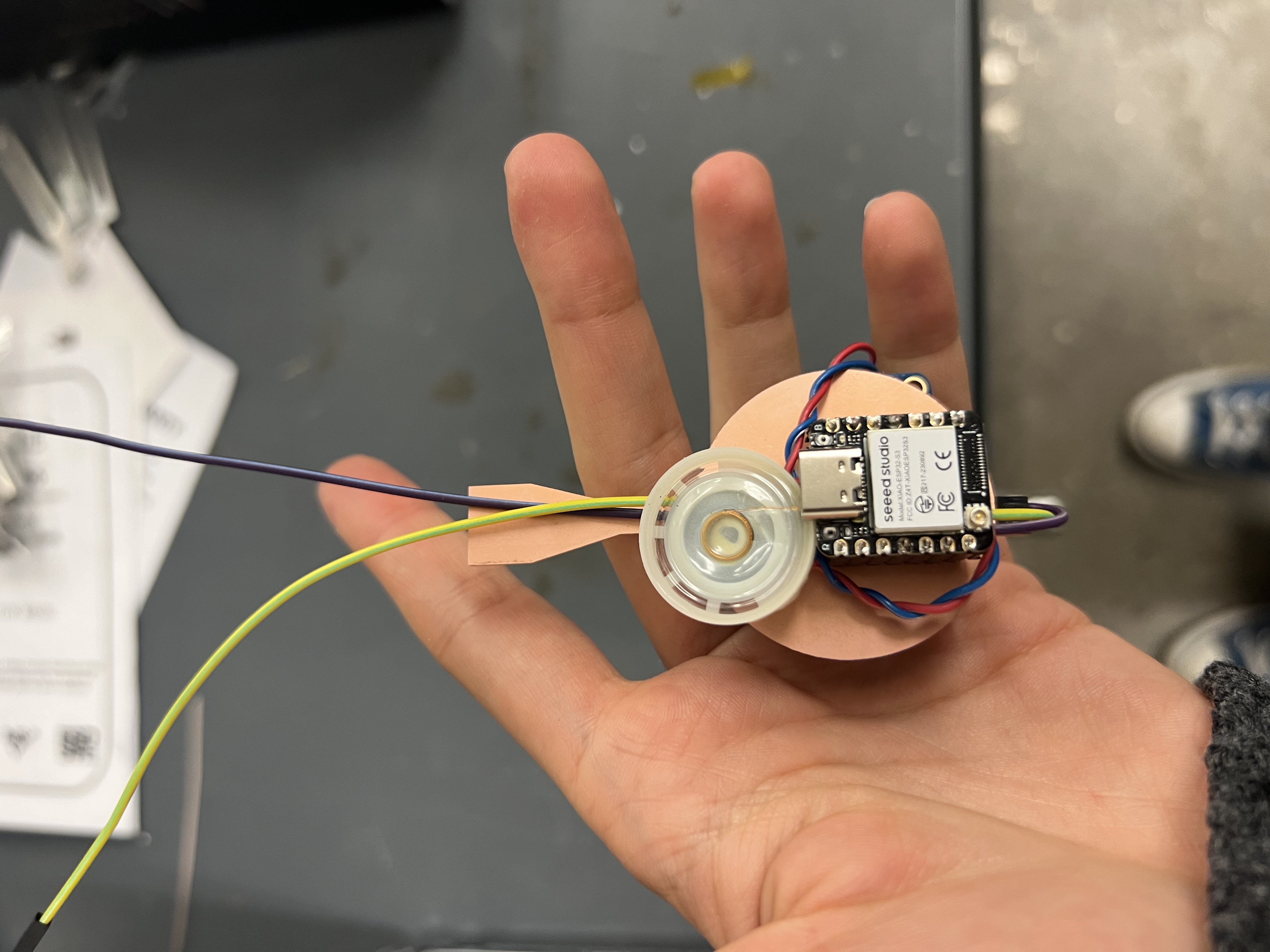
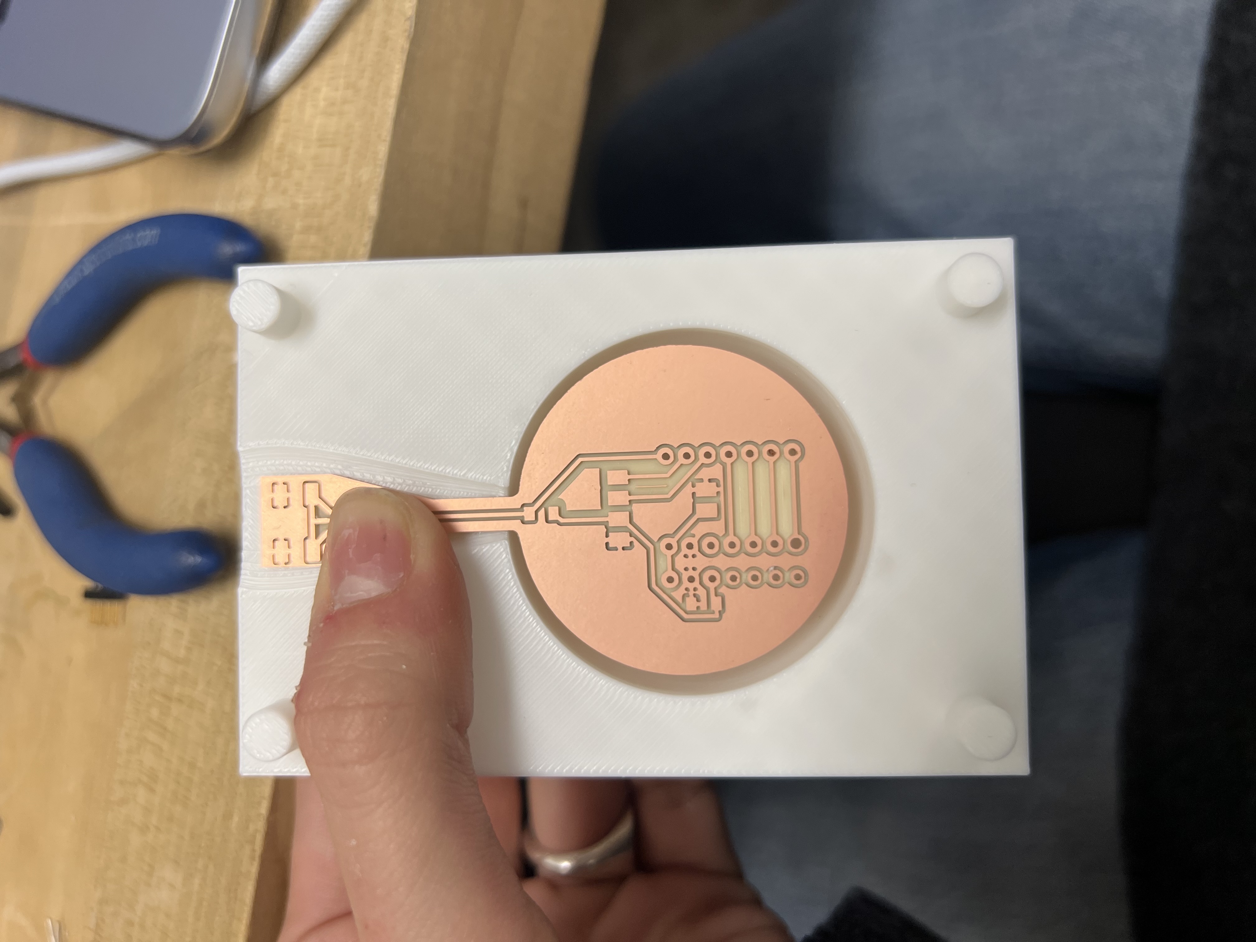
New PCB Design: Integrating Everything
To support the Magic Earring as a self-contained object, I designed a new custom PCB centered on the ESP32-S3. The goal was to consolidate the core stack into one board: a BLE-capable microcontroller, an audio output path, and user-facing I/O (OLED + button).
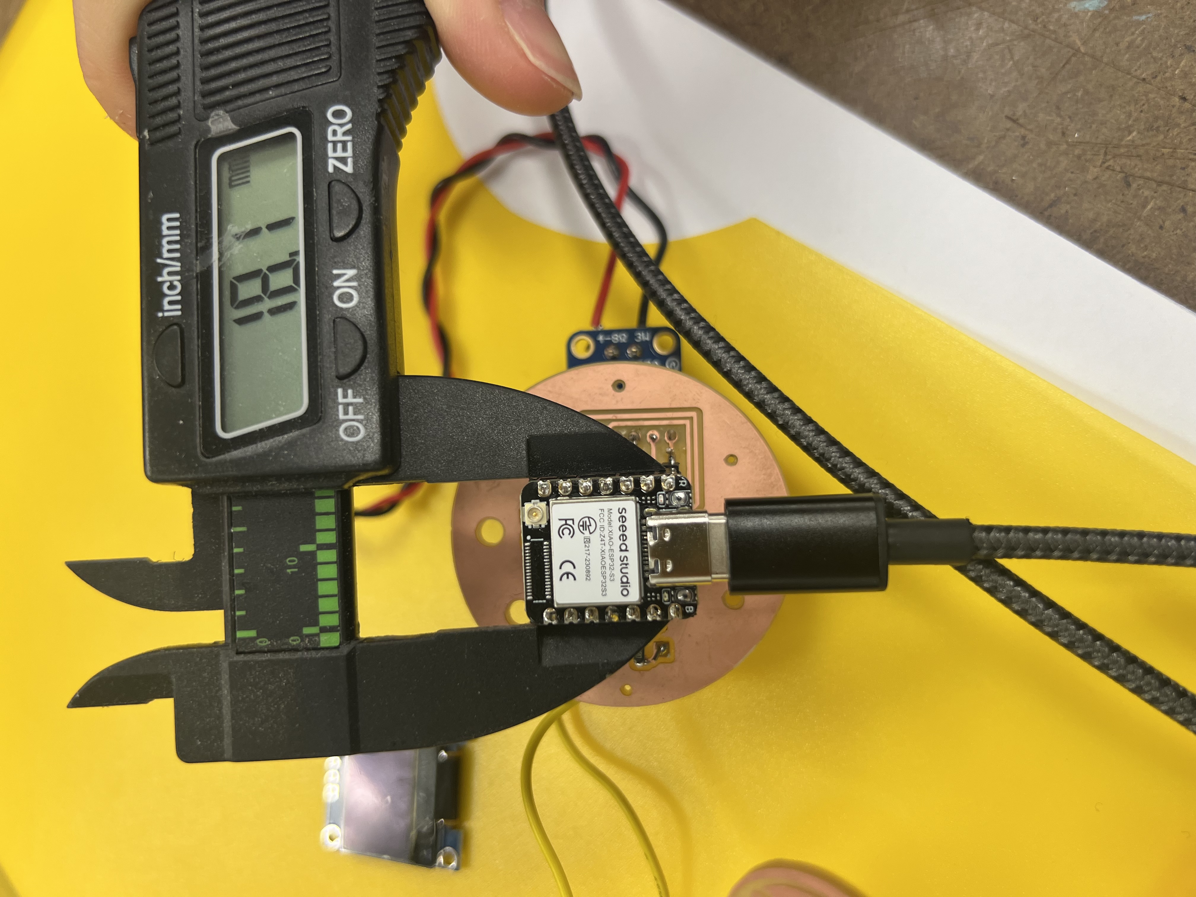
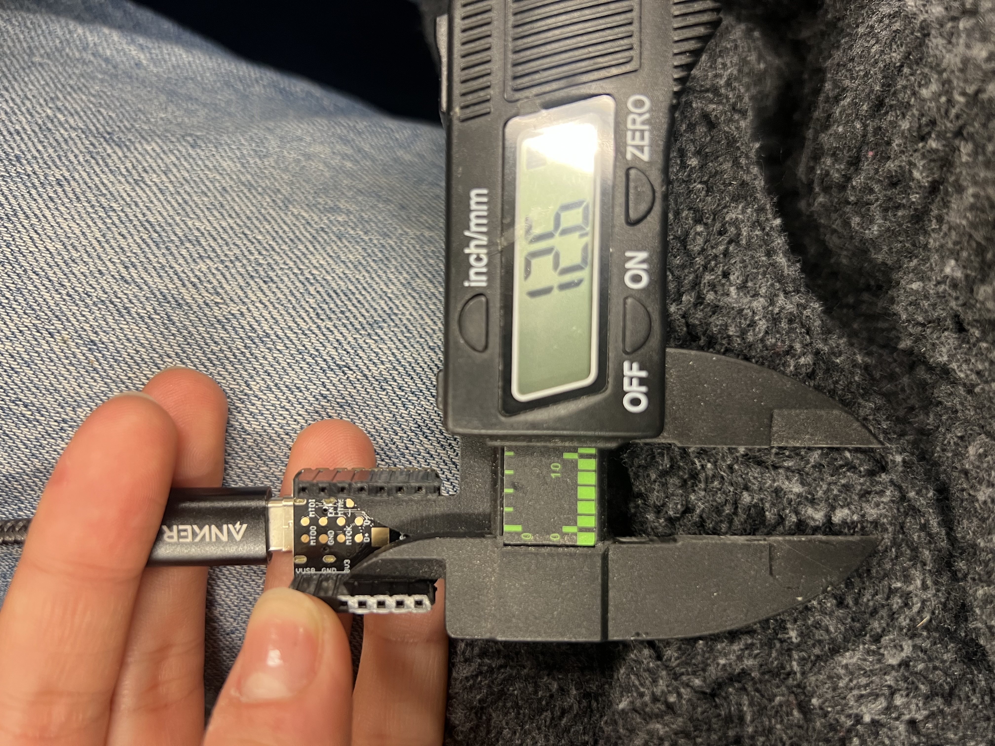
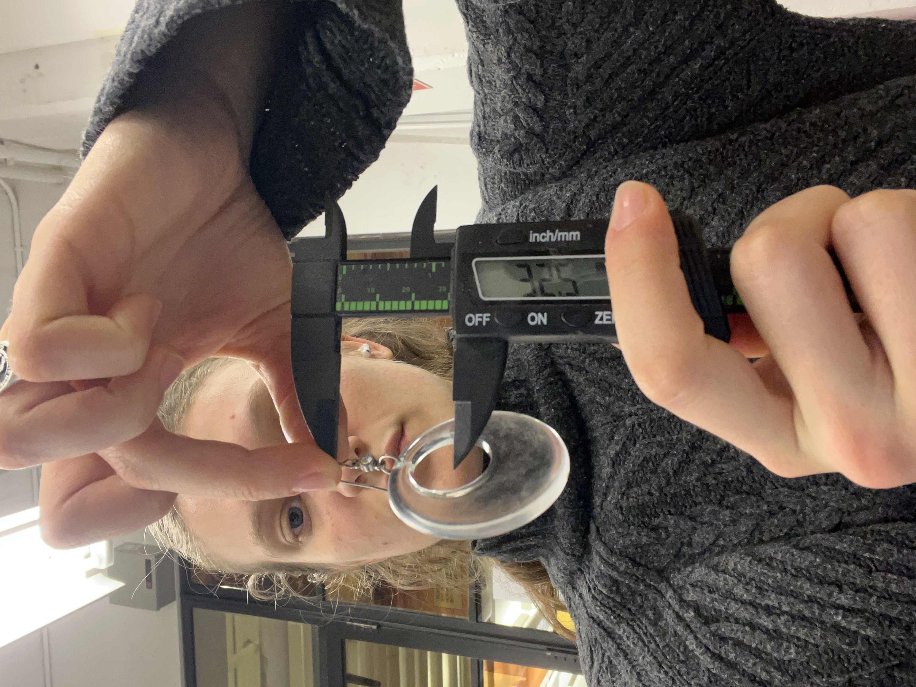
Constraints that drove the layout
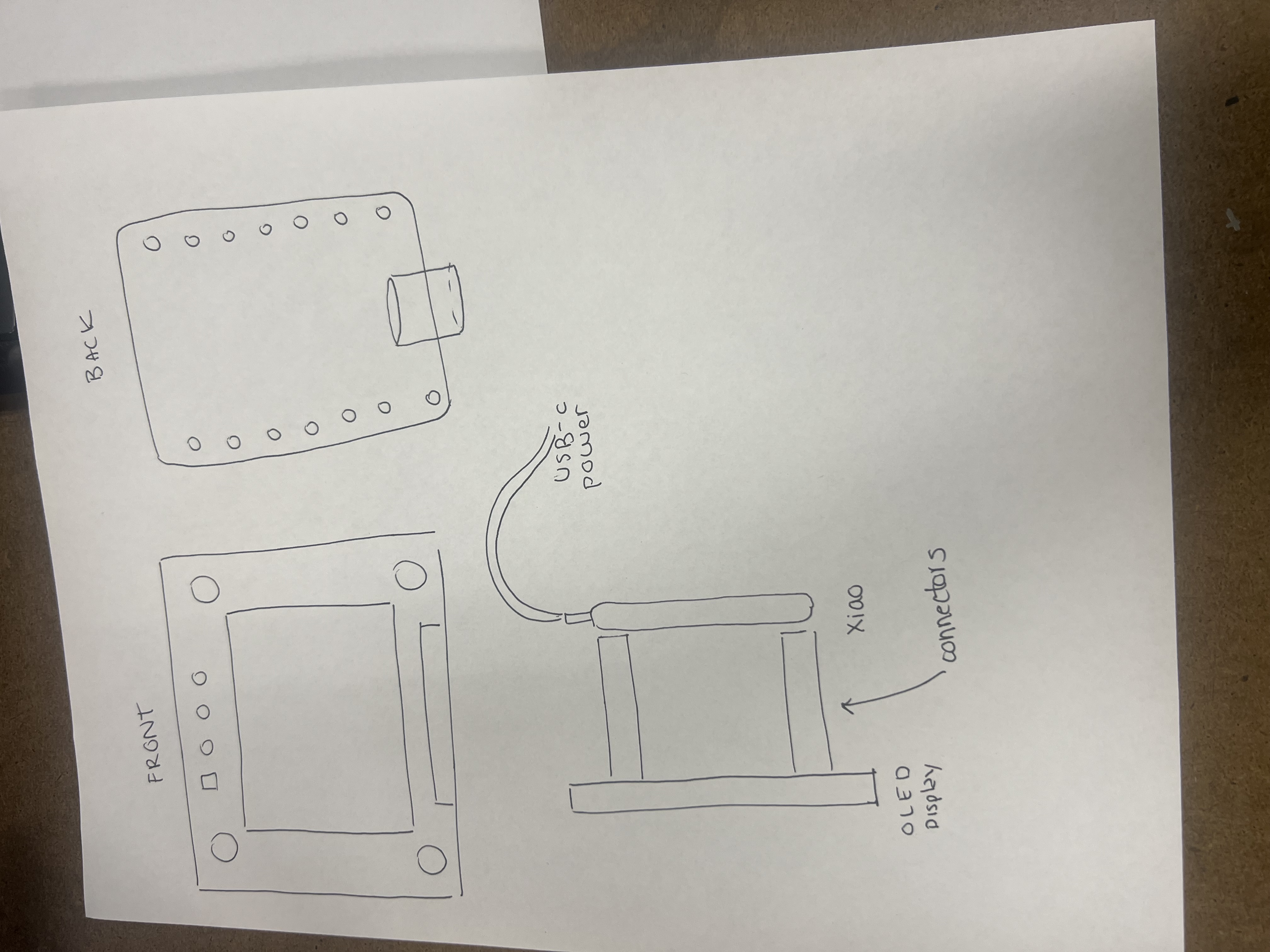
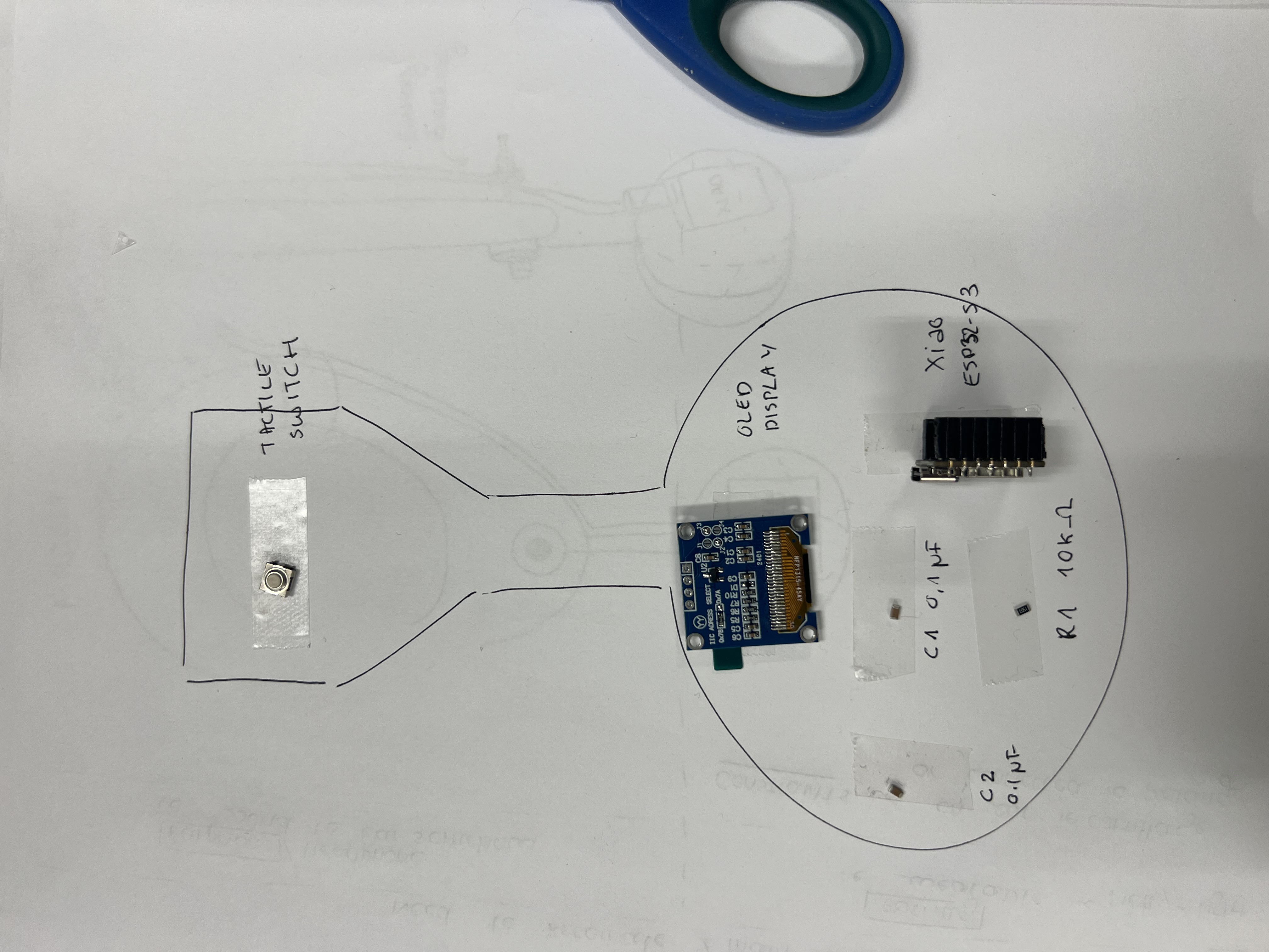
I started from mechanical constraints rather than electrical ones. Before opening KiCad, I measured key components and sketched how the object would be oriented on the body. These decisions drove connector placement, keepouts, and which components could exist on the body side.

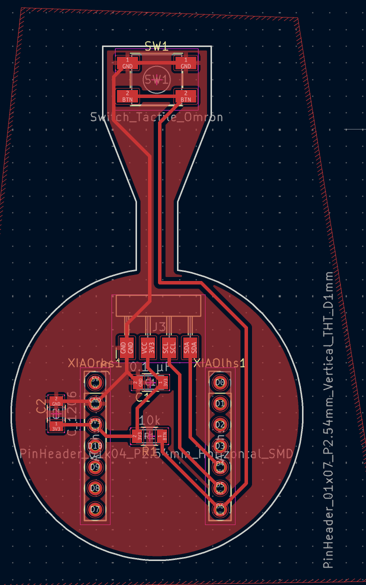
Why double-sided?
The board became double-sided out of necessity. Once the OLED and button entered the picture, board area vanished. Double-sided routing kept traces short and placement reasonable, but increased assembly complexity and failure modes (especially shorts).
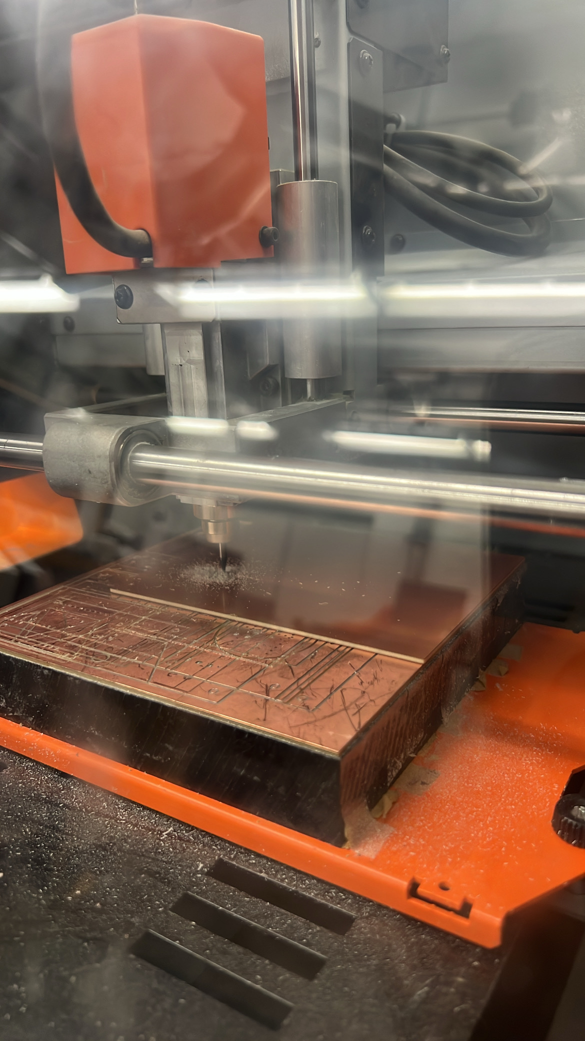
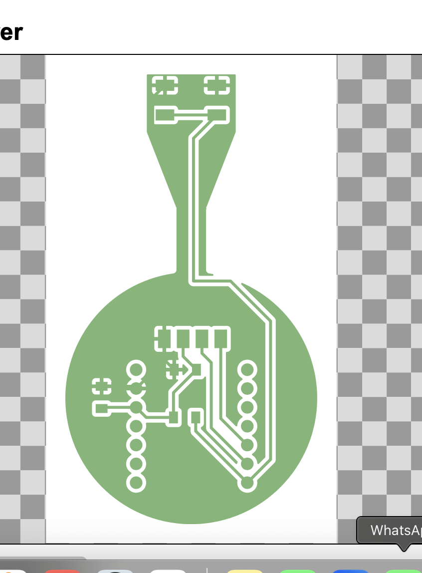
Fabrication (many tries) + first inspection
Milling took multiple attempts. Most failures came from using the wrong tip and from toolpath choices in MODs. After debugging (and help from Gert), I got clean boards and did an inspection pass before soldering.

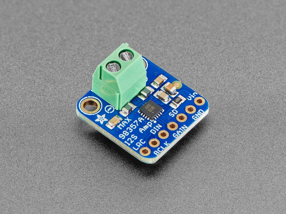
Audio path integration
Since the Magic Earring’s “magic” is partly auditory, I prioritized integrating the amplifier path early to reduce wiring fragility and make audio debugging systematic.
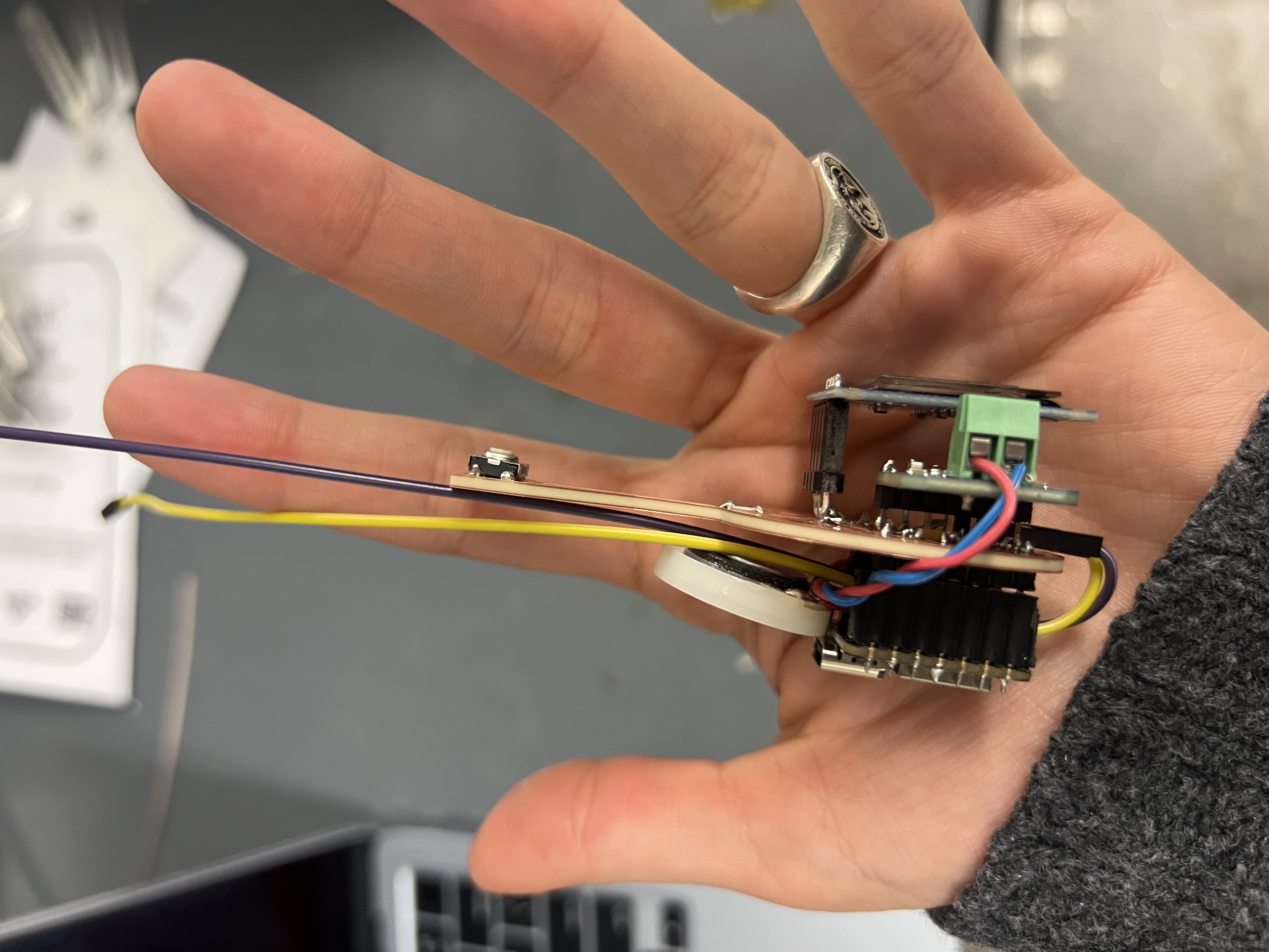
Assembly workflow
Soldering a dense, double-sided board requires sequencing. I staged parts, checked polarity/orientation before soldering, and ran continuity checks throughout.
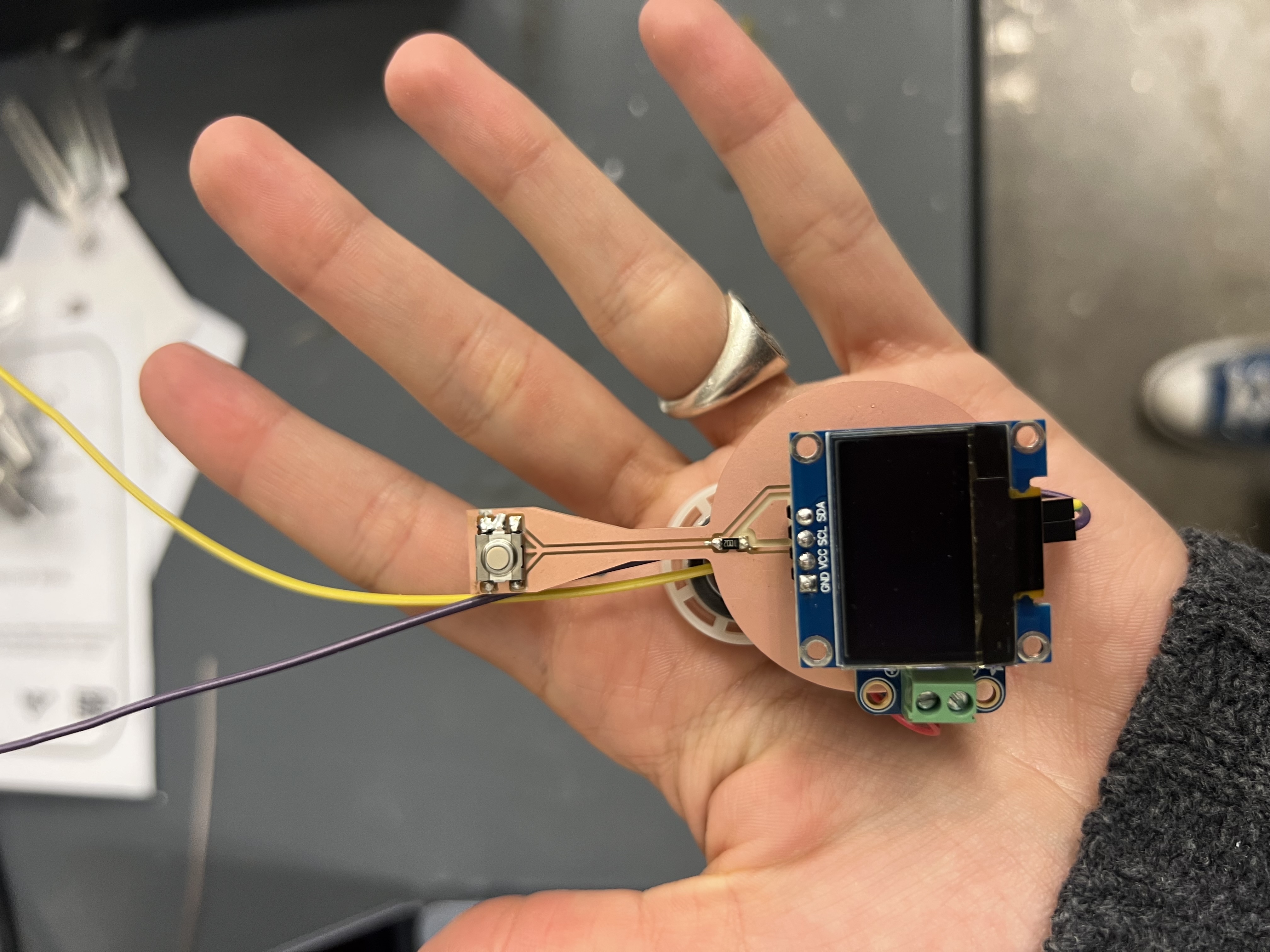
Adding an OLED + Button: Two-Sided Thinking
To make the Magic Earring legible and interactive, I added a small OLED display and a physical button. Together, these provide immediate feedback and a local interaction path when I’m debugging.
Adding these components was not just wiring I²C and a GPIO — it forced a shift in how I thought about the object. The device now has a front and a back: outward-facing readability/aesthetics vs. inward-facing comfort/safety.

- Which side should the screen face: outward for observers, or inward for the wearer?
- How visible does text need to be at arm’s length vs. close to the face?
- How much information is “too much” for jewelry-scale display?

The button served two roles: (1) local trigger for testing without the browser, and (2) a wearable input that forces you to think about accidental presses and reachability.
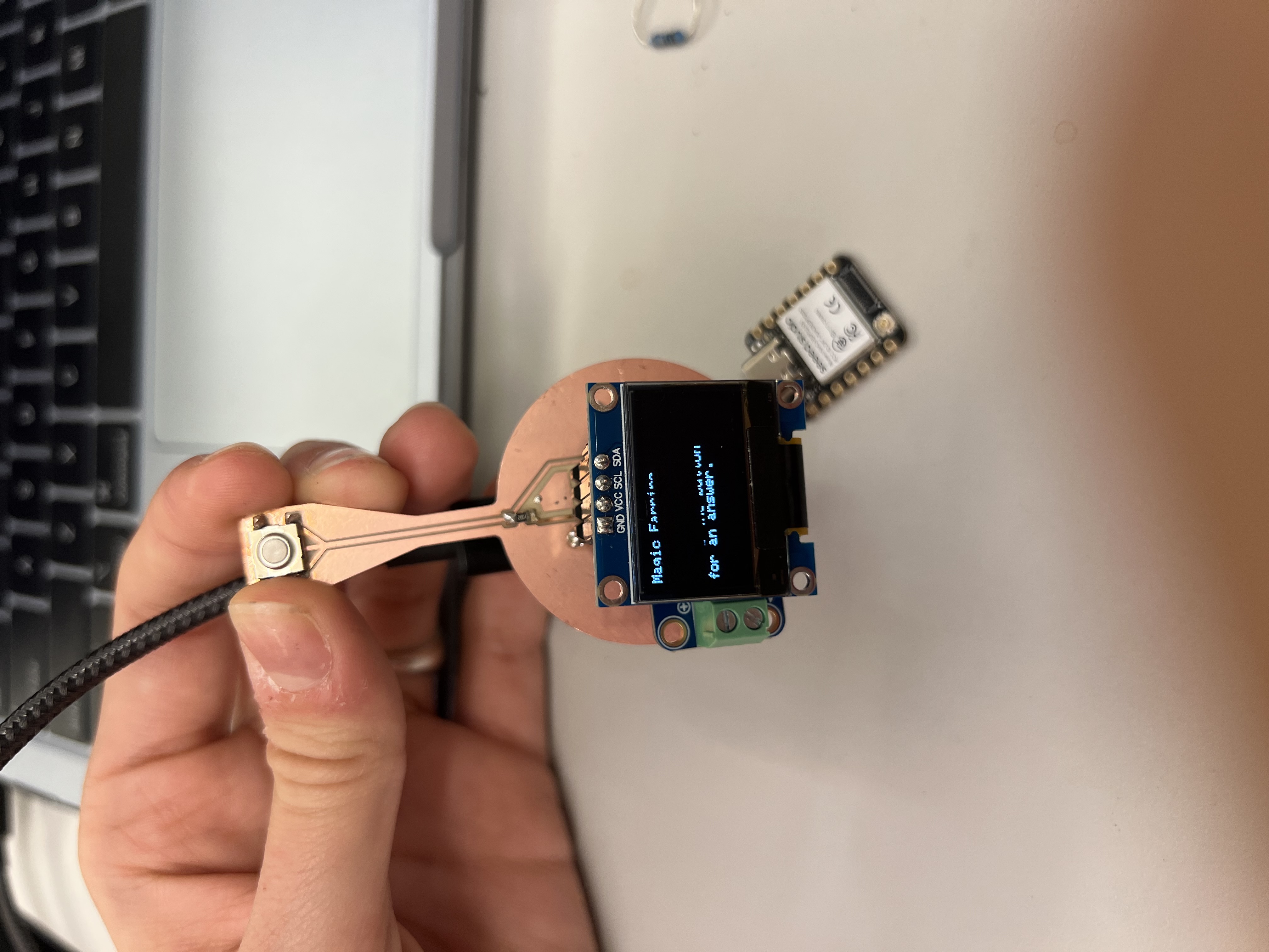
Here is the Magic Eight Ball behavior running without a final enclosure.
Getting the Speaker to Work (and Not Burn)
The most time-consuming part was achieving reliable audio output. I worked closely with Anthony to debug the audio chain: configuration, amplifier behavior, power delivery, and the physical speaker.
Early symptoms were inconsistent: faint audio, distortion, or nothing. It initially looked like a firmware problem, but the root causes were mostly physical.
At one point, I tried to up-cycle a pair of earphones from a Delta flight as a source of tiny speakers.
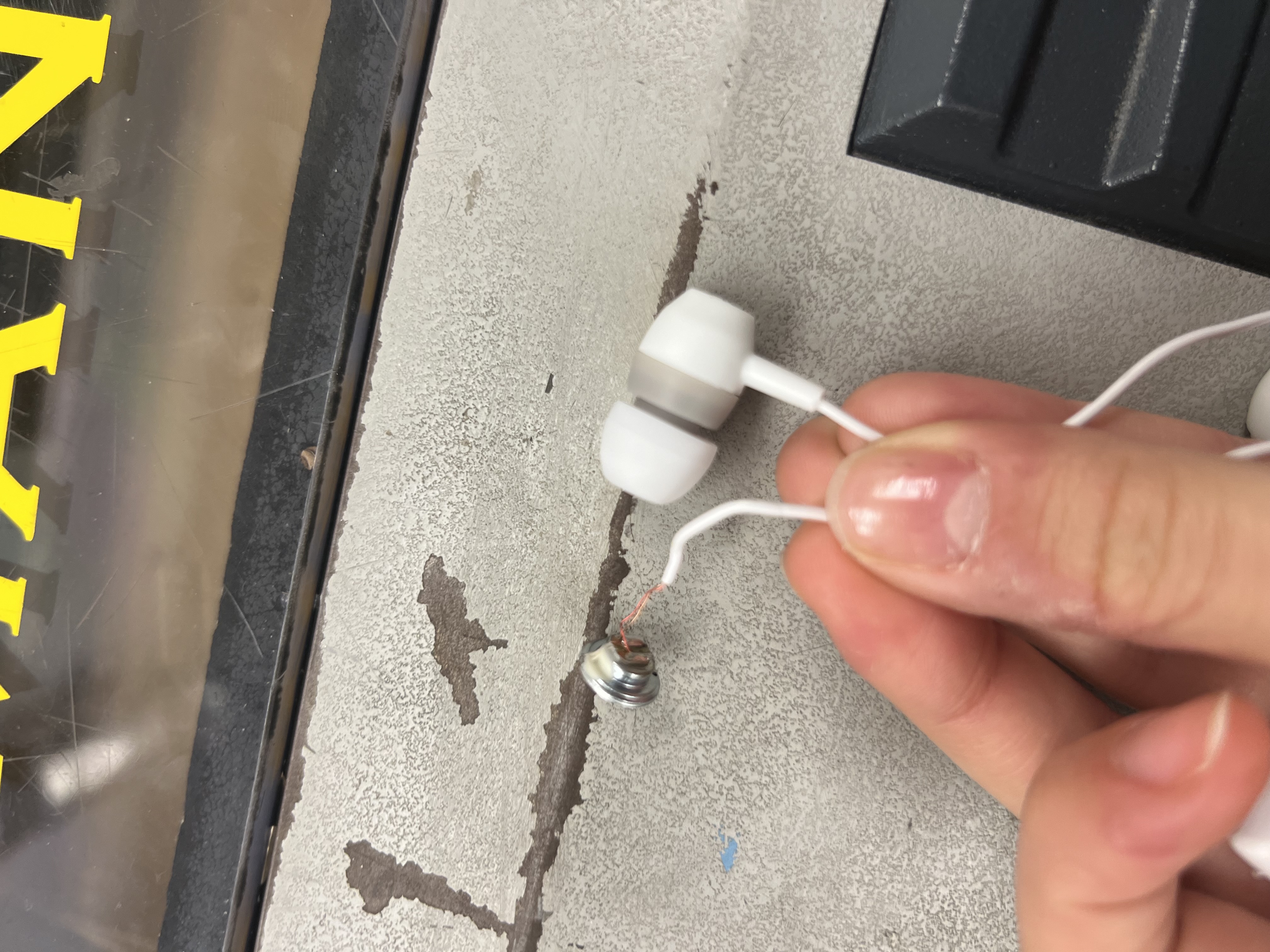
This was a dead end. With Anthony’s help, we identified these earphones were piezo-based, not conventional dynamic speakers, making them incompatible with my amplifier setup.
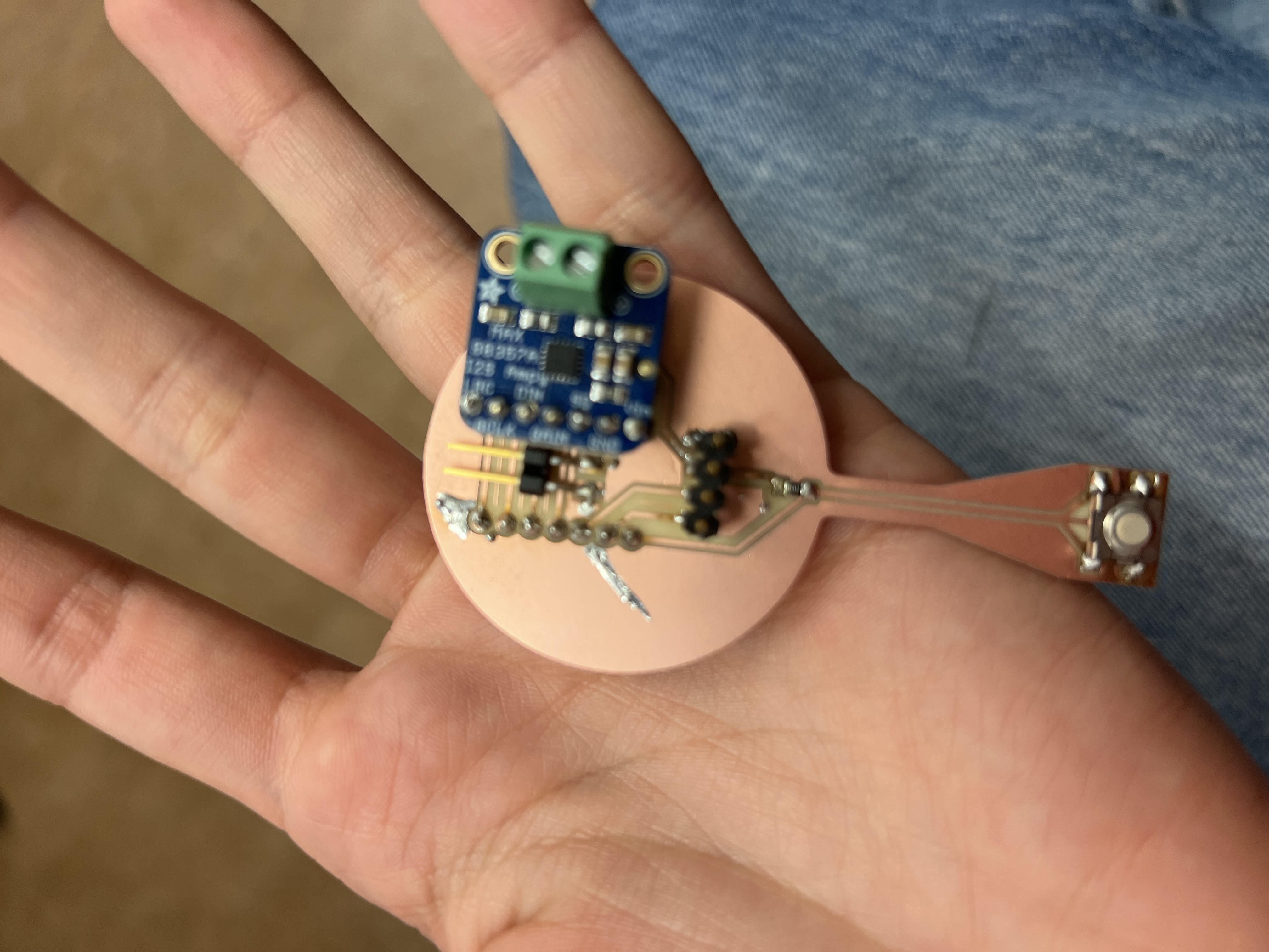
Anthony also helped identify a subtle but critical issue: the double-sided PCB was shorting in places I hadn’t anticipated. Tight clearances and through-hole components made it easy for copper regions to unintentionally connect.


To resolve shorts, I physically cut isolation trenches into the PCB to separate copper regions. This transformed the problem from a mysterious audio bug into a solvable mechanical fix. Once isolated, the amplifier behaved predictably — and the speaker stopped burning.
Double-sided boards dramatically increase failure modes. When space is tight, electrical isolation becomes a mechanical problem too.
By the end of this debugging cycle, audio output was stable enough to move forward. More importantly, it clarified how tightly coupled PCB layout, power integrity, and mechanical assembly are — especially at wearable scale.
Enclosure Experiments: From Solid to Skeletal
In parallel with electronics debugging, I explored ways to physically house the Magic Earring. This quickly became a weight-versus-sturdiness problem: anything that felt “jewelry-like” had to be light enough to wear, but anything “electronics-safe” had to protect the PCB and wiring from stress and movement.
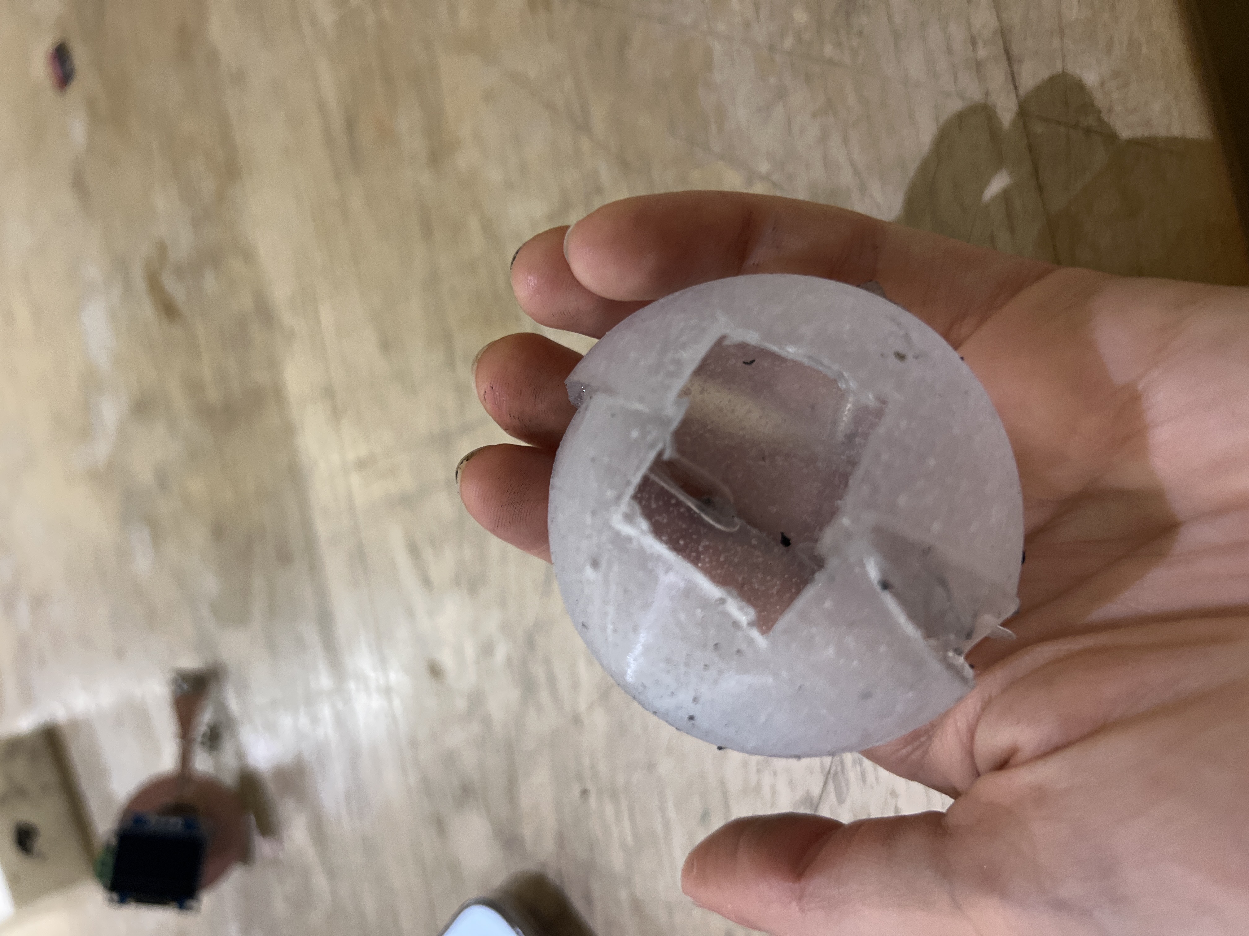
Because the device function is a Magic Eight Ball, I kept returning to a literal form factor: a crystal ball. I liked the metaphor, and also the aesthetic of being able to see through the enclosure to the guts.
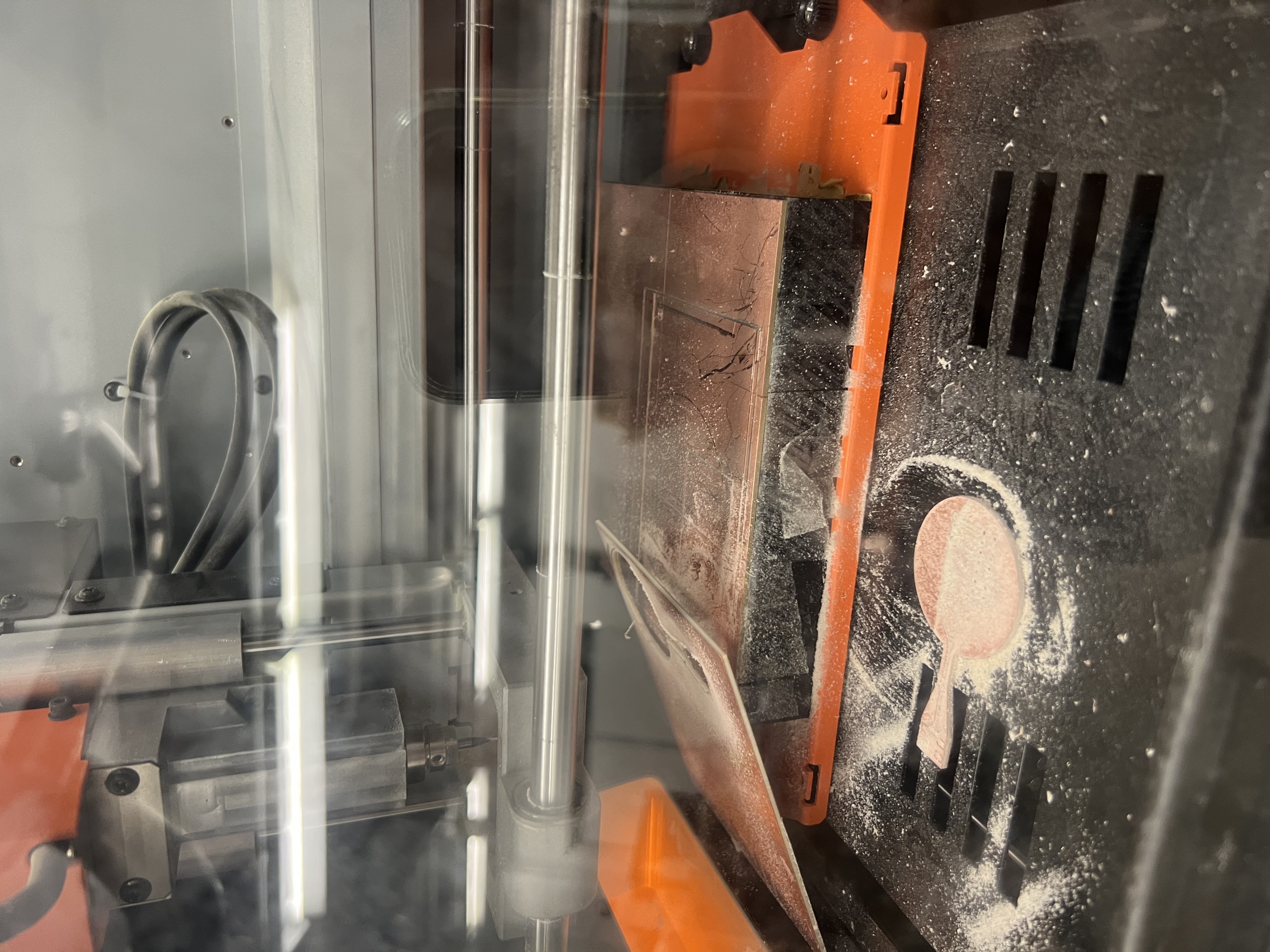
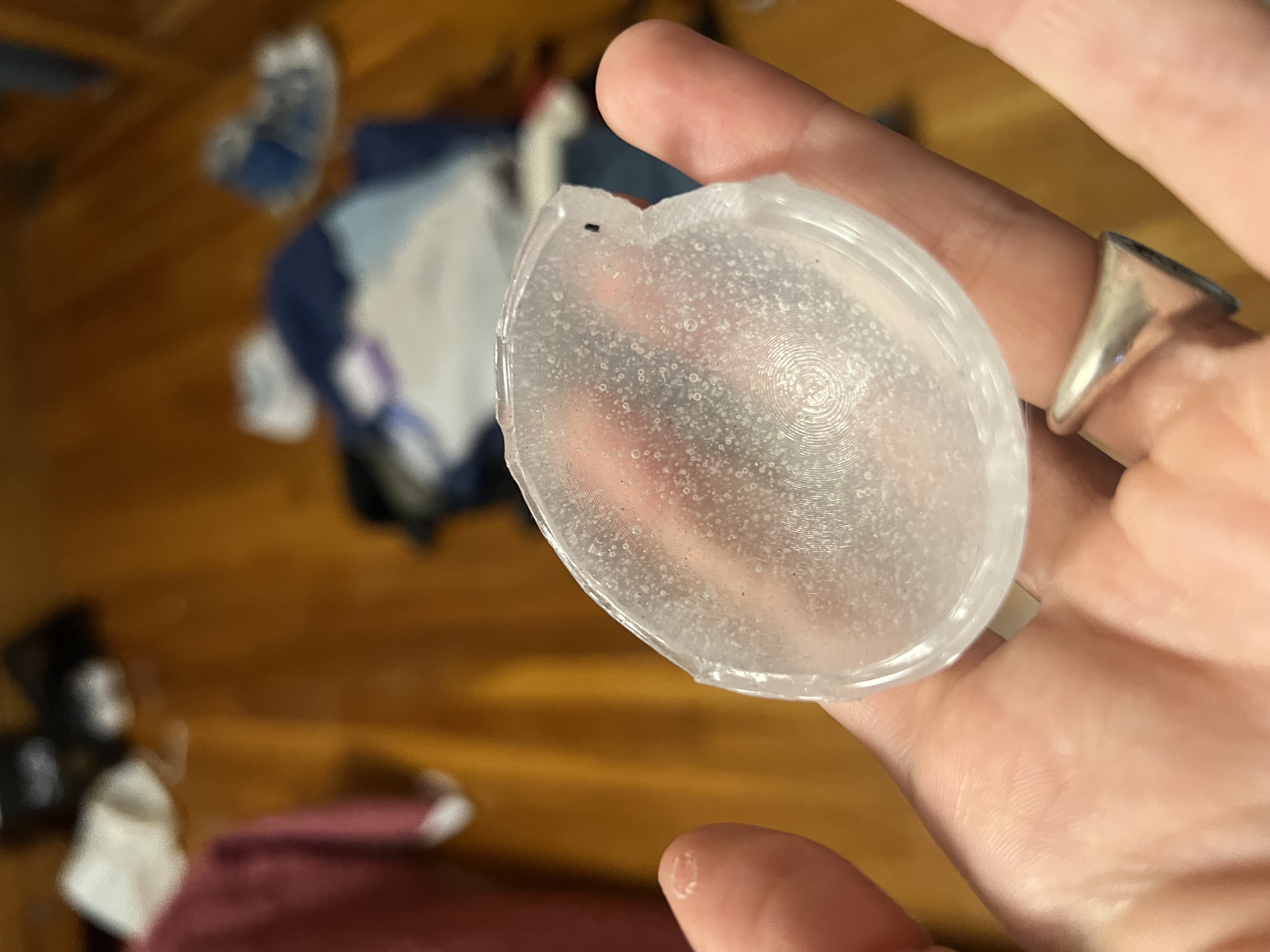
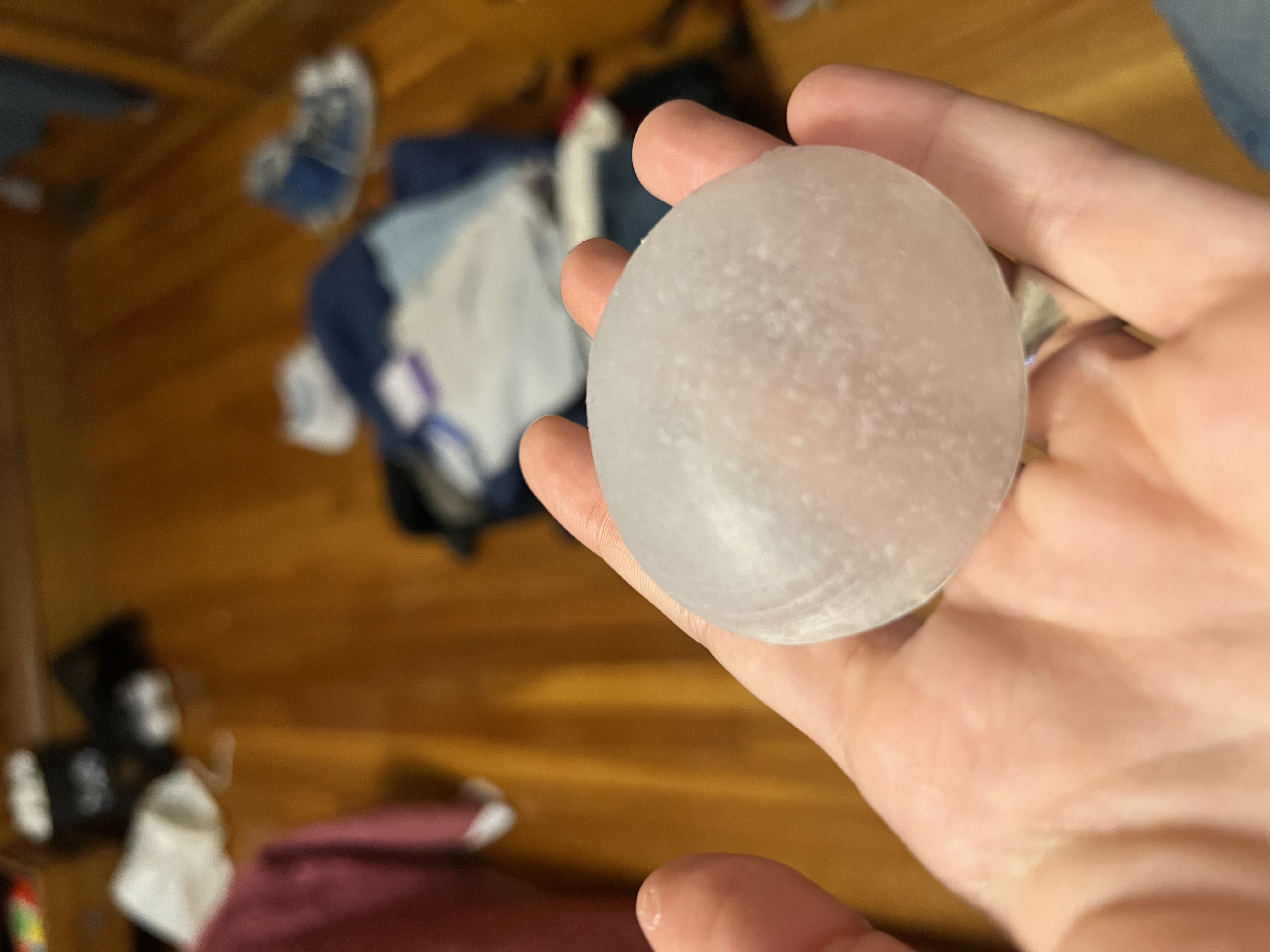
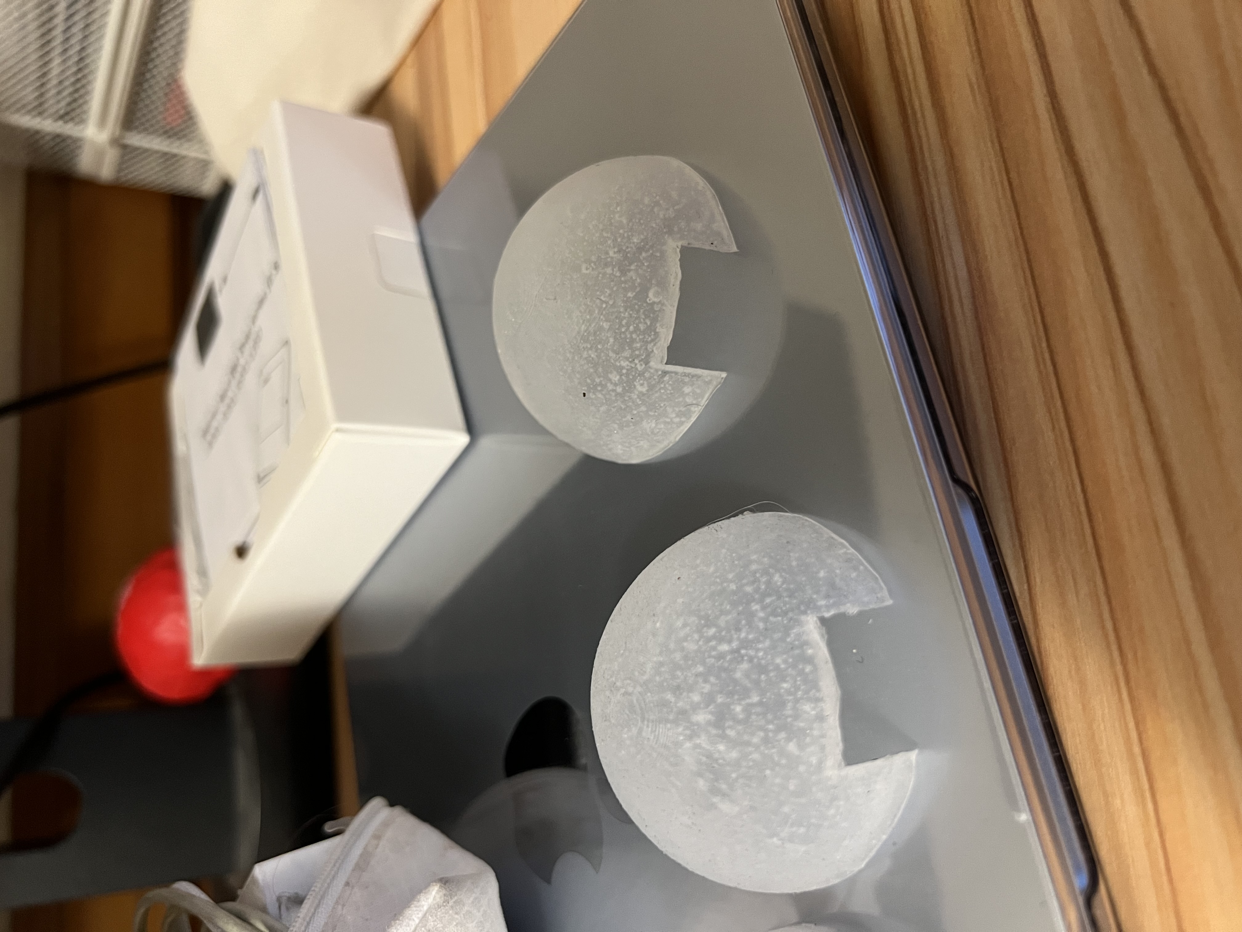
Molding & Casting (promising, but not quite the object)
I explored molding and casting to achieve a smooth, jewelry-like finish (ideally translucent). The results looked promising on the table, but repeatedly failed wearable constraints: too heavy, not sturdy in the right places, or slow to iterate as dimensions changed.


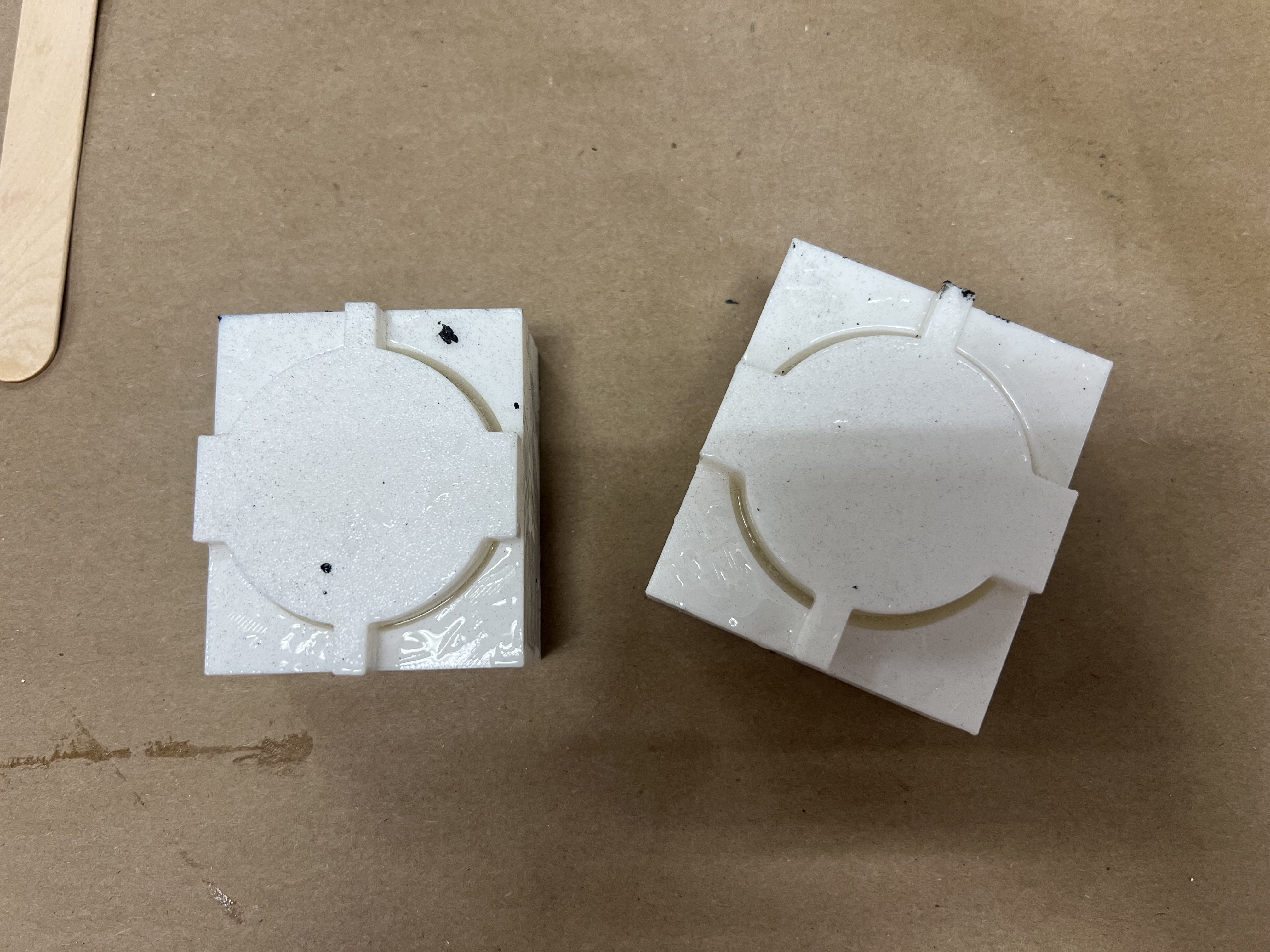

I filmed myself taking the mold out, but it turned out to be slow-motion and I wasn’t able to compress it under the upload limit. I’ll have to leave the mold “unboxing” to the reader’s imagination.
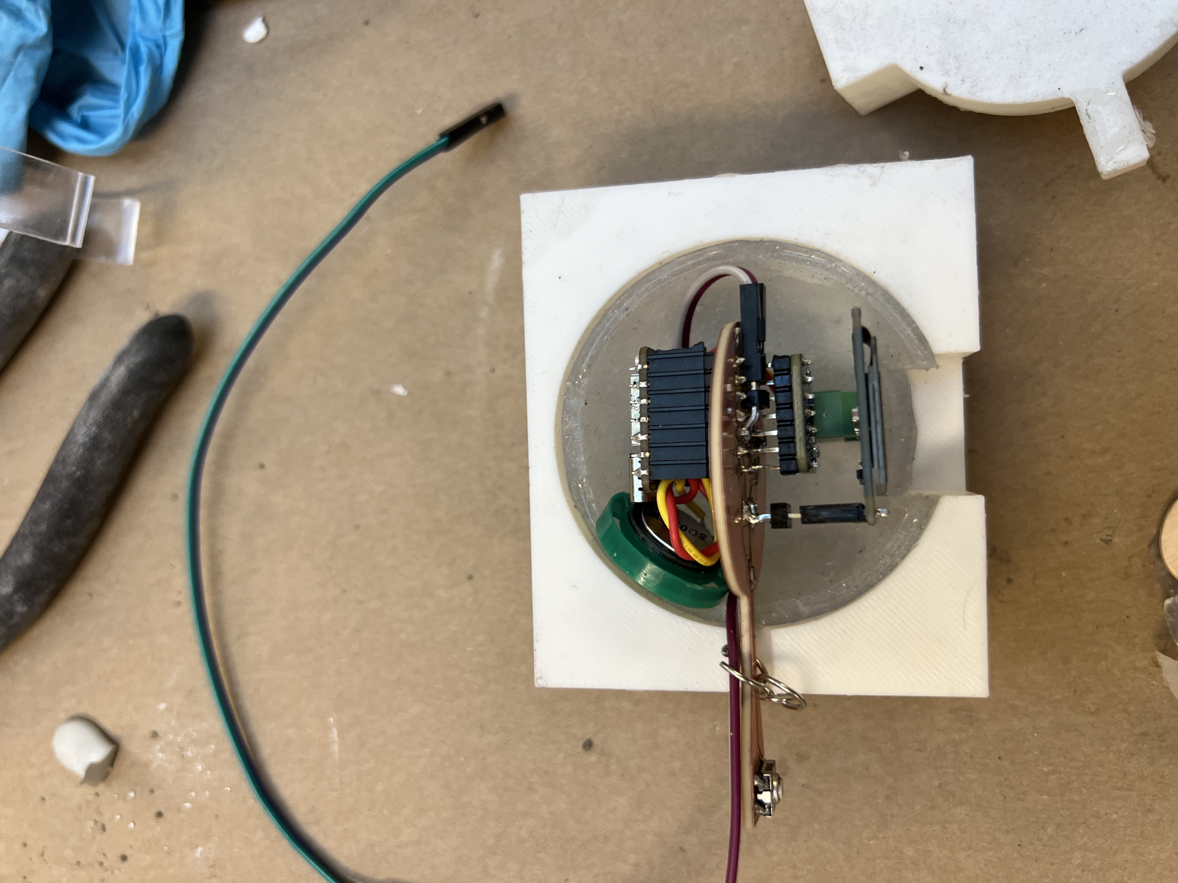
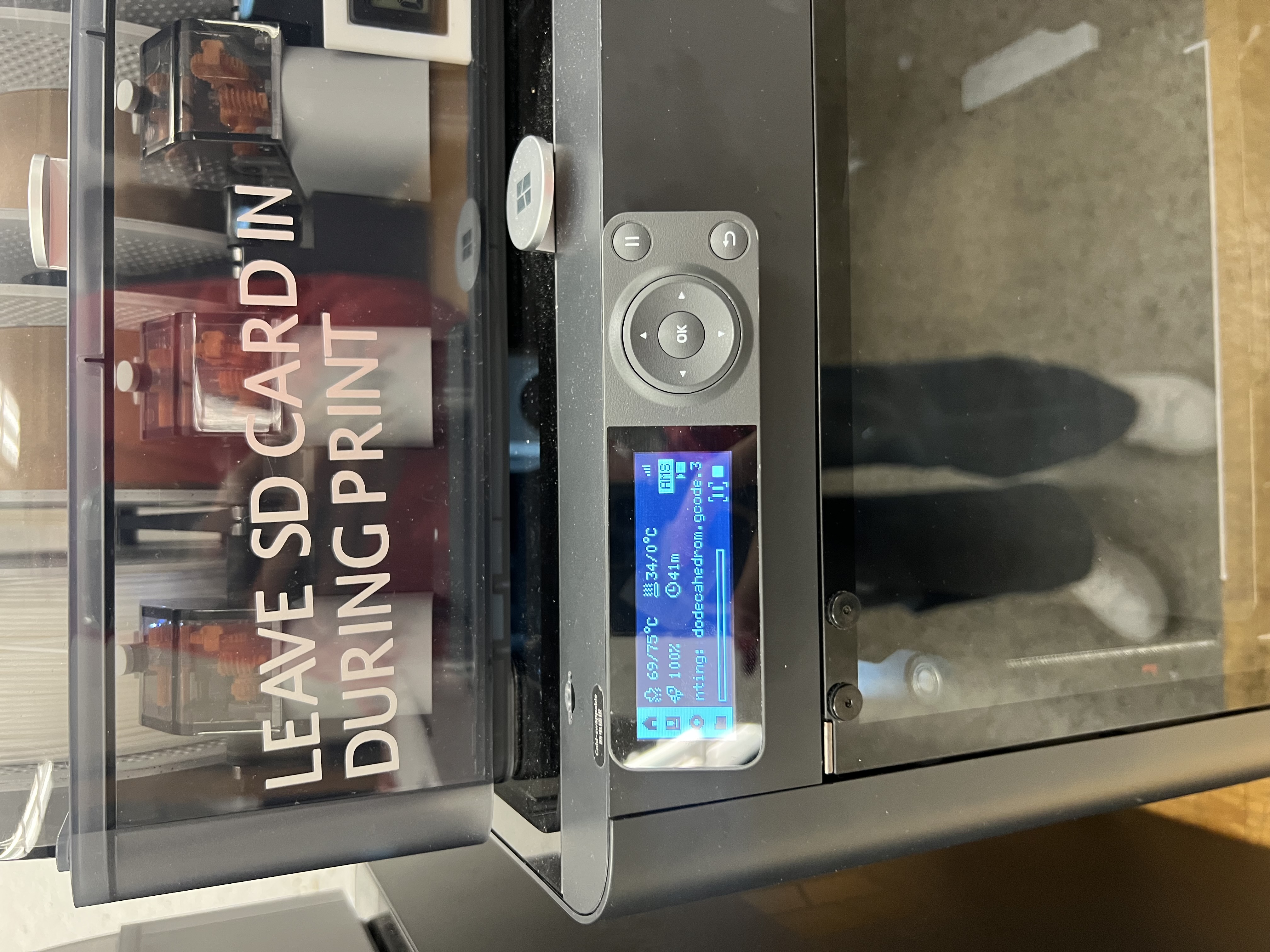
Pivot to a dodecahedron skeleton
After the cast experiments, I pivoted toward a dodecahedron skeleton enclosure: a lightweight open frame that holds the electronics without fully enclosing them. It reduced weight, improved access for debugging, and leaned into the “see the guts” aesthetic.
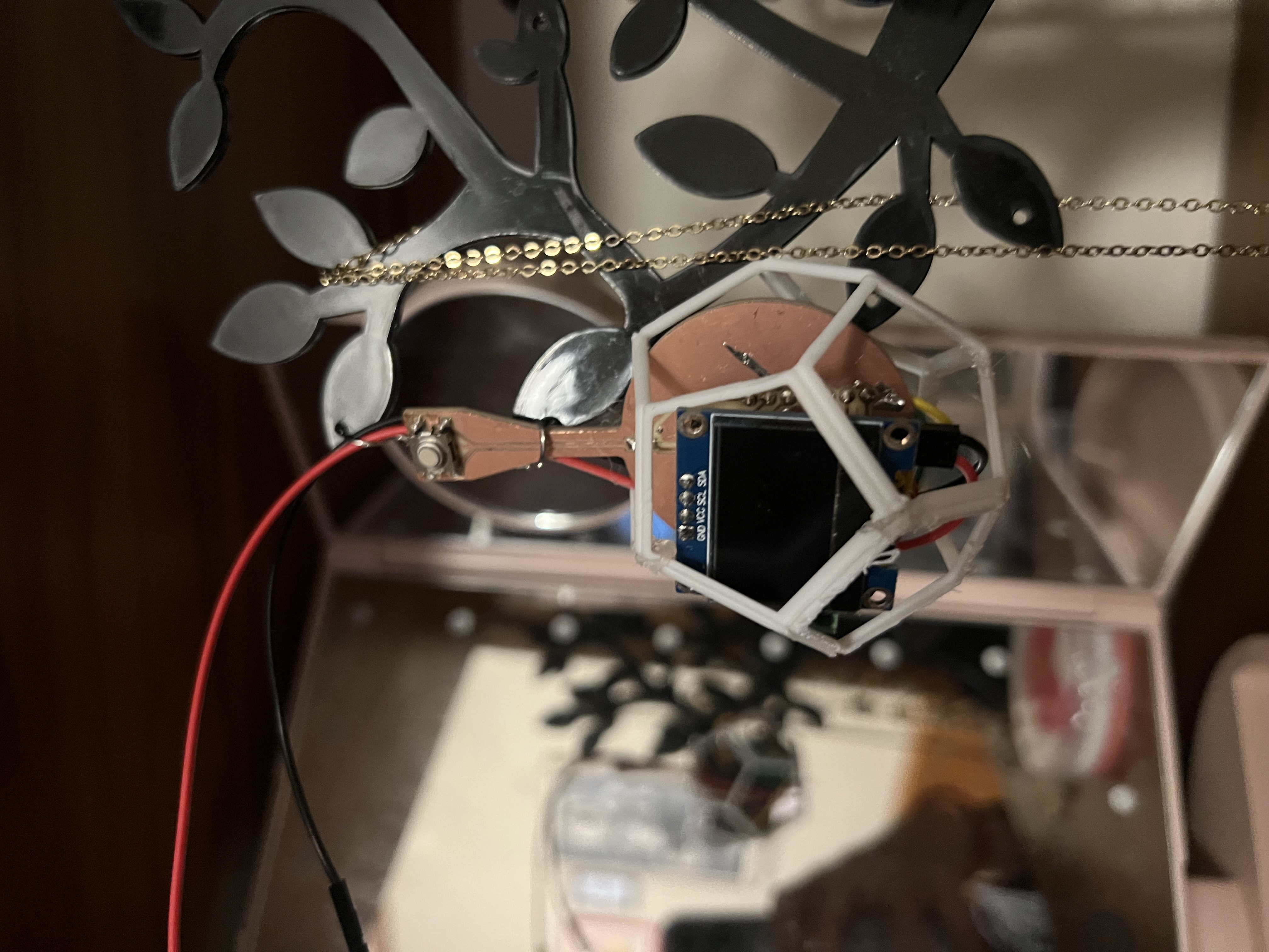

What It Does
- Advertises as a BLE device (
AudioCharm) and accepts a one-byte command. - Chooses a random Magic Eight Ball response on the ESP32-S3.
- Displays the response locally (OLED) and returns it to the client via BLE notifications.
- Outputs audio through an amplifier + speaker (test tones / short clips for v1).
Who’s Done What Beforehand
- Nova Audio Earrings — precedent for jewelry as a functional audio wearable.
- ESP32 BLE GATT examples — reference patterns for services/characteristics and WRITE + NOTIFY behavior.
- Web Bluetooth examples — reference patterns for browser connect/write/notify flows.
- Wearable enclosure inspirations — transparent / “electronics-as-object” aesthetics.
Sources Used
- Arduino IDE + Espressif ESP32 core (board support, USB-CDC/serial workflows).
- BLE tooling: LightBlue for testing discovery, services/characteristics, writes, and notifications.
- OLED libraries: Adafruit_GFX + Adafruit_SSD1306.
- KiCad + MODs workflow for PCB milling and fabrication outputs.
- Energy harvesting background reading (links included in the kinetic charging section above).
What I Designed
- Electronics: custom ESP32-S3 PCB revision integrating OLED + button + audio path constraints.
- Firmware: BLE service/characteristic + one-byte command protocol + RNG-based response selection.
- Interface: Web Bluetooth pages to connect, write commands, and receive notifications.
- Mechanical: enclosure iterations (mold-based shells + dodecahedron skeleton packaging).
- System integration: wiring, mounting strategy, and packaging tradeoffs for wearable constraints.
Materials, Components, Sources, and Cost
| Item | Qty | Source | Unit Cost | Total | Notes |
|---|---|---|---|---|---|
| XIAO ESP32-S3 module | 1 | Seeed / lab stock | $7.49 | $7.49 | Core BLE + control |
| OLED SSD1306 (I2C) | 1 | Lab stock | $2.80 | $2.80 | Local text output |
| Amplifier module / breakout | 1 | Lab stock | $5.95 | $5.95 | Audio output stage |
| Speaker / driver | 1 | Lab stock | $0.83 | $0.83 | Final working speaker (not the piezo earbud) |
| Button / switch | 1 | Lab stock | $0.92 | $0.92 | Local trigger |
| Battery / power source | 1 | Lab stock | $6.50 (est.) | $6.50 | Estimated from comparable LiPo batteries |
| PCB copper-clad + consumables | 1+ | Shop stock | $5.00 (est.) | $5.00 | FR-1 board share, bits, tape, solder, multiple milling iterations |
| 3D printing material | 1 | PLA / resin | $1.50 (est.) | $1.50 | Dodecahedron skeleton enclosure (material-only) |
| Silicone + casting materials | — | Shop stock | $8.00 (est.) | $8.00 | Mold and cast experiments (shared materials) |
| Total (estimated) | $38.99 | ||||
Items with fixed prices were taken directly from the HTMAA lab inventory where available. Remaining costs are estimates based on comparable retail components and proportional material usage. Batteries were estimated using typical prices for small LiPo cells. PCB costs reflect a fraction of copper-clad board, milling bits, tape, solder, and repeated fabrication attempts rather than the cost of a full sheet or tool. 3D printing and casting materials were estimated from the approximate volume of material used across successful and failed iterations. The earring hook was not purchased and is therefore listed at zero cost.
What Was Made vs. Bought
Made
- Custom PCB (KiCad design → in-house milling → assembly and rework).
- Enclosure iterations (3D printed skeleton + mold/cast experiments).
- Firmware + Web Bluetooth application code.
Bought / Stock
- ESP32-S3 module, OLED module, amplifier module, speaker/driver, button, wiring, adhesives/finishing consumables.
Tools and Processes Used
- 2D/3D design: Fusion 360 (CAD), KiCad (schematic + PCB), SVG workflows where applicable.
- Subtractive: PCB milling (MODs toolpaths), manual isolation cuts to fix shorts.
- Additive: 3D printing for enclosure iterations and structural prototypes.
- Molding/casting: silicone mold-making and cast experiments.
- Electronics: soldering, rework, continuity testing.
- Programming: Arduino IDE, ESP32 BLE, Web Bluetooth (HTML/JS).
What Worked and What Didn’t
Questions answered
- Can an ESP32 wearable-scale node reliably receive a command and return data over BLE? Yes.
- Can the response be surfaced locally and remotely (OLED + notifications)? Yes.
- Can audio output be integrated on a dense wearable board? Yes, but only after fixing shorts and selecting the right speaker type.
- Can the object survive motion (“shake test”)? Not yet.
Worked
- BLE GATT service/characteristic and one-byte command protocol.
- OLED output for immediate feedback.
- Web Bluetooth interface (Chrome) plus notifications.
Didn’t / pain points
- Piezo “Delta earbud” speakers were incompatible with the amplifier setup.
- Double-sided PCB shorts created failures that initially looked like software bugs.
- Packaging is not mechanically constrained enough for real motion yet.
Evaluation
- Functional demo loop: connect → send command → see OLED text → receive browser notification → hear audio output.
- Reliability: repeat command cycles without crashes or disconnects (bench-tested).
- Wearability: comfort/weight checks and instructor “shake test” feedback (currently fails; improvements listed below).
Implications
This project reframed “wearable electronics” as a packaging-first problem: small form factors force electrical, mechanical, and interaction decisions to be made together. The Magic Earring prototype demonstrates a full loop from user interface → network command → embedded logic → local + remote feedback, with a clear roadmap to become robust enough for real wear.
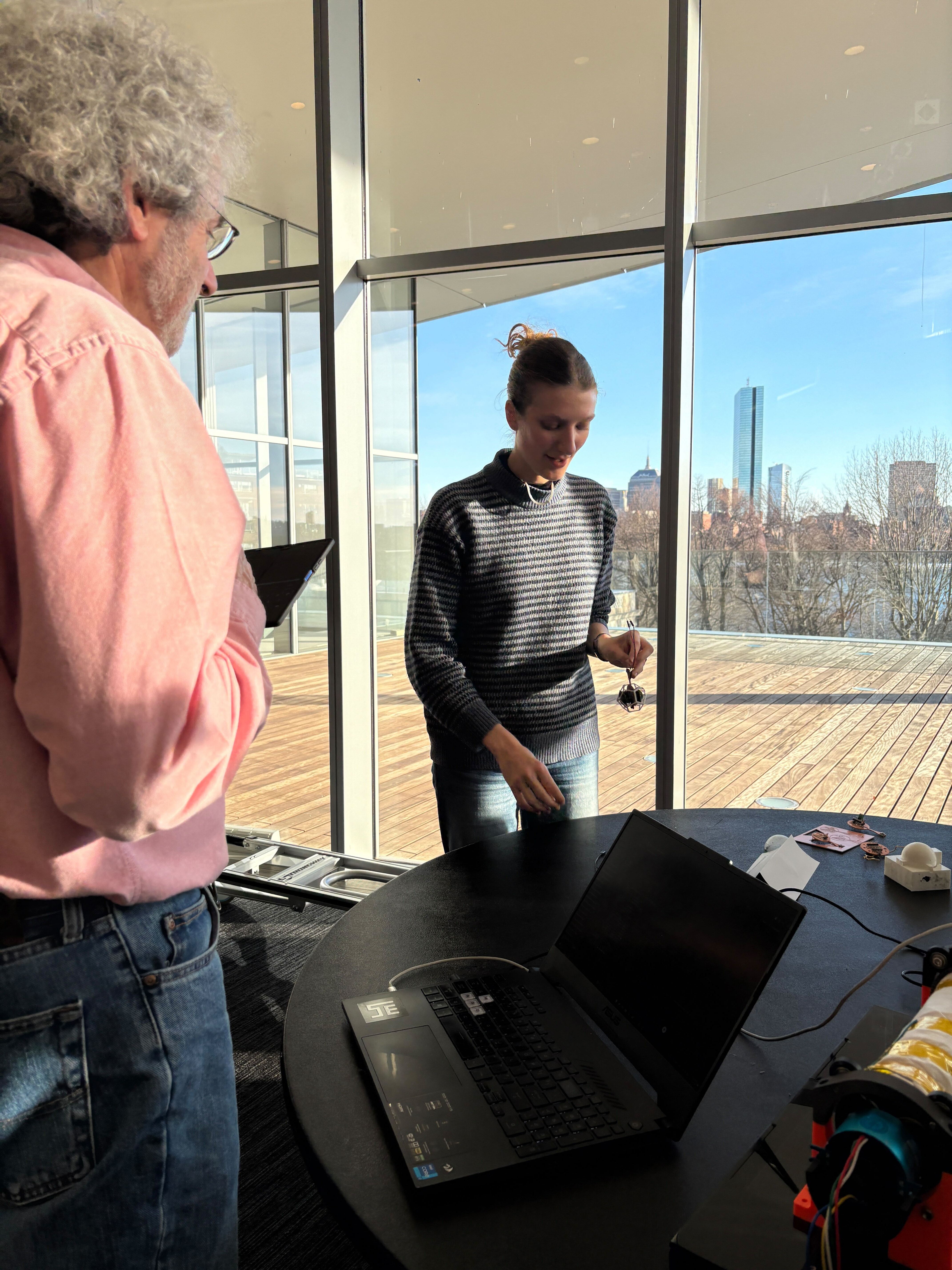
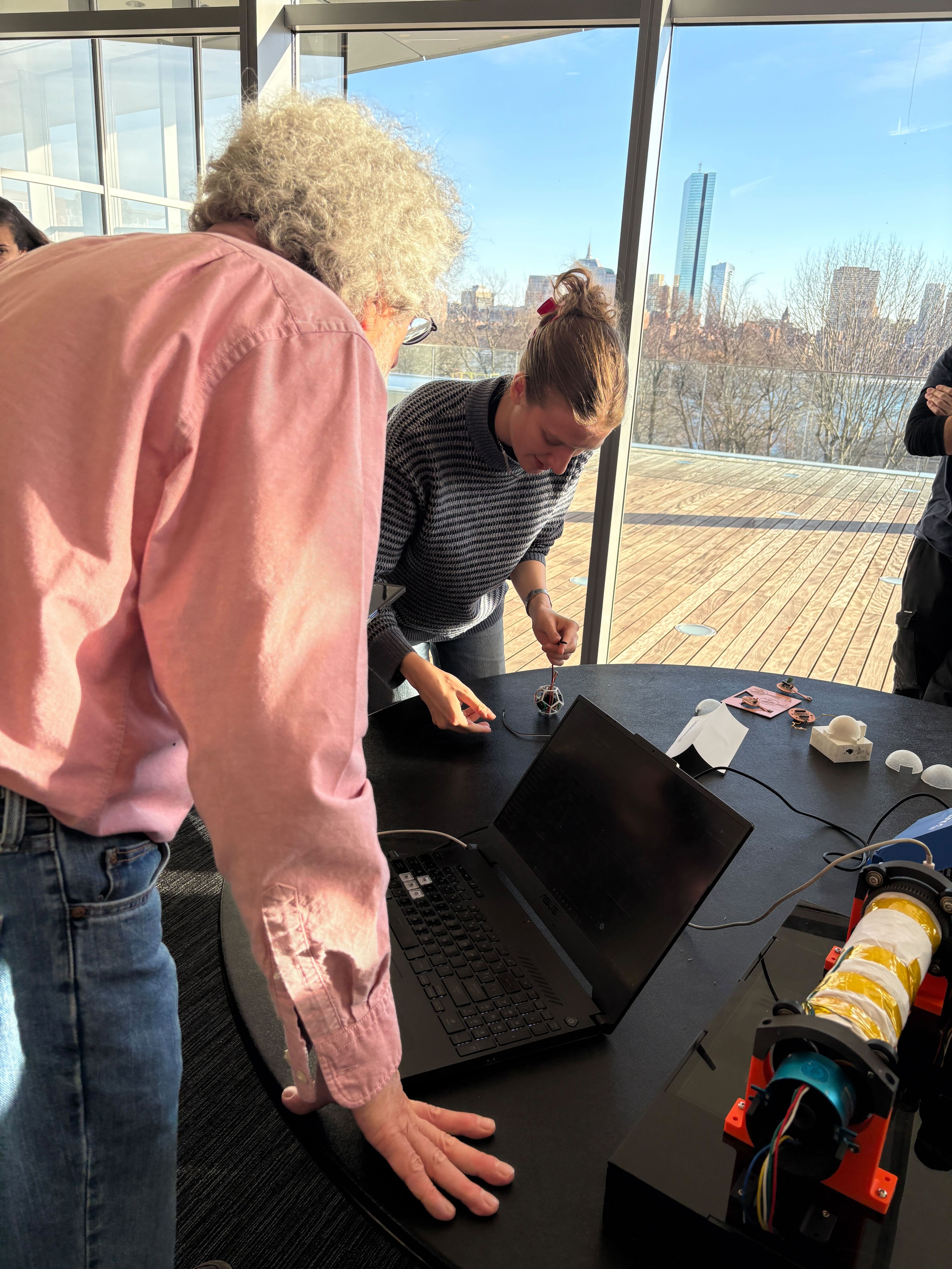
Next Steps: Passing the “Shake Test”
In the final presentation, the instructors pointed out that my current prototype would not pass the “shake test” — meaning the enclosure and internal mounting are not yet robust enough to survive real movement without wires loosening, parts shifting, or connections failing.
If I continue iterating, the goal for the next version is to design a casing and mounting strategy that makes the device mechanically reliable while remaining lightweight and wearable.
What failed (current risks)
- PCB and battery are not rigidly constrained and can shift under motion.
- Wires and solder joints experience strain without proper strain relief.
- Open frames look compelling but expose vulnerable points (connectors, leads, sharp edges).
Proposed improvements
- Internal standoffs + screws: add mounting bosses so the PCB is mechanically fixed rather than floating.
- Strain relief: route wires through channels, add tie-down points, or use short flex/connector links instead of free wires.
- Two-part enclosure with fasteners: snap-fit plus screws or threaded inserts so the enclosure clamps the internals.
- Soft lining on the body side: add a thin silicone or TPU layer to improve comfort and prevent internal shifting.
- Selective encapsulation: pot only fragile joints (not the entire device) to increase durability.
- Edge protection: cover sharp solder joints or exposed copper with conformal coating or insulation.
Reflection
These final weeks marked a transition from speculative design to physical constraints. Several assumptions — about power, audio, weight, and enclosure strategies — were invalidated by hands-on testing.
- The Magic Earring behavior is well-defined and demonstrable.
- The electronics stack is real rather than hypothetical.
- The enclosure direction now prioritizes comfort and iteration speed.
Project Media & Files
These are CAD and vector files that supported enclosure and mold iterations, linked here for reproducibility and future iteration.
- 8ball mold.stl
- mold half.stl
- sphere case.stl
- 8Ball_shape.dxf
- 8BallOutline.dxf
- 8BallPCBshape.dxf
- 8Ballwith_angles.dxf
- outline_magic8.dxf
If any of these links 404, it is usually due to filename casing (JPG vs jpg) or spacing differences between the local folder and the repository.