The HTMAA 2025 EECS Machine takes its inspiration from two terrors of tech in pop culture: the evil authoritarian Dalek of the Doctor Who universe and the ubiquitous Brain Rot of the contemporary social media era.
The BRAINROT 9000 is a Dalek-shaped autonomous robot that identifies human targets and drives towards them, automatically scrolling and passively amplifying overstimulating but vacuous "brain rot" social media content.
BRAINROT 9000 in action - autonomous target following with auto-scrolling content
My Contributions
As part of the EECS team, I focused on the vision-guided navigation system:
Flask server development: HTTP server receiving camera images from ESP32
YOLO integration: YOLO11n object detection for person tracking
Threshold control logic: Direction-based motor control using velocity differences
Velocity calculations: Worked with TA Quentin on differential drive kinematics
Other team members contributed the mechanical chassis design, Dalek exterior fabrication, auto-scroller mechanism with conductive PLA arm, and power distribution system. TA Quentin developed the ESP32 firmware for camera streaming and motor control.
For Machine Week, I developed an autonomous vision-guided robot system that combines computer vision, embedded systems, and differential drive robotics. The machine uses a YOLO (You Only Look Once) object detection model running on a Flask server to process real-time camera streams from an ESP32, compute optimal navigation commands, and control stepper motors for autonomous object tracking and following.
Complete autonomous robot system with ESP32 camera and motor control
My Individual Contributions
My primary contributions to this machine week project:
Flask Server: Designed and implemented the Flask web server (hello.py) that receives camera images, runs YOLO detection, and sends velocity commands back to the ESP32
YOLO Integration: Integrated YOLO11n model for real-time object detection with visualization
Direction-Based Control Logic: Implemented the threshold-based control in the ESP32 firmware that converts velocity differences into motor commands
Velocity-to-Steps Calculation: Worked with TA Quentin to calculate the conversion from velocity (m/s) to stepper motor steps to match Flask server output
System Architecture
The system consists of three main components working together in a closed-loop control architecture:
1. Vision Processing (Flask Server)
The Flask server runs on a host computer and serves as the computational brain of the robot. It implements several key endpoints:
/_data - Main JSON endpoint that accepts image uploads (multipart or raw JPEG) and returns detection results with ground coordinates and drive commands
/detect_image - Debug endpoint that returns annotated images with bounding boxes for visualization
/esp32_upload - Specialized endpoint for ESP32 camera stream processing
/manual - Manual control interface for testing motor responses
2. ESP32 Camera System
The ESP32-CAM module captures video frames and streams them to the Flask server over WiFi. The ESP32 runs custom Arduino code (stream.ino) that handles:
Camera initialization and configuration (resolution, JPEG quality)
HTTP POST requests to send JPEG frames to the Flask server
Receiving motor command responses
Serial communication with stepper motor drivers
Robot platform used during vision-guided testing
3. Motor Control System
The robot uses a differential-drive base with two stepper motors controlled through the ESP32. I cover the kinematics, threshold logic, and drivetrain packaging in more detail in the motor control section below.
YOLO Object Detection
Model Selection & Configuration
I chose YOLO11n (nano variant) for this application due to its excellent balance between detection accuracy and inference speed. The model runs at approximately 30-60 FPS on the host computer, enabling real-time robot control. The detector is implemented in model/detector.py with the following features:
Confidence threshold of 0.5 to filter false positives
Support for multiple object classes (person, bottle, cell phone, etc.)
Bounding box visualization with labels and confidence scores
Batch processing capability for efficiency
Detection Pipeline
The detection pipeline follows these steps:
Receive JPEG image from ESP32 camera (typically 640×480 or 800×600)
Decode JPEG to PIL Image format
Run YOLO inference to detect objects and generate bounding boxes
Extract bottom-center pixel coordinates of each detection
Transform pixel coordinates to ground-plane coordinates using homography
Compute drive commands based on object positions
Return commands to ESP32 for motor execution
Single still from the Flask testing interface showing detections, labels, and drive command output.
Direction-Based Control (Demo Implementation)
For the machine week demonstration, I implemented a simplified direction-based control system instead of full homography calibration. This approach uses the velocity difference between left and right wheels (computed by the Flask server from detection positions) to determine the robot's turning behavior.
The ESP32 firmware uses simple threshold logic to convert velocity differences into discrete motor commands:
if (v_left - v_right >= 0.15)  {
    s1 = 1;   // turn right
    s2 = 1;
}

if (v_left - v_right <= -0.15) {
    s1 = -1;  // turn left
    s2 = -1;
}

if (abs(v_left - v_right) < 0.15) {
    s1 = -1;  // go straight
    s2 = -1;
}

if (v_left == 0.0 && v_right == 0.0) {
    s1 = 0;   // stop
    s2 = 0;
}
This simplified approach proved effective for the demonstration, allowing the robot to track and follow detected objects without requiring precise distance measurements. The threshold of 0.15 m/s difference was experimentally tuned to provide smooth turning behavior.
Note: While the Flask server includes homography calibration code for potential future use with accurate spatial positioning, the demo implementation uses this simpler velocity-difference approach in the ESP32 firmware for more robust real-time performance.
Robot follow-behavior tuning and motor response testing
Motor Control & Kinematics
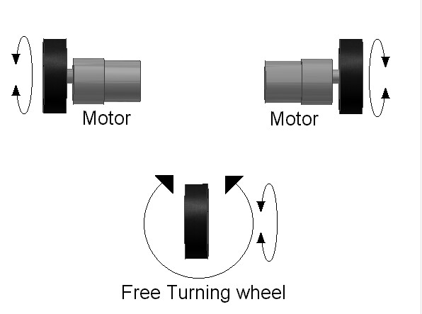
Differential Drive Kinematics
The robot uses differential drive, where independent control of left and right wheel velocities enables turning and forward motion. The key parameters:
Wheel base: 0.45 meters (45 cm) - distance between left and right wheels
Wheel circumference: 0.1 meters - used for velocity-to-steps conversion
Differential-drive turning behavior depends on the relative direction and speed of the left and right wheels.
How Drive Commands Were Interpreted
The Flask server outputs left and right wheel velocities based on the tracked target position. On the embedded side, I used the same threshold-based logic described above to convert those values into simple left, right, straight, and stop behaviors instead of trying to run a more fragile fully calibrated controller during the demo.
That simplified interpretation layer was more reliable for the live demo than the earlier precise velocity-to-steps approach I worked on with a TA, described below.
Motor Control Evolution
Originally, we used micropython and a different MCU to send UART commands for motor control, before we adopted an ESP32 based microcontroller that had bluetooth capabilities. In this original system, we controlled the robot by commanding steps according to the velocity. I contributed the threshold-based control logic and helped write the velocity-to-steps conversion:
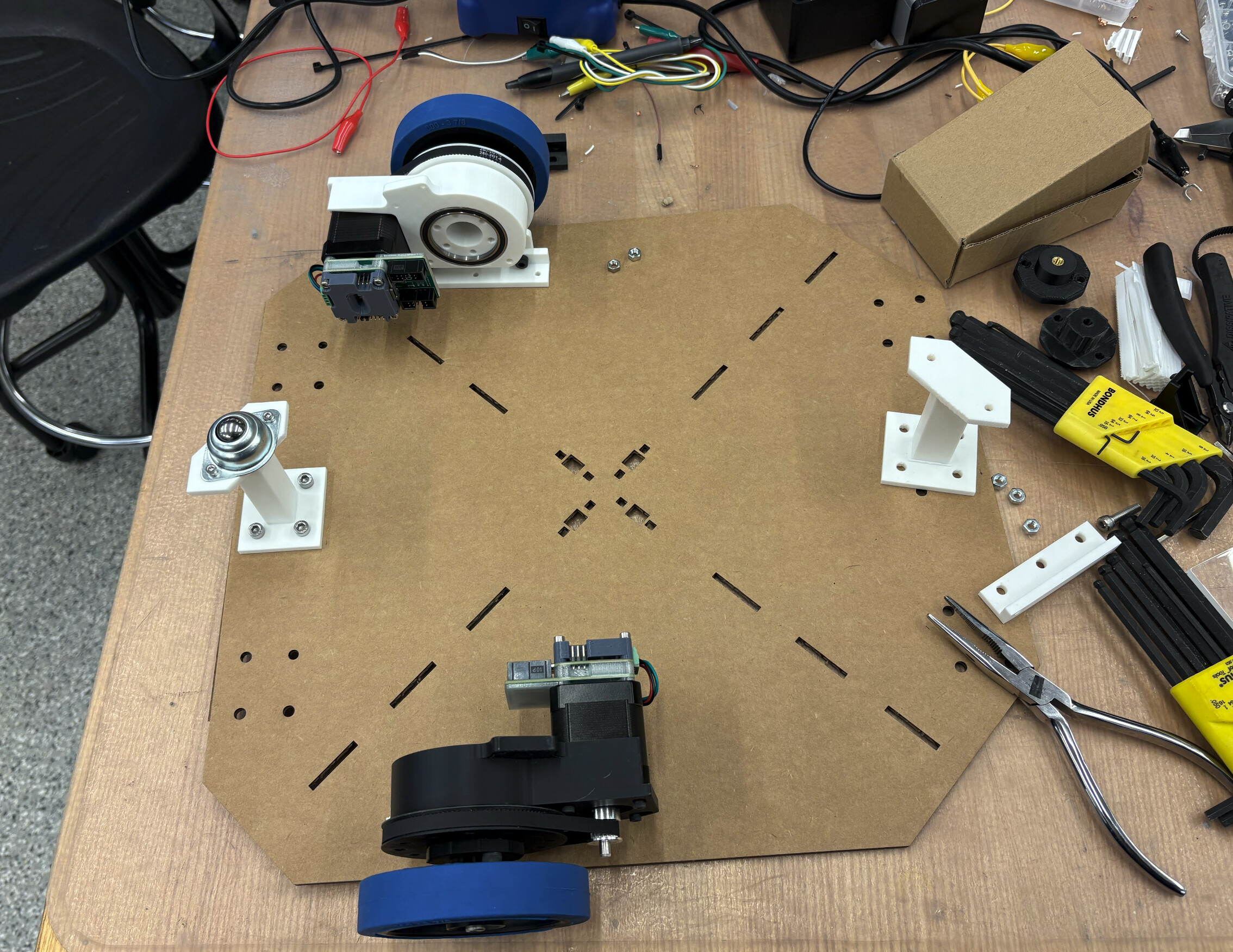
Drive base parts and wheel modules laid out during drivetrain assembly and integration.
Manual Control Interface
I also built a small web control page at /manual for testing motor responses before running the full follow behavior:
Forward: Both wheels same speed forward
Backward: Both wheels same speed backward
CW (Clockwise): Rotate in place clockwise
CCW (Counter-Clockwise): Rotate in place counter-clockwise
Rather than include another nearly identical screenshot here, I used the webcam demo video below to show this same interface in motion while testing responses.
Communication Protocol
ESP32 to Flask Server
The ESP32 sends images to the Flask server via HTTP POST requests. The image data is sent as multipart/form-data or raw JPEG bytes. Response format (JSON):
Motor commands are sent from the Flask server to the ESP32 via serial communication. The protocol is simple CSV format:
v_left,v_right\n
Example: 0.15,0.12\n commands left wheel at 0.15 m/s and right wheel at 0.12 m/s.
Demonstration Videos
Robot Following Object
This video demonstrates the robot autonomously following a detected person. The YOLO model detects the person, calculates their ground-plane position, and the robot adjusts its velocity to follow while maintaining a safe distance.
Robot autonomously following detected person
Webcam Testing - Face Detection & Motor Control
Initial testing was performed using a webcam instead of the ESP32 camera. This video shows the detection system identifying faces and computing appropriate motor commands. The annotated video displays bounding boxes and the calculated drive velocities in real-time.
Webcam testing showing face detection and motor command generation
Manual Control Testing
Before the full robot body was assembled, I used short bench tests to validate that the drivetrain responded correctly to commanded wheel motion. This clip captures one of those early motion checks on the base platform.
Early drivetrain bench test during motion validation
Technical Challenges & Solutions
Challenge 1: WiFi Latency
Problem: Initial tests showed 200-400ms latency between image capture and motor command execution, causing jerky motion and overshooting.
Solution: Optimized the pipeline by:
Reducing JPEG quality from 80% to 60% (smaller file size, faster transfer)
Lowering camera resolution from 800×600 to 640×480
Implementing frame skipping: process every 3rd frame instead of every frame
Using connection pooling in the ESP32 HTTP client
Result: Reduced latency to 80-120ms, acceptable for tracking slow-moving objects.
Challenge 2: Homography Accuracy
Problem: Initial homography calibration showed errors of 10-15cm at distances beyond 1 meter due to lens distortion and calibration point placement.
Solution: Improved calibration by:
Increasing number of calibration points from 4 to 5
Spreading points across the full camera field of view
Using high-contrast markers for precise pixel identification
Validating with test points at multiple distances
Result: Reduced error to 3-5cm at 1 meter distance.
Challenge 3: Motor Stalling on Sharp Turns
Problem: Motors would stall when the pure-pursuit controller commanded very sharp turns (small turn radius).
Solution: Implemented acceleration limiting:
Maximum velocity change per update limited to 0.05 m/s
Minimum turn radius clamped to 0.3m (prevents in-place rotation at high speed)
Added velocity ramping in ESP32 firmware
Result: Smooth turns without stalling, though sacrificing some agility.
Challenge 4: ESP32 Migration
Problem: Migrating from Teensy to ESP32 required rewriting motor control code and dealing with ESP32's limited hardware timers.
Solution:
Used ESP32's hardware timer API for pulse generation
Implemented software timer fallback for second motor
Carefully tuned interrupt priorities to avoid WiFi/serial conflicts
Added mutex protection for shared variables
Code Structure
The project consists of Python Flask server code and Arduino C++ firmware:
Python Flask Server (my work):
hello.py - Flask application with YOLO detection and motor command endpoints
model/detector.py - YOLO detection wrapper
drive_controller.py - Drive calculations (includes homography code for future use)
ESP32 Firmware (TA Quentin, with my threshold logic):
connected_motor_control.ino - Camera streaming and motor control with threshold-based decisions
📥 Download Source Code
The complete source code for the YOLO-Flask robot system:
After discussing the machine with Anthony, I gathered and filtered references by subsystem so each part of the build had a clearer set of precedents. These links informed how we thought about packaging the scroller, drive base, sensing stack, and outer shell.
Machine Week team with the finished BRAINROT 9000.
Subsystem A: Scroller Arm + Phone Holder
These references helped frame how to mount, move, and support the phone as an active payload.
This was the subsystem closest to my contribution area, so I collected references spanning manual teleoperation, FPV streaming, line following, object tracking, and embedded AI deployment.
These references helped the team think about wheel configuration, drivetrain packaging, and what kinds of motion were realistic for a Dalek-inspired robot.
For the internal column and base proportions, we reused many of the shell references above because they were the best source for overall dimensions, internal layout cues, and stacking order.