Sensing Module Part 2: Accelerometer
I programmed the ESP32 to read acceleration data from the ADXL343 using the Adafruit library:
#include <Adafruit_ADXL343.h>

Adafruit_ADXL343 accel = Adafruit_ADXL343(12345);

void setup() {
  Serial.begin(115200);

  if(!accel.begin()) {
    Serial.println(\"No ADXL343 detected!\");
    while(1);
  }

  // Set range to +/-4g for water bottle movements
  accel.setRange(ADXL343_RANGE_4_G);

  // Set data rate to 100Hz
  accel.setDataRate(ADXL343_DATARATE_100_HZ);
}

void loop() {
  sensors_event_t event;
  accel.getEvent(&event);

  Serial.print(\"X: \"); Serial.print(event.acceleration.x);
  Serial.print(\" Y: \"); Serial.print(event.acceleration.y);
  Serial.print(\" Z: \"); Serial.println(event.acceleration.z);

  delay(100);
}
Testing & Results
I tested the accelerometer by tilting and moving the sensor board in different orientations:
- \u2705 Flat/stable detection: Z-axis reads ~9.8 m/s\u00b2 (1g)
- \u2705 Tilt detection: X and Y axes show angle changes
- \u2705 Motion detection: Rapid changes indicate movement
- \u2705 Noise level: ~\u00b10.1 m/s\u00b2 when stationary
\u2728 Use Case: Stable Measurement Detection
\n
\n For the hydration monitor, the accelerometer determines when the water bottle is:\n
\n
\n - Upright: Z-axis dominant, X/Y near zero
\n - Stationary: Low variance in readings over 1 second
\n - Ready for measurement: Both conditions met for 2+ seconds
\n
\n
\n Only when these conditions are satisfied does the system take a valid weight reading from the load cell, preventing false readings from movement or tilted positions.\n
\n
Group Assignment: Probing Analog & Digital Signals
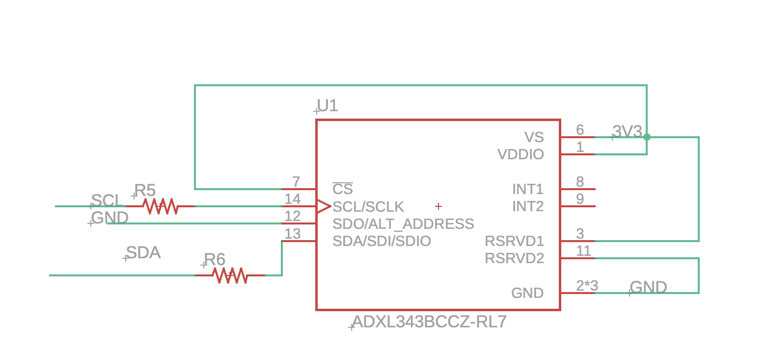
\n For the group assignment, we used an oscilloscope to probe the I2C signals between the ESP32 and ADXL343:\n
\n
\n - SCL (clock): 100kHz square wave during data transmission
\n - SDA (data): Digital pulses representing I2C address and data bytes
\n - Voltage levels: Confirmed 3.3V logic levels with clean transitions
\n - Pull-up function: Verified 4.7k\u03a9 resistors create proper idle high state
\n
\n We also measured the analog voltage on the ADXL343's power pin to ensure stable 3.3V supply during operation.\n
Connection to Final Project
\n While the accelerometer was designed for this week's assignment, I ultimately used a load cell with HX711 amplifier for the final project instead. The load cell provides more direct weight measurement without needing complex tilt compensation.\n
\n
\n However, the skills from this week\u2014I2C communication, sensor calibration, and signal processing\u2014directly transferred to working with the HX711 and other sensors in my hydration monitoring system.\n
ADXL343 Datasheet