Introduction
This week we learned about output devices. Output devices are devices that take in data from a microcontroller and convert it into a form that humans can perceive, such as sound, light, or movement. Some common output devices include speakers, LEDs, and motors.
Project Context: Plant Nanny Inspiration
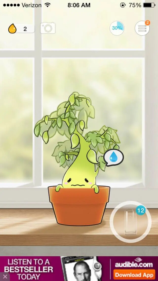
My water bottle project was inspired by Plant Nanny, a hydration tracking app where you water a cute plant character as you drink water throughout the day. However, I found the manual logging frustrating—it was too easy to cheat by logging fake water intake just to keep the plant alive.
My solution: Create a physical device that automatically tracks water consumption using sensors, eliminating the need for manual input while maintaining the engaging visual feedback of a cute character.
Output Device for Stationary Plant Mascot
I decided to use a TFT display as the primary output device. Additionally, I plan to include a few RGB LEDs that can change color based on the user's hydration level throughout the day. For example, the LEDs could glow green when the user is on track with their water intake and shift to yellow or red if they fall behind their goals. This visual feedback will help users stay aware of their hydration habits in a fun and engaging way. Overall, the combination of sound and light output devices will create an interactive experience that motivates users to drink more water regularly.
Output Device for Mobile water bottle attachment
For the mobile water bottle attachment, I plan to use a small speaker to provide auditory feedback. The speaker can play cheerful sounds or short tunes when the user takes a sip of water, reinforcing positive behavior. . In previous weeks I wanted to use a distance sensor but I realized that that is not practical. As a load sensor, the device would be located underneath my water bottle to measure the weight and estimate the amount of water consumed.
but how do I visualize the weight measurement?
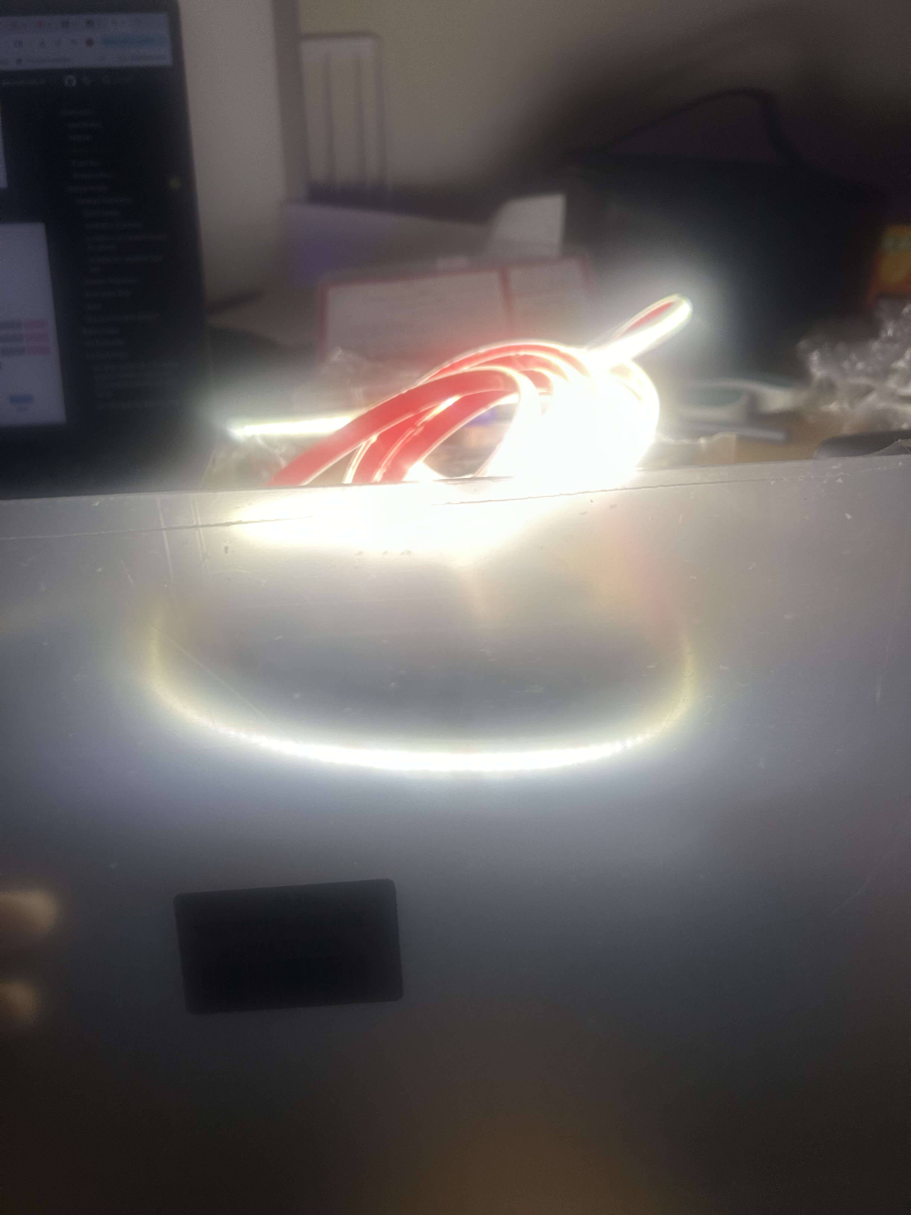
I decided on a ring of LED strip lights around the base of the water bottle, above the attachment. When a load was being measured, the LEDs would emit a warm light, which gives feedback to the user when measurements are occuring.
Making Output Devices
For this week's assignment, I designed and tested multiple output devices for my hydration monitor system. The assignment required measuring the power consumption and understanding the behavior of each output device.
Output Device 1: LED Ring for Load Cell Feedback
I tested an addressable LED ring (NeoPixel-compatible) to provide visual feedback when the load cell is taking weight measurements. The LEDs glow warm white during active sensing.

LED Ring Specifications
- Type: WS2812B addressable RGB LEDs
- Count: 16 LEDs in ring formation
- Power: ~60mA per LED at full brightness white (960mA total)
- Control: Single-wire protocol (GPIO pin)
- Voltage: 5V supply with 3.3V logic
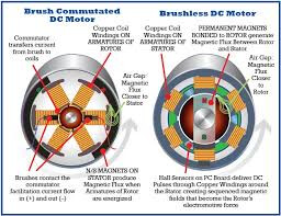
Output Device 2: Servo Motor (Tested, Not Used)
I initially explored using a servo motor to create a physical indicator, but decided the TFT display was more expressive and used less power.
Servo Testing Results
- Model: SG90 micro servo
- Power draw: ~100-200mA during movement, 10mA idle
- Control: PWM signal (50Hz, 1-2ms pulse width)
- Conclusion: Too mechanical; TFT provides better emotional expression
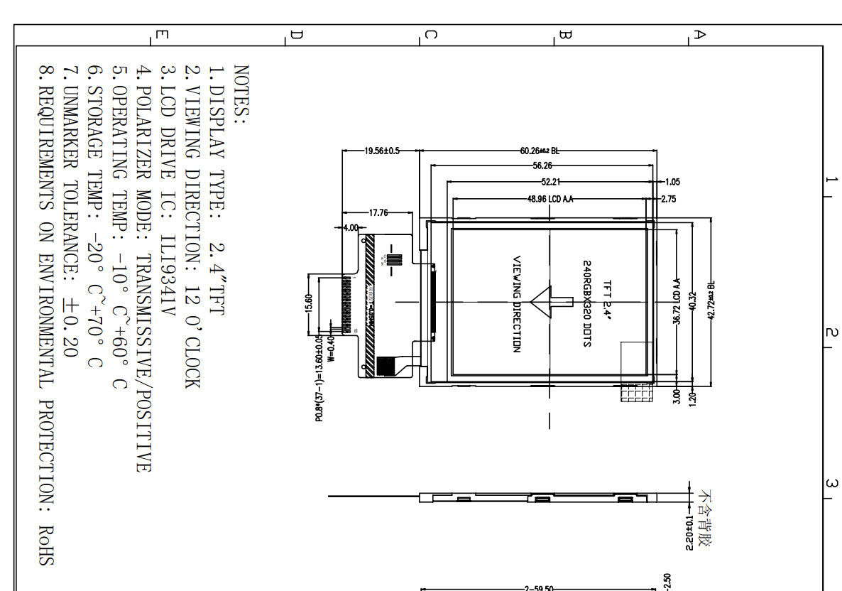
Output Device 3: ILI9341 TFT Display (Primary Choice)
For this week's assignment, I designed and fabricated a custom PCB featuring an ILI9341 TFT display as the primary output device. The display serves as the "face" of my hydration reminder robot for my final project, capable of expressing different emotions to encourage water consumption throughout the day.
The board interfaces a 2.8" 320×240 pixel TFT LCD with an ESP32-S3 microcontroller, creating an expressive robot character that responds to water bottle weight measurements received via Bluetooth Low Energy (BLE).
Board Design & Schematic
I designed the board to integrate the ILI9341 TFT display with an ESP32-S3 Xiao module. The schematic shows the complete circuit including:
- ESP32-S3 Xiao - Main microcontroller with built-in BLE
- ILI9341 TFT Display - 320×240 RGB LCD with SPI interface
- Schottky Diode - For power protection
- Decoupling Capacitors - For power supply stability
- 14-pin Header - For programming and expansion

Pin Connections
The TFT display uses the following SPI connections:
- TFT_CS: RX (GPIO3) - Chip Select
- TFT_DC: TX (GPIO0) - Data/Command
- TFT_RST: D1 (GPIO1) - Reset
- TFT_MOSI: GPIO10 - SPI Data Out
- TFT_SCLK: GPIO8 - SPI Clock
Board Fabrication
I fabricated the board using double-sided copper stock on the Roland MDX-40A mill. This was my first time working with double-sided PCBs, which required careful alignment between the top and bottom layers.
Milling Process
- Generated toolpaths for both layers using mods
- Milled the top layer traces and holes
- Carefully flipped the board and aligned using registration holes
- Milled the bottom layer traces
- Cut out the board outline

Assembly
After milling, I soldered all components including the ESP32-S3 module, capacitors, diode, and pin headers. The TFT display connects via the 8-pin header on the right side of the board.

ILI9341 TFT Display Specifications
The ILI9341 is a 262,144-color single-chip SOC driver for TFT LCD displays. Key features include:
- Resolution: 320 × 240 pixels (QVGA)
- Color Depth: 18-bit (262K colors)
- Interface: SPI (up to 10MHz)
- Display Size: 2.8" diagonal
- Viewing Angle: Wide viewing angle
- Power Consumption: ~40mA typical, ~100mA max with backlight
Power Measurement
I measured the power consumption of the TFT display in different states:
- Idle (black screen): ~35mA @ 3.3V = 115mW
- Active (drawing face): ~45mA @ 3.3V = 149mW
- Full brightness white: ~100mA @ 3.3V = 330mW
For my robot face application, I configured the display to use only black and white colors to create clean, high-contrast cartoon-style expressions while minimizing power consumption.


Programming the Display
I programmed the ESP32-S3 using Arduino IDE with the Adafruit GFX and ILI9341 libraries. The code creates three distinct emotional states for the robot face:
Libraries Used
#include <Adafruit_GFX.h>
#include <Adafruit_ILI9341.h>
#include <SPI.h>
Display Initialization
// TFT pins
#define TFT_CS    RX   // GPIO3
#define TFT_RST   D1   // GPIO1
#define TFT_DC    TX   // GPIO0
#define TFT_MOSI  9    // GPIO10
#define TFT_SCLK  7    // GPIO8

Adafruit_ILI9341 *tft = new Adafruit_ILI9341(TFT_CS, TFT_DC, TFT_RST);

void setup() {
  tft->begin();
  tft->setRotation(1);  // Landscape orientation
  tft->fillScreen(BLACK);
}
Robot Face Design
The robot face system uses simple geometric shapes to create expressive cartoon characters. Inspired by cute robots with minimalist designs, each emotion uses only black and white pixels to maximize contrast and readability on the TFT display.
Design Philosophy
I drew inspiration from adorable robot designs that use simple shapes to convey emotion effectively. The faces feature:
- Rounded rectangle eyes - Adjustable corner radius for different expressions
- Minimalist mouths - Simple curves and lines
- Blinking animation - Random blinks every 2-5 seconds
- High contrast - Pure black background with white features
Three Emotional States
😊 Happy Face
Trigger: 60-100% water remaining
Features squinted eyes (thin horizontal rectangles) and a cute >U< style mouth with a rounded bottom curve. This expression indicates the user is well-hydrated and doing great!
- Narrow eyes (30px wide)
- Curved U-shaped smile
- Enthusiastic appearance
😐 Neutral Face
Trigger: 30-59% water remaining
Regular round eyes with a straight horizontal line for a mouth. This face serves as a gentle reminder to drink more water soon.
- Full-sized rounded eyes (50×70px)
- Straight line mouth
- Calm, attentive expression
😢 Sad Face
Trigger: 0-29% water remaining
Smaller eyes with a downward curved frown. This expression urgently communicates that the water bottle needs refilling.
- Reduced eye size (40×50px)
- Inverted arc frown
- Single tear drop for emphasis
Blinking Animation System
To make the robot feel more alive, I implemented an automatic blinking system that randomly triggers every 2-5 seconds:
void handleBlink() {
  unsigned long currentTime = millis();

  // Start blink
  if (!isBlinking && (currentTime - lastBlinkTime > blinkInterval)) {
    isBlinking = true;
    lastBlinkTime = currentTime;
    drawEyes(false);  // Close eyes
  }

  // End blink after 150ms
  if (isBlinking && (currentTime - lastBlinkTime > blinkDuration)) {
    isBlinking = false;
    drawEyes(true);  // Open eyes
    blinkInterval = random(2000, 5000);  // Next blink time
  }
}
Drawing the Eyes
Eyes are drawn as rounded rectangles using the Adafruit GFX library's
fillRoundRect() function. The corner radius parameter
controls how "squoval" vs circular the eyes appear:
void drawEyes(bool open) {
  int leftEyeX = SCREEN_WIDTH/2 - EYE_SPACING/2 - EYE_WIDTH/2;
  int rightEyeX = SCREEN_WIDTH/2 + EYE_SPACING/2 - EYE_WIDTH/2;

  if (open) {
    // Open eyes
    tft->fillRoundRect(leftEyeX, EYE_Y, EYE_WIDTH, EYE_HEIGHT, 25, WHITE);
    tft->fillRoundRect(rightEyeX, EYE_Y, EYE_WIDTH, EYE_HEIGHT, 25, WHITE);
  } else {
    // Closed eyes (blinking)
    tft->fillRoundRect(leftEyeX, EYE_Y, EYE_WIDTH, EYE_HEIGHT, 25, BLACK);
    tft->fillRoundRect(rightEyeX, EYE_Y, EYE_WIDTH, EYE_HEIGHT, 25, BLACK);
    // Draw thin line
    tft->fillRoundRect(leftEyeX, EYE_Y + EYE_HEIGHT/2 - 3, EYE_WIDTH, 6, 3, WHITE);
    tft->fillRoundRect(rightEyeX, EYE_Y + EYE_HEIGHT/2 - 3, EYE_WIDTH, 6, 3, WHITE);
  }
}
Drawing the Happy Mouth
The happy >U< mouth is created by drawing a series of small circles along an arc path, forming a smooth curved smile:
void happy() {
  tft->fillScreen(BLACK);
  drawHappyEyes(true);

  int mouthCenterX = SCREEN_WIDTH / 2;
  int mouthWidth = MOUTH_WIDTH / 2;
  int mouthHeight = 30;

  // Draw U-shaped curve
  for (int i = 30; i < 150; i += 3) {
    float rad = i * 3.14159 / 180.0;
    int x1 = mouthCenterX + cos(rad) * (mouthWidth / 2);
    int y1 = MOUTH_Y - 30 + sin(rad) * mouthHeight;
    tft->fillCircle(x1, y1, 10, WHITE);
  }
}
Final Project Integration
The TFT display board serves as the "brain" of my hydration reminder robot. It connects wirelessly via BLE to a water bottle scale that measures water consumption in real-time.
System Architecture
🔄 Data Flow
- Load cell on water bottle measures current weight
- Weight data transmitted via BLE to display unit
- ESP32-S3 calculates percentage remaining
- Robot face updates to match hydration level
- Blinking animation provides lifelike feedback
BLE Communication
The display unit acts as a BLE client, connecting to the water bottle server and subscribing to three characteristics:
- Current Weight - Real-time bottle weight in grams
- Water Consumed - Amount drunk since last fill
- Percentage Remaining - Triggers face changes
Face Update Logic
void updateFaceFromWaterLevel() {
  int newState;

  if (percentRemaining >= 60) {
    newState = 1;  // Happy - plenty of water
  } else if (percentRemaining >= 30) {
    newState = 2;  // Neutral - getting low
  } else {
    newState = 3;  // Sad - needs refill!
  }

  // Only update if state changed
  if (newState != currentState) {
    currentState = newState;
    switch(currentState) {
      case 1: happy(); break;
      case 2: neutral(); break;
      case 3: sad(); break;
    }
  }
}
Testing & Results
I tested the system by simulating different water levels using a test mode in the bottle scale firmware. The robot face successfully transitions between emotional states based on BLE data:
- ✅ Happy face displays at 100% → 60%
- ✅ Neutral face displays at 59% → 30%
- ✅ Sad face displays at 29% → 0%
- ✅ Blinking animation works continuously
- ✅ BLE connection remains stable
Technical Challenges & Solutions
Challenge 1: Double-Sided Alignment
Problem: Aligning the bottom layer traces with the top layer holes was difficult on the first attempt.
Solution: Added registration holes to the design and used a pin alignment jig. Marked the origin carefully before flipping the board.
Challenge 2: SPI Pin Conflicts
Problem: Initial pin assignments conflicted with ESP32-S3 internal functions.
Solution: Researched ESP32-S3 pinout and selected GPIO pins that support SPI peripheral functions without conflicts.
Challenge 3: Blinking During Face Changes
Problem: Blink animation would glitch when transitioning between emotional states.
Solution: Added state tracking to ensure blinking only occurs on the current face, and reset blink timer on face changes.
Future Improvements
- Color support: While the current black and white design is effective, adding subtle colors could enhance expressiveness
- More emotions: Implement additional states like "excited" (rapid blinking) or "sleepy" (slow blinks)
- Animated transitions: Smooth morphing between emotional states rather than instant changes
- Custom enclosure: 3D printed robot body to house the display and give it physical character
- Sound integration: Add a small speaker for audio feedback alongside visual expressions