
IMPORTANT NOTE
Upon revisiting, this week really fits better under "Input Devices", while last week fits better under "Output Devices". Put another way, Weeks 8 and 9 should really be swapped. Instead of reorganizing all of the existing website file system, hopefully this note is enough to make it clear – please click here for my "Output Devices" assignment!
Overview
This week, we learned about output devices, which refers to components that can display information, create motion, produce sound, or otherwise act on the physical worl based on some input. The assignment was:
- add an output device to a microcontroller board you've designed, and program it to do something
Project Files & Links
Group Assignment
Our group assignment was:
- measure the power consumption of an output device
You can find what our group did to complete it here.
Brainstorming the Idea
This week, our class learned about the many different types of output devices that are available for our projects. If you recall, last week we talked about INPUT devices – ways to feed different types of data into our boards. Now we need to figure out what we want to do with that data; and what peripherals we need to make our desired outcome happen. Some examples of output devices might be screens, LEDs, motors, or speakers.
I originally thought I would spend this week aiming toward my final project – ie, figuring out how to make my chip control a couple motors, an LED, a speaker, etc. However, I saw we had an RGB sensor in our inventory, which sparked an equally appealing idea: what if I could turn different colors into different sounds?
Thus, this week that's what I aimed to build – an RGB sensor that would connect to a speaker, which would let me play different tones with different colors.
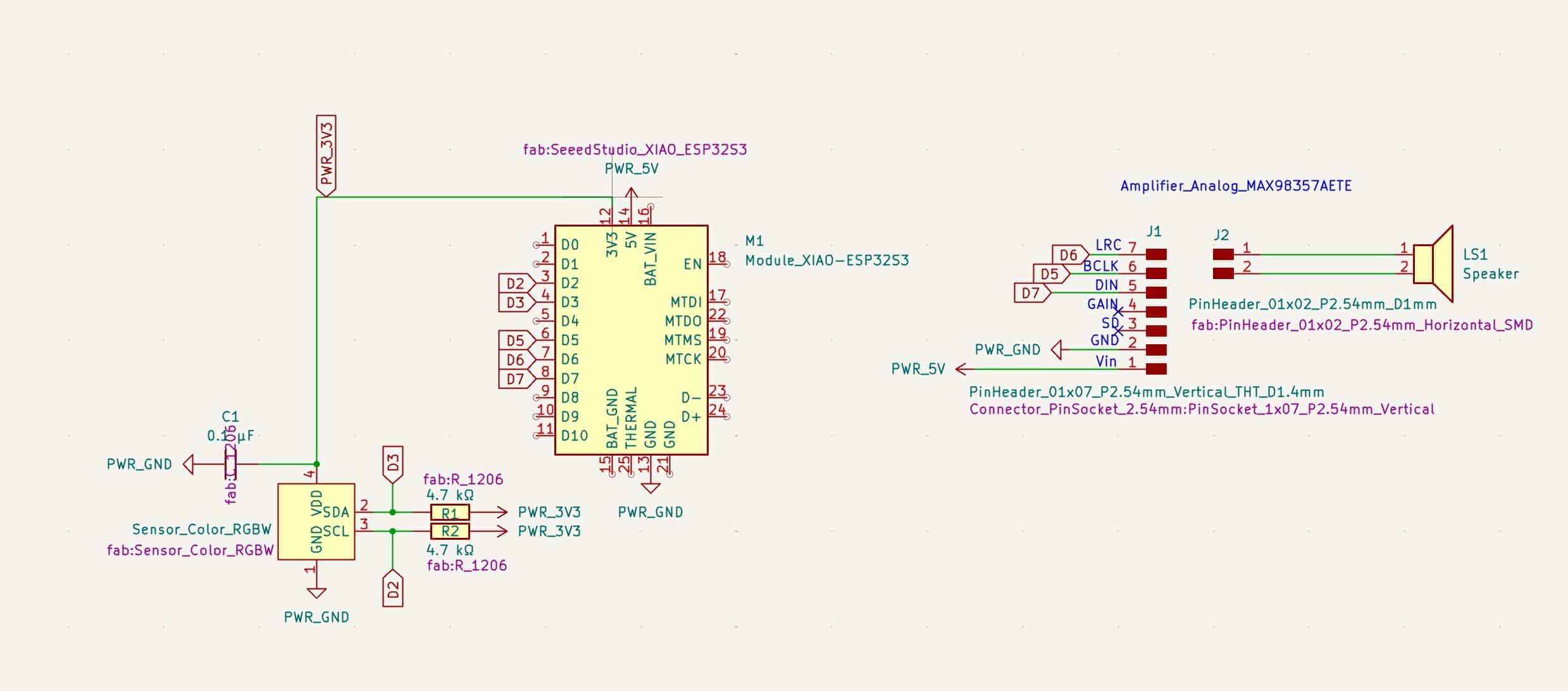
Designing the Board
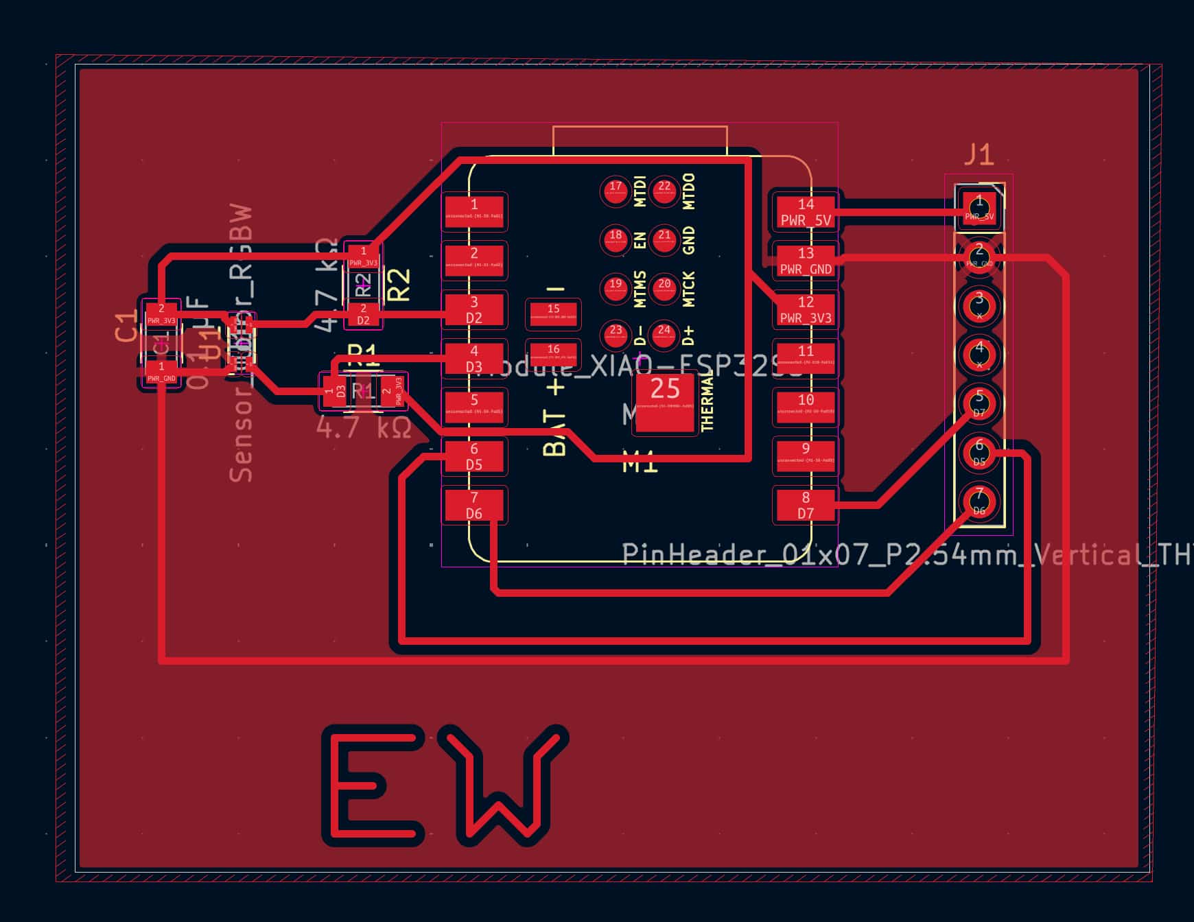
Here's my board design with everything laid out in KiCad:
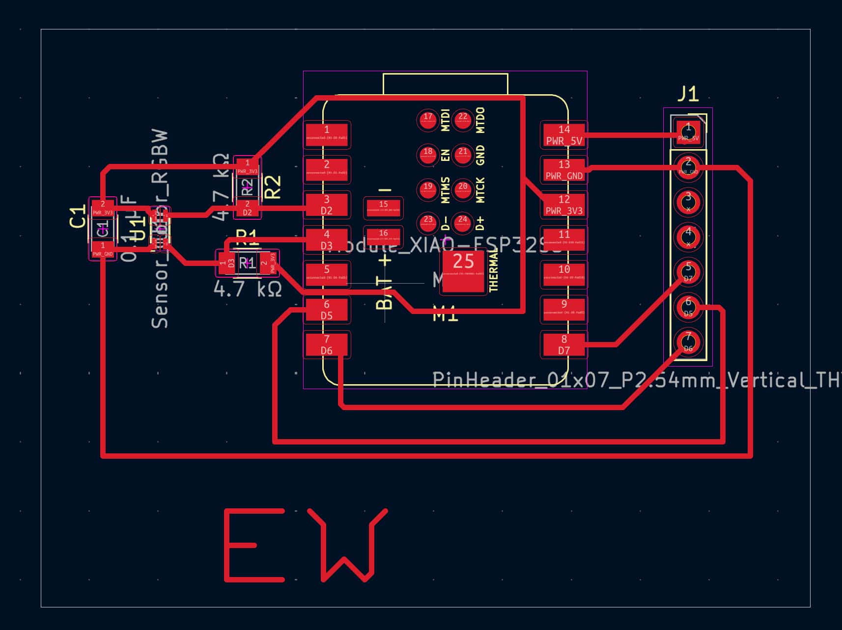
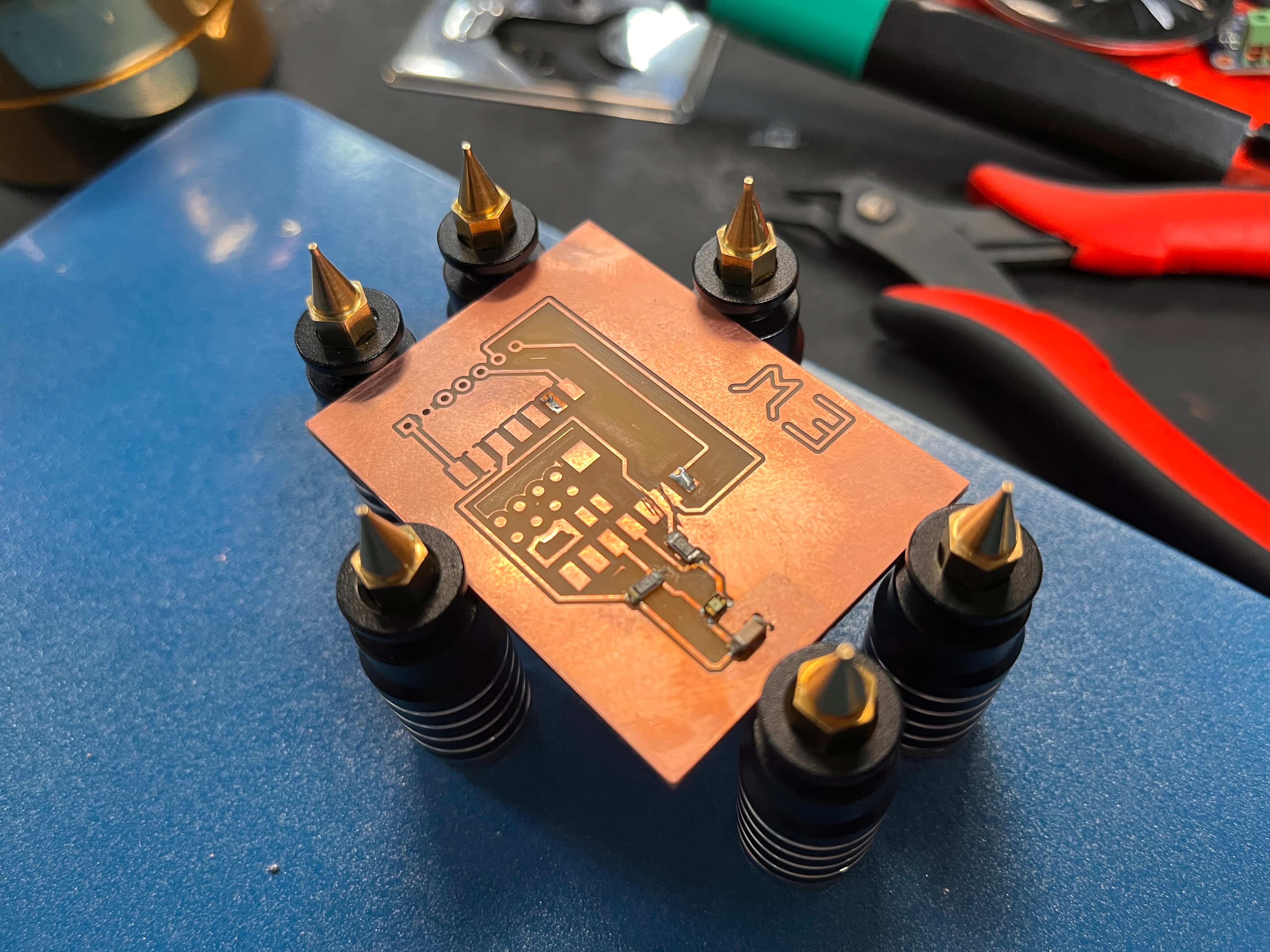
And here it is once I connected all of the components onto the actual board:
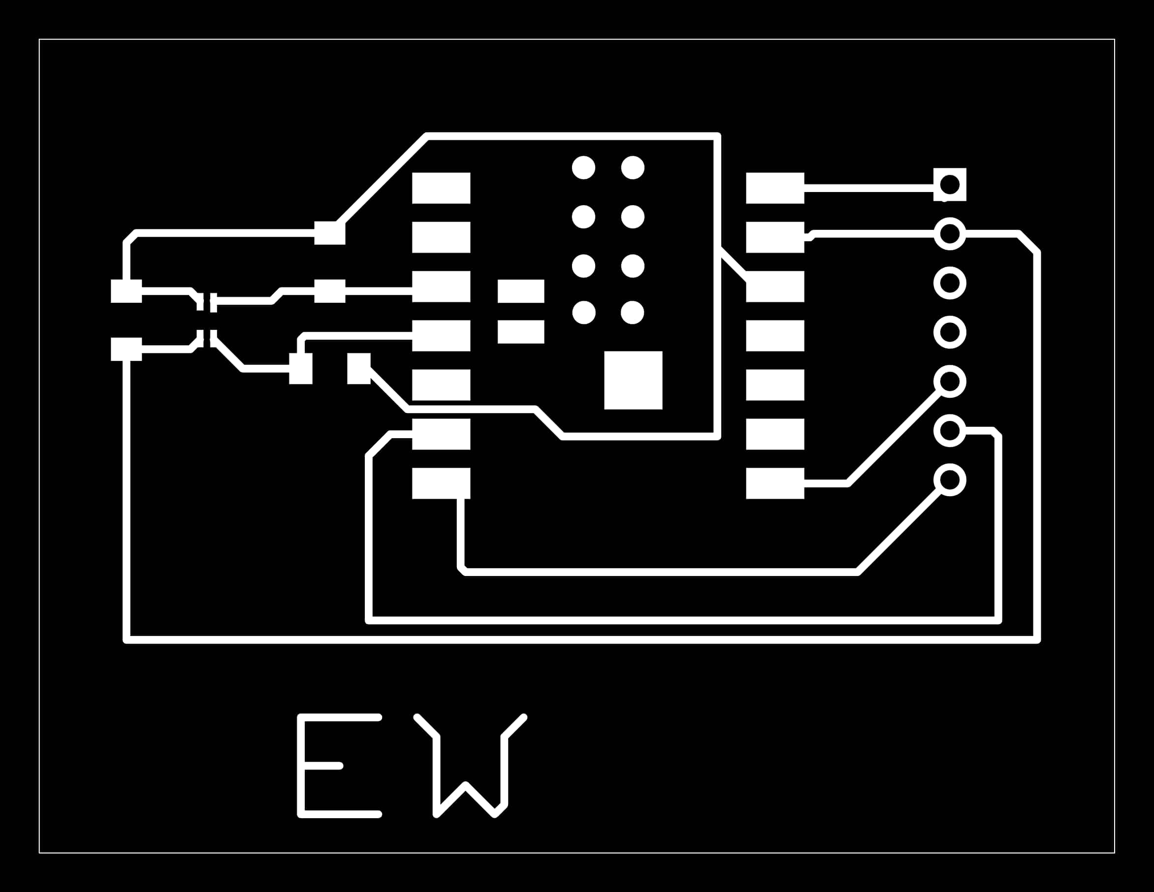
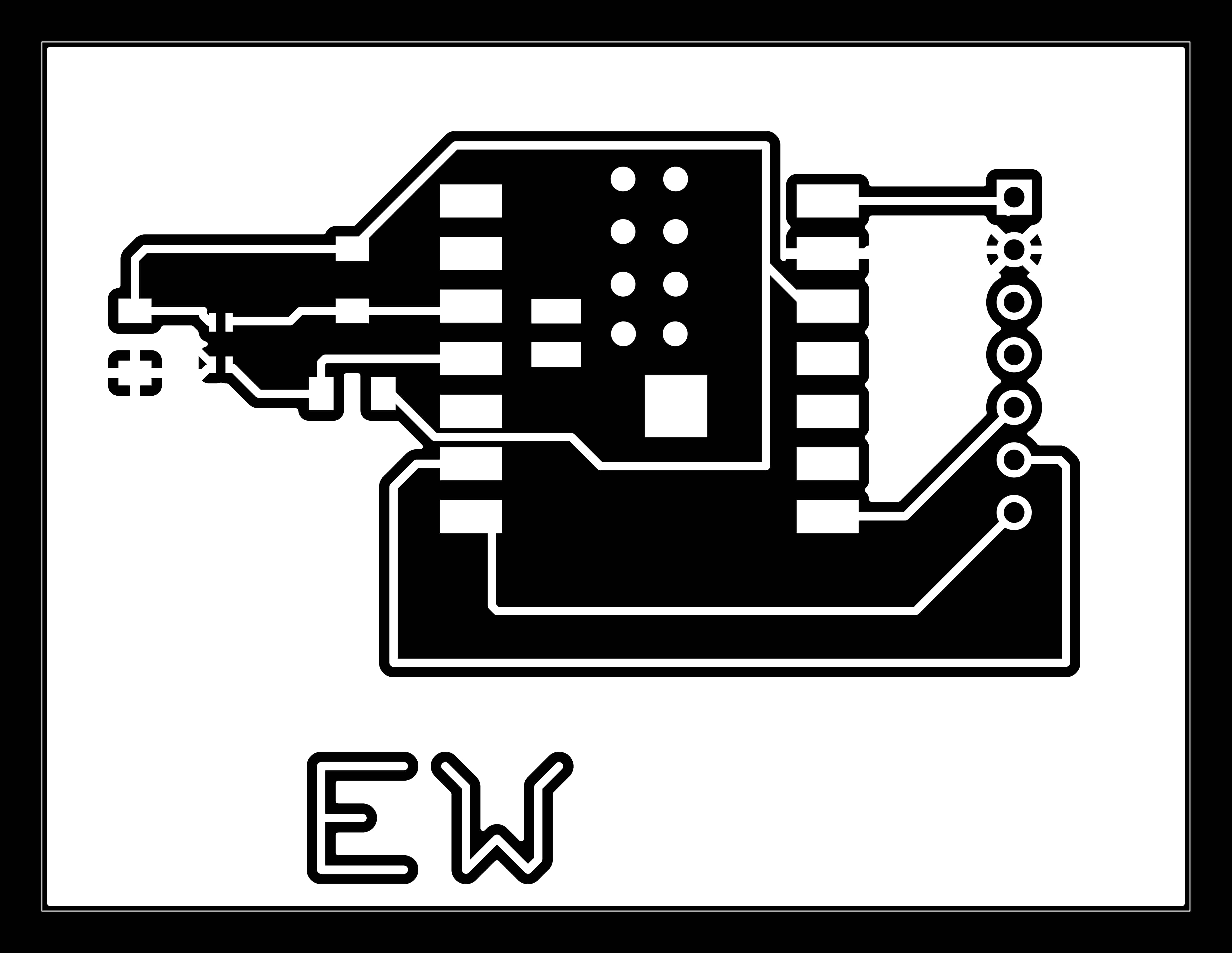
Just like last week, from KiCAD I generated my Gerber and Drill files, and dropped them into Quentin's "gerber2image tool." Here's the trace .png from that process:
Unfortunately, once I brought it into the "mods project" site / Carvera program, two pads from the RGB sensor that were supposed to be separated were conjoined. Let's go back to KiCAD and see if we can fix it.
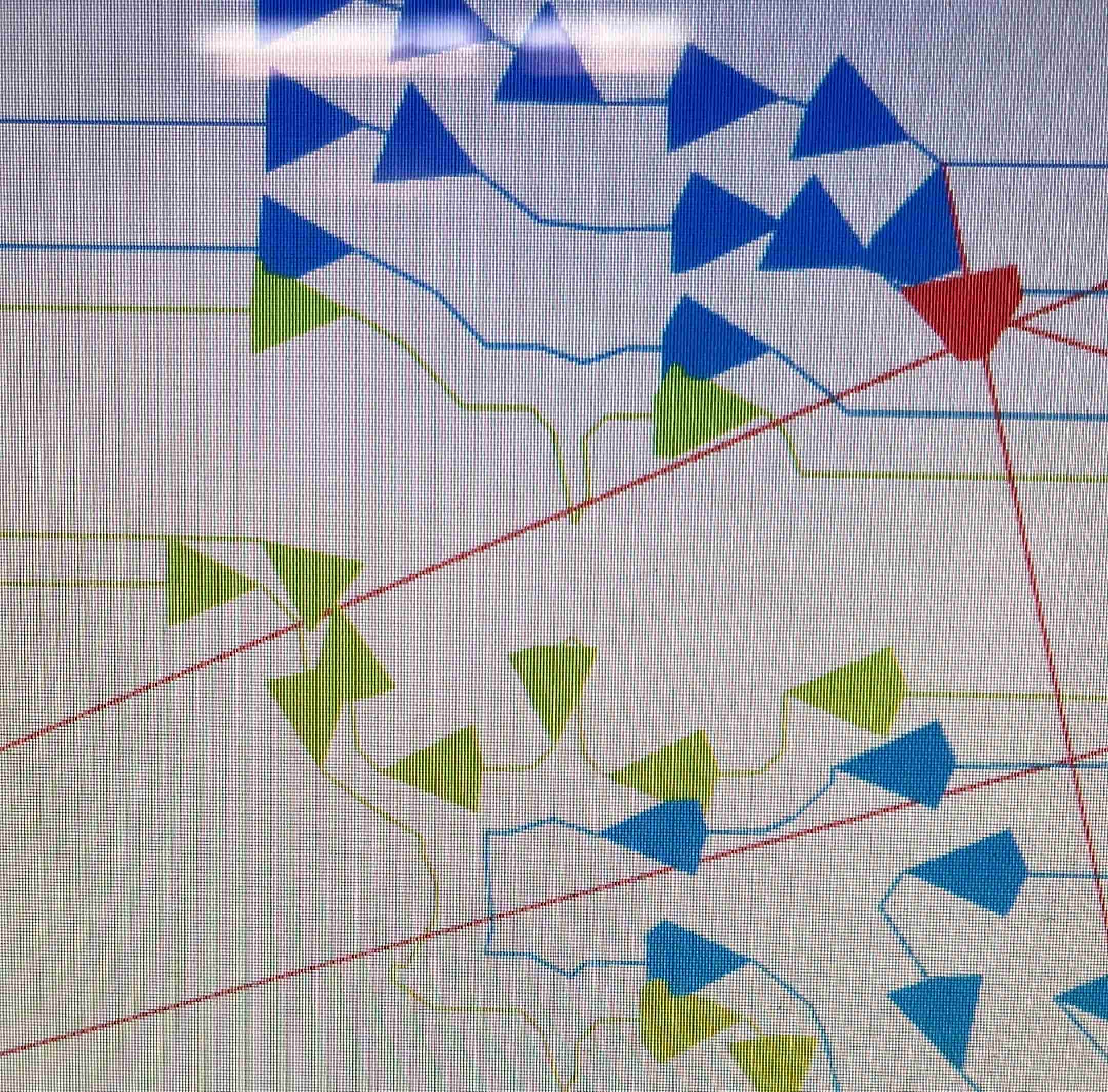
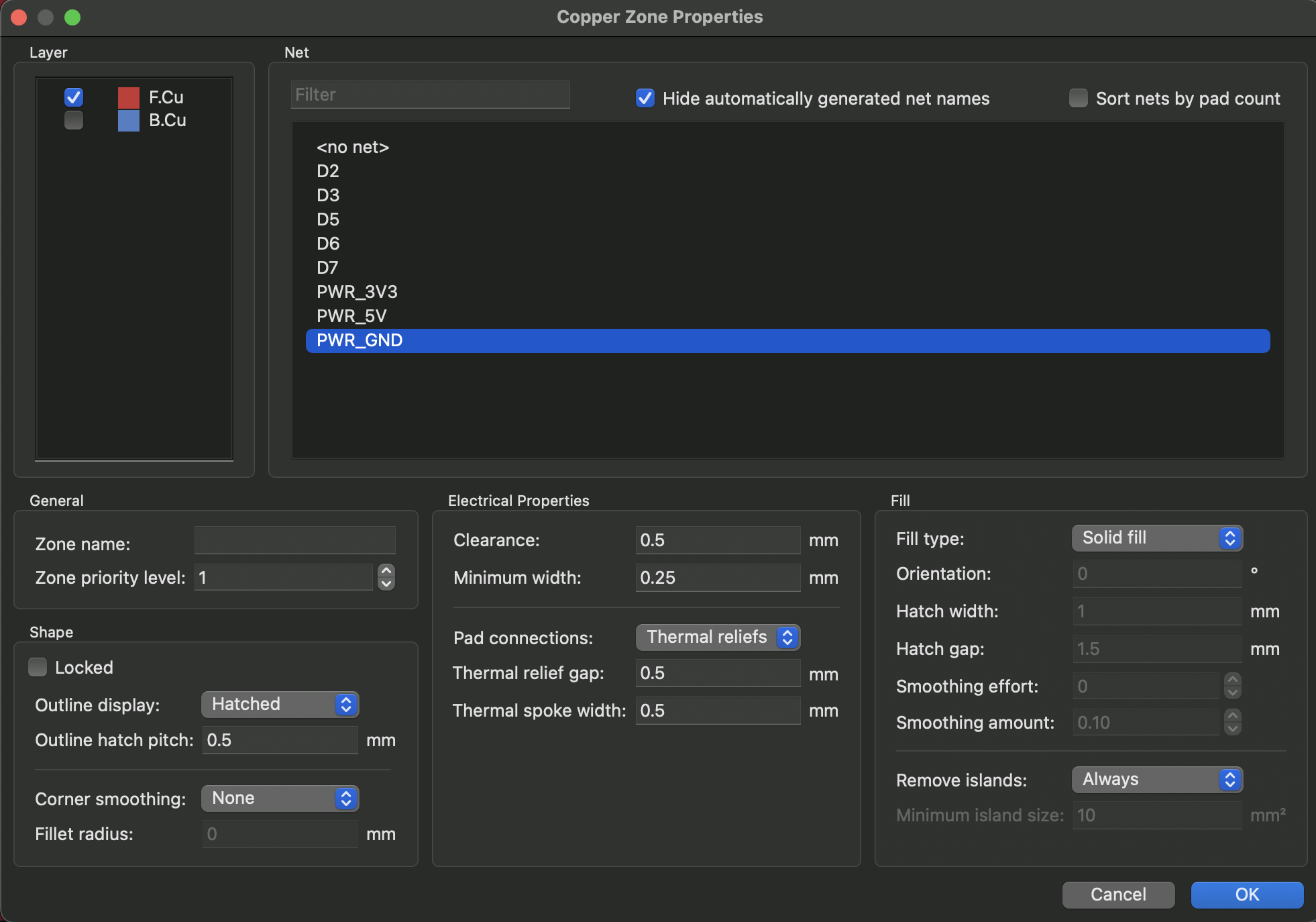
By double clicking the component you can edit the footprint, so we slightly moved them further apart and reduced the minimum distance for the tool to follow. Saetbyol also showed me that instead of wiring all the "GROUND" traces to each other, you can use the "Draw Filled Zones" tool on the front copper layer, then select "PWR_GND", then "Solid Fill" to automatically fill in the rest of your board with copper; this means all the "GND" traces are automatically connected through the rest of the board. This has a wonderful byproduct of also reducing milling time, since it no longer needs to mill out all the empty space where there aren't any traces.
Here's what that looks like:
And here's the updated .png from Quentin's Gerber2Img tool:
Once the board was milled, we're on to soldering! I hope it isn't the most difficult soldering job of my life.
The Most Difficult Soldering Job of My Life
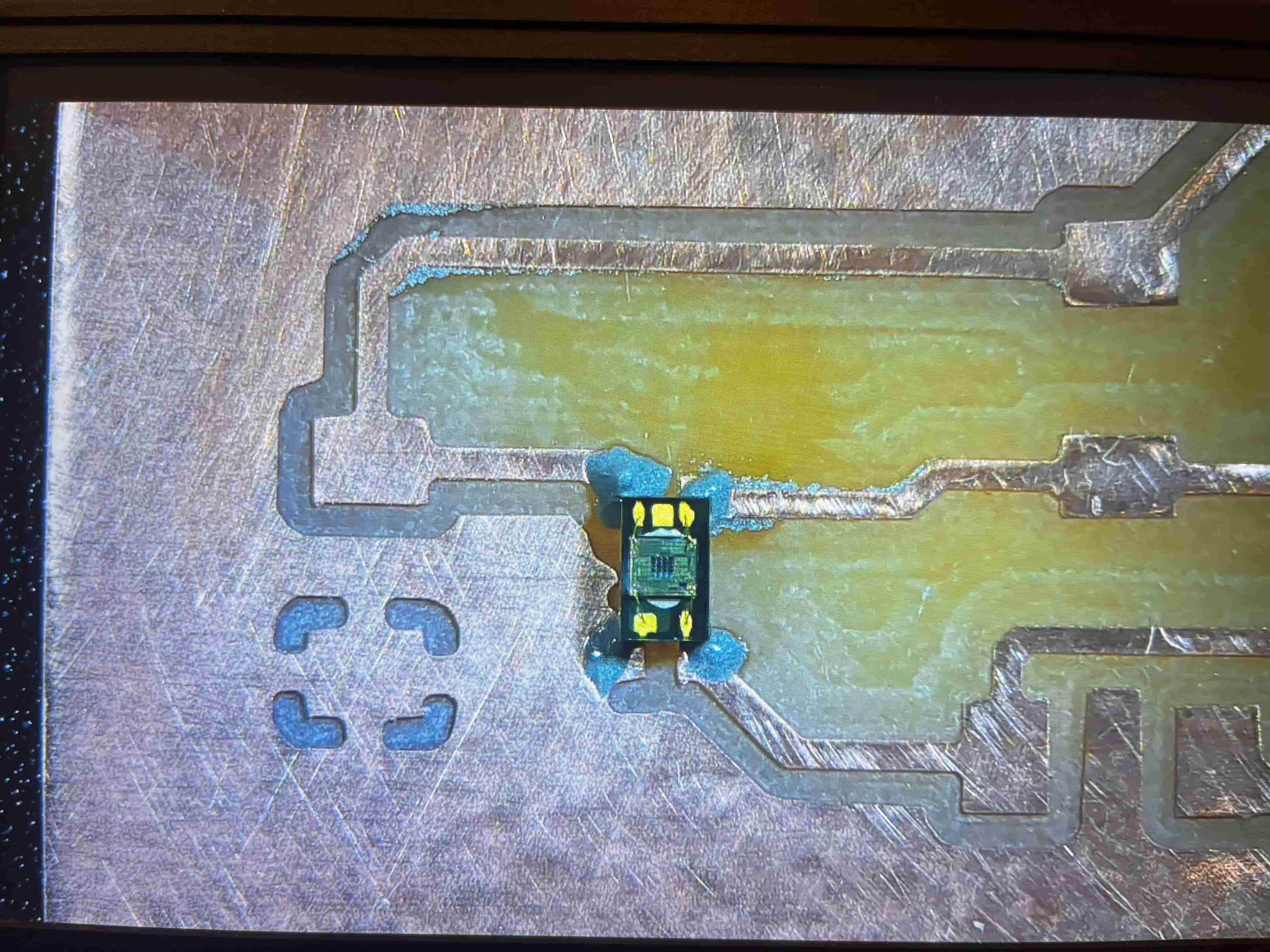
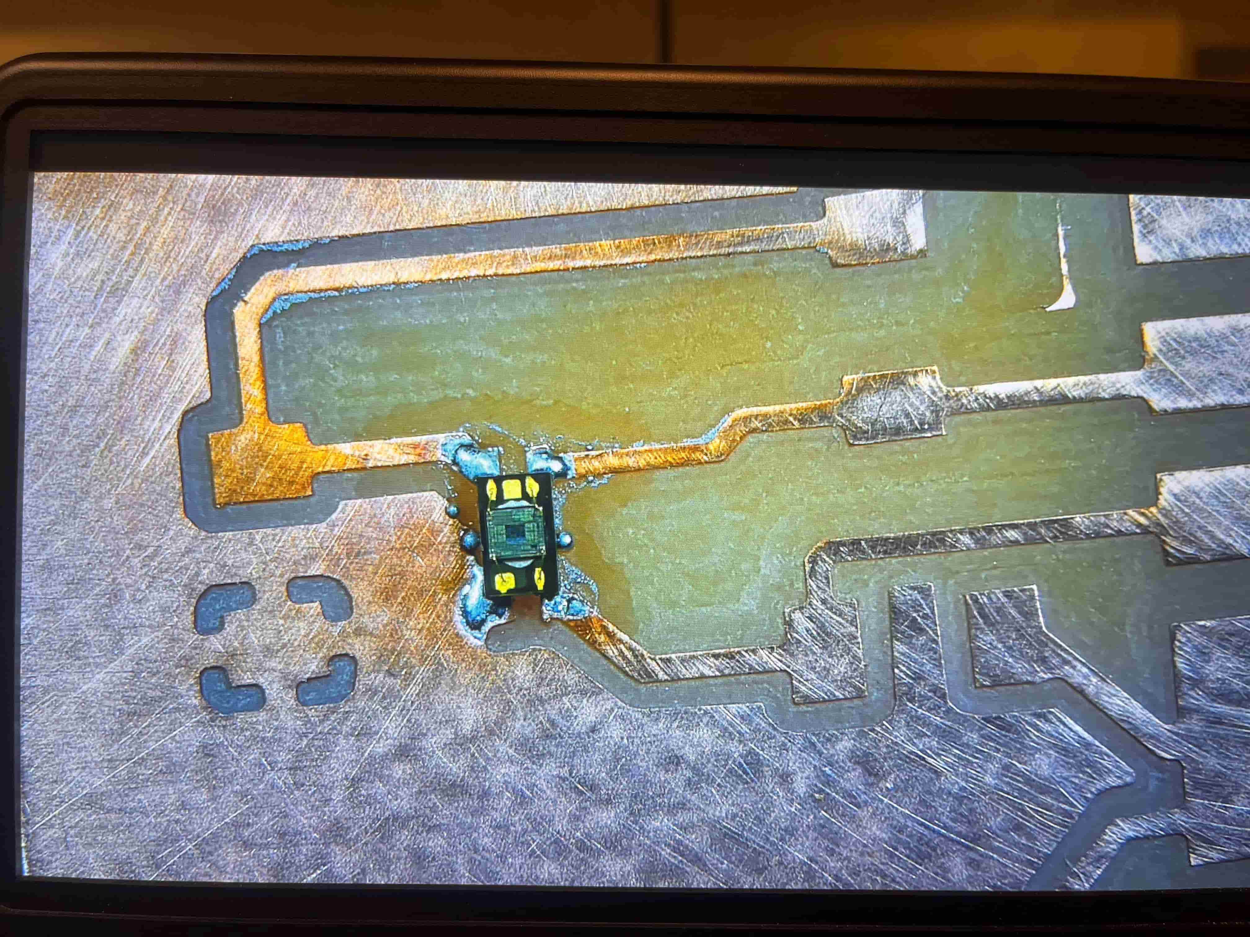
As it turns out, the RGB sensor is small. Like... REALLY small. Maybe 1/4 the size of a 1206 resistor. So after some inquiry, I was informed that the soldering paste was probably the way to go. I got the syringe, and gave it the ittiest bittiest press so just a TINY amount came out, and dabbed a little onto each pad; then I placed the RGB sensor on top.
Here's what it looks like pre-solder:
Then all you need to do is turn on the hot air gun, put your PCB under it until the paste turns shiny, and take it back out!
After that, I added in my capacitors and resistors, and began working on adding the microcontroller and speaker amplifier.
And here's the completed board:
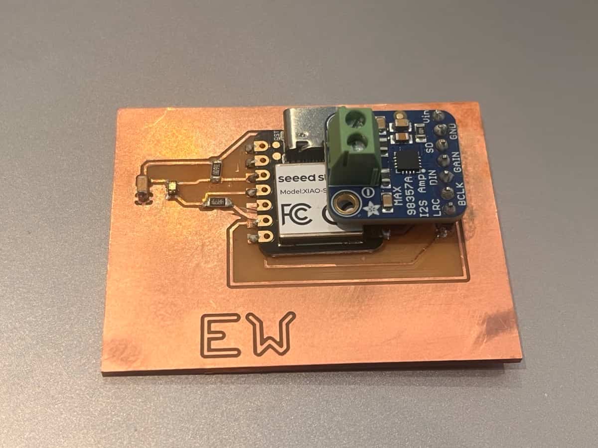
Unfortunately, upon testing the board with the multimeter, it seemed to indicate something had gone wrong with my soldering job – there were shorts detected simply everywhere, which was very disappointing, given that it'd all worked up until this point. I tested and tested and tested, and couldn't get it to work before class; butupon asking Neil, he kindly informed me I was doomed from the start, because I had been working with a double-sided board – meaning the moment I connected the amplifier with the through holes, I'd connected everything to everything on the back side.
That put a damper on this week, but I intend to revisit this device in the future – I really want to get sound working on this.
Ah, well. Lesson learned. Onward and upward to next week.