
IMPORTANT NOTE
Upon revisiting, this week really fits better under "Output Devices", while next week fits better under "Input Devices". Put another way, Weeks 8 and 9 should really be swapped. Instead of reorganizing all of the existing website file system, hopefully this note is enough to make it clear – please click here for my "Input Devices" assignment!
Overview
This week, we learned about input devices, which refers to any sensors or other component that can read information from the physical world. The assignment was:
- measure something: add a sensor to a microcontroller board that you have designed and read it
Project Files & Links
- Week 8 Lecture Notes
- Week 8 Recitation Notes
- KiCad Files
- ESP32C3 3D Model
- Arduino Files
- HTML Interface
- ESP32C3 Housing 3MF Print File
- ChatGPT PDF 1
- ChatGPT PDF 2
Group Assignment
Our group assignment was:
- probe an input device's analog levels and digital signals
You can find what our group did to complete it here.
Brainstorm & Design
This week, our class learned about the different types of input devices that might be used when designing our projects. From microphones to temperature sensors to cameras, each type of input can be added to our PCB boards to do different things. So the first step was to think of what to do this week.
In my case, I wanted to start working towards my final project, which will need to take in texts from me and print them out on a receipt, while also lighting up, controlling a little popout bird, and emitting sound. I knew I could focus on those output devices in future weeks, so in this case I wanted to test what input would be necessary: the WiFi system that could take in my message. I figured the easiest way to do this would be to find a chip with an embedded WiFI system, attach an antenna, and display the output on a tiny screen.
After doing some research, and checking our inventory, it seemed like the XIAO ESP32C3 could do exactly what I was looking for. To confirm, I checked with ChatGPT while linking each of my components; from there, it helped me figure out which pins needed to connect to which components, and acted as a great double-checker of my work when I needed it. The full chat can be found in the "Project Files" section above, or here.
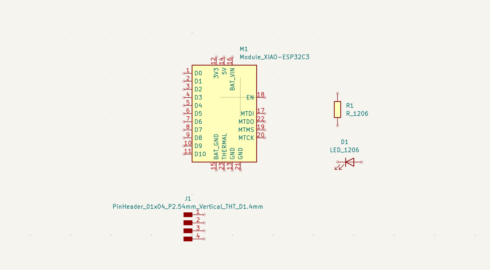
Here are the components I used, when I first laid them out in KiCAD:
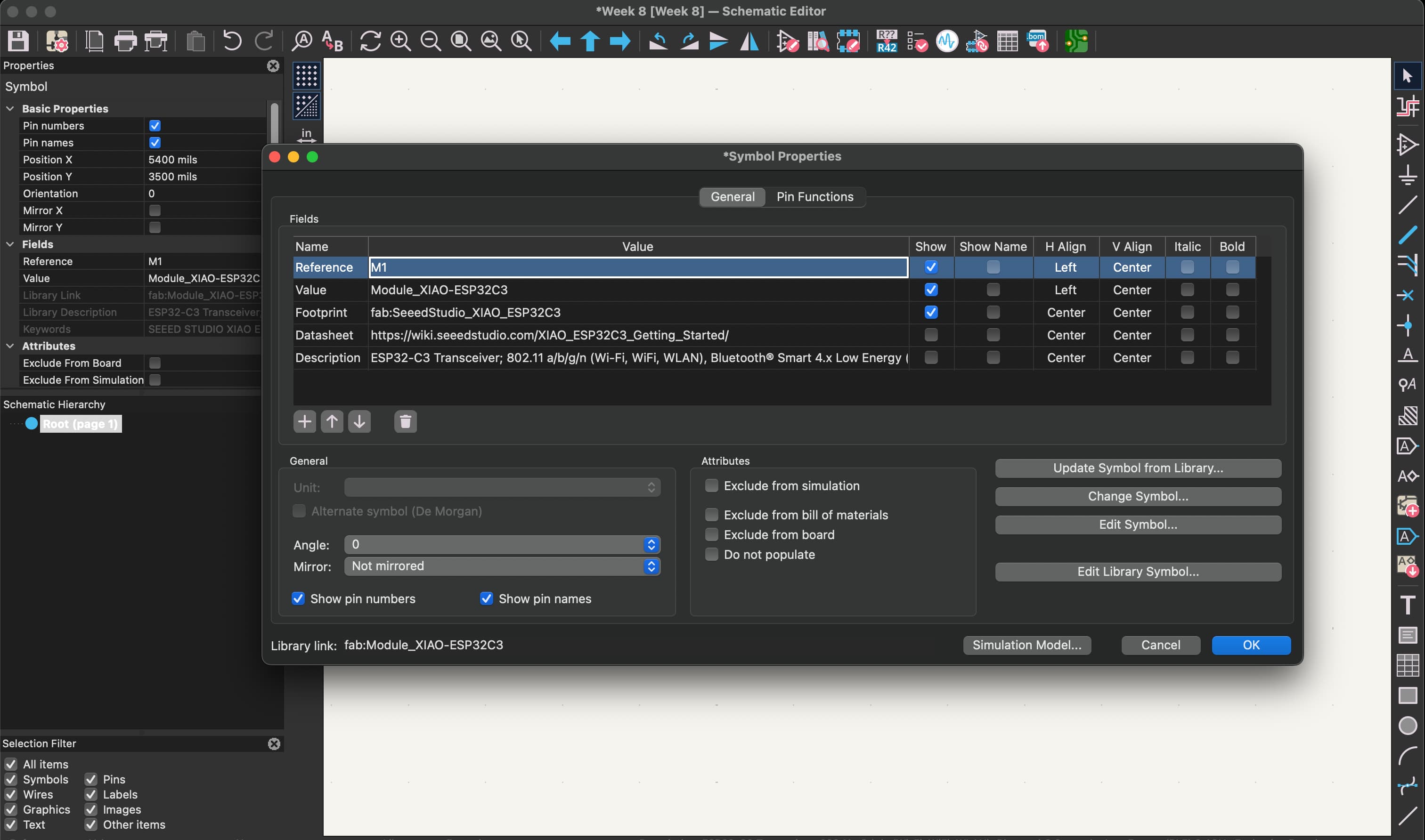
And here they are once everything is connected, using the tag system to conect wires through names tags:
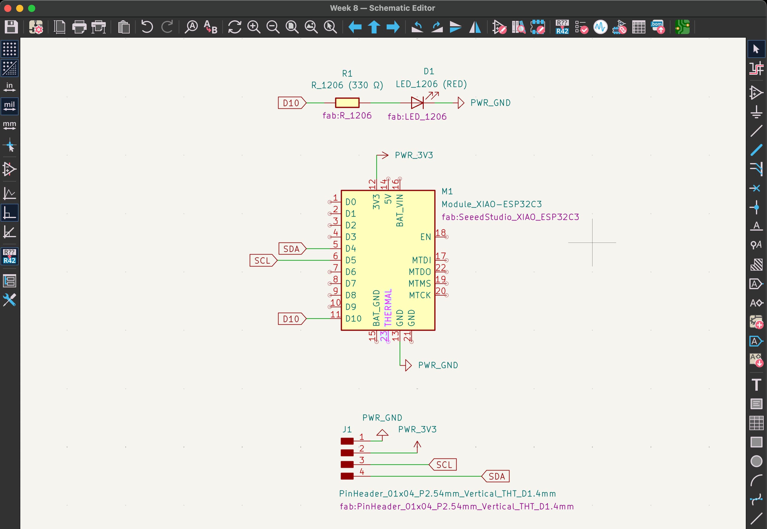
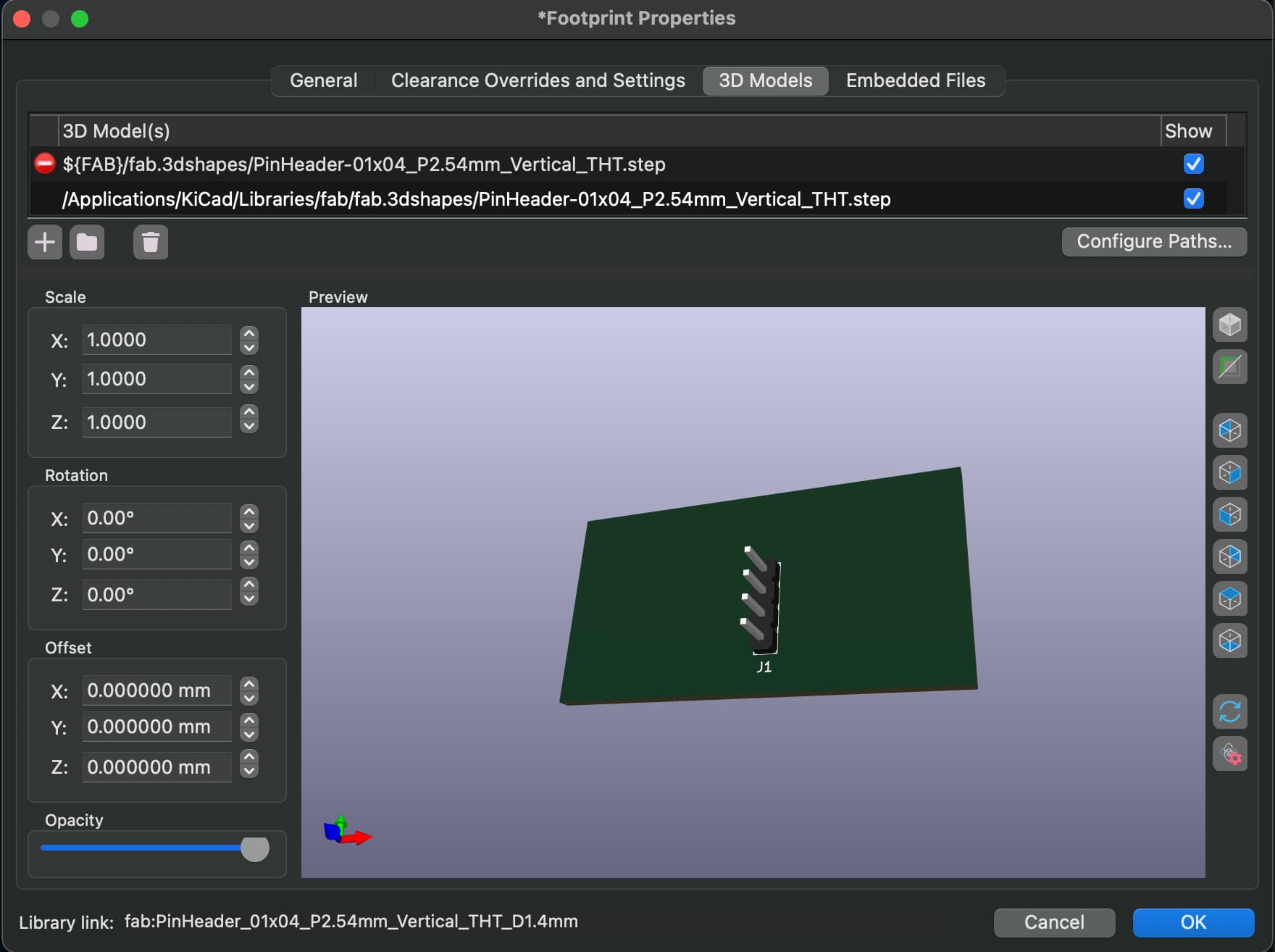
Make sure you double click each component and enable the footprint!
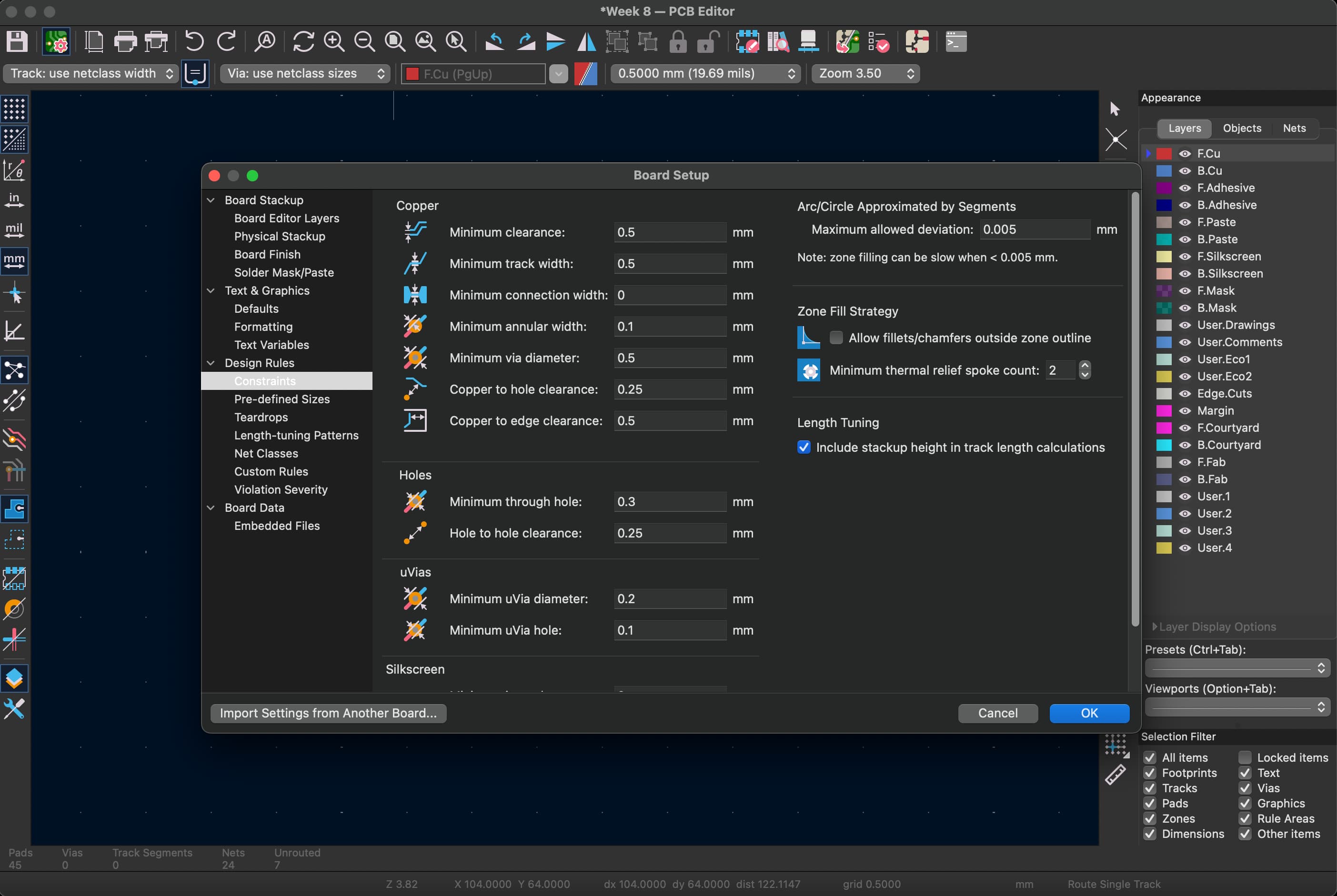
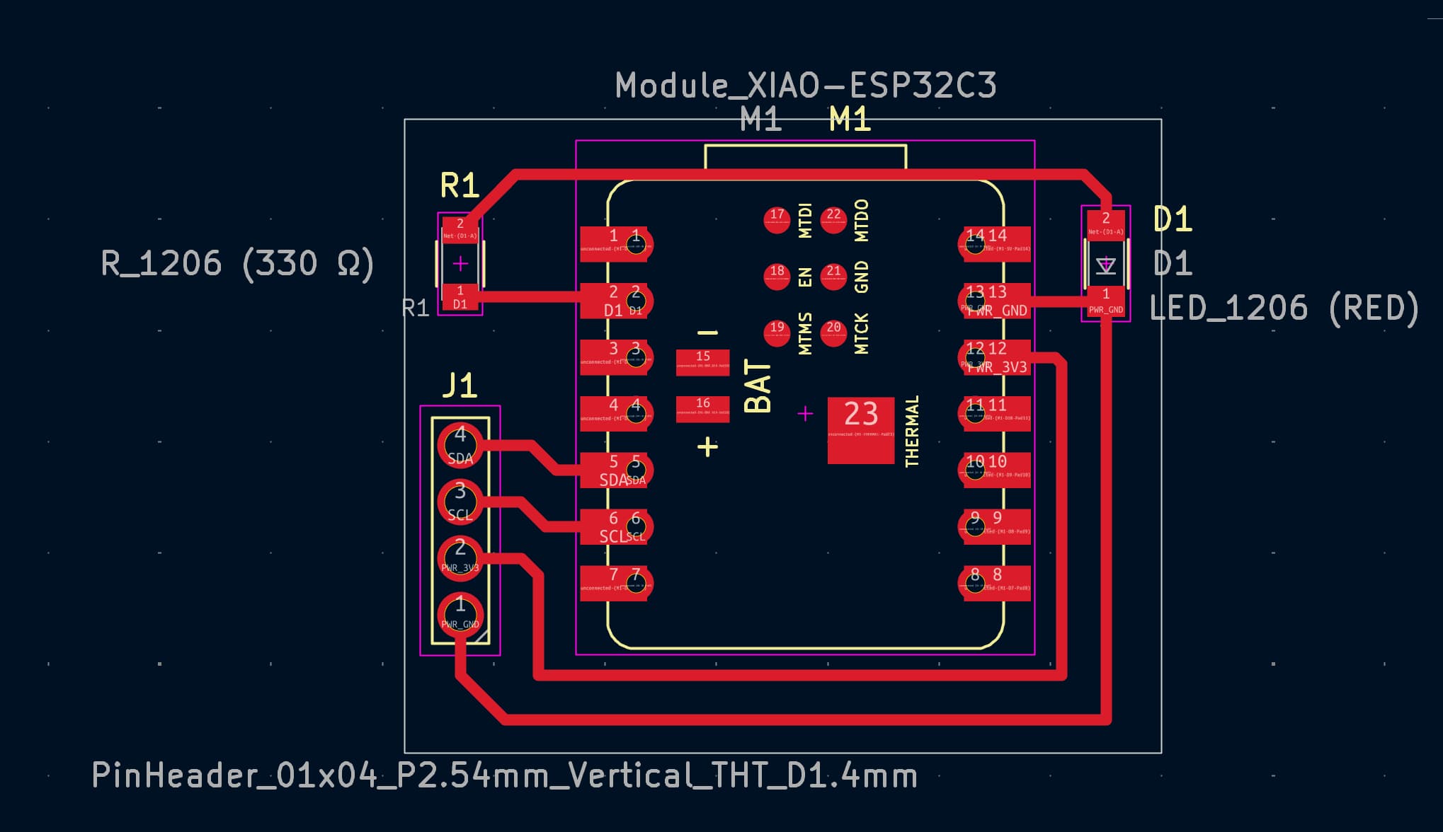
I then exported into the KiCAD PCB view, where I started actually designing how each component would be connected on my intended PCB board. I made sure to up the minimum clearance to 0.5mm based on what we found in previous weeks.
Here's my board once I connected each of the components and added the square board shape as the platform to mill out:
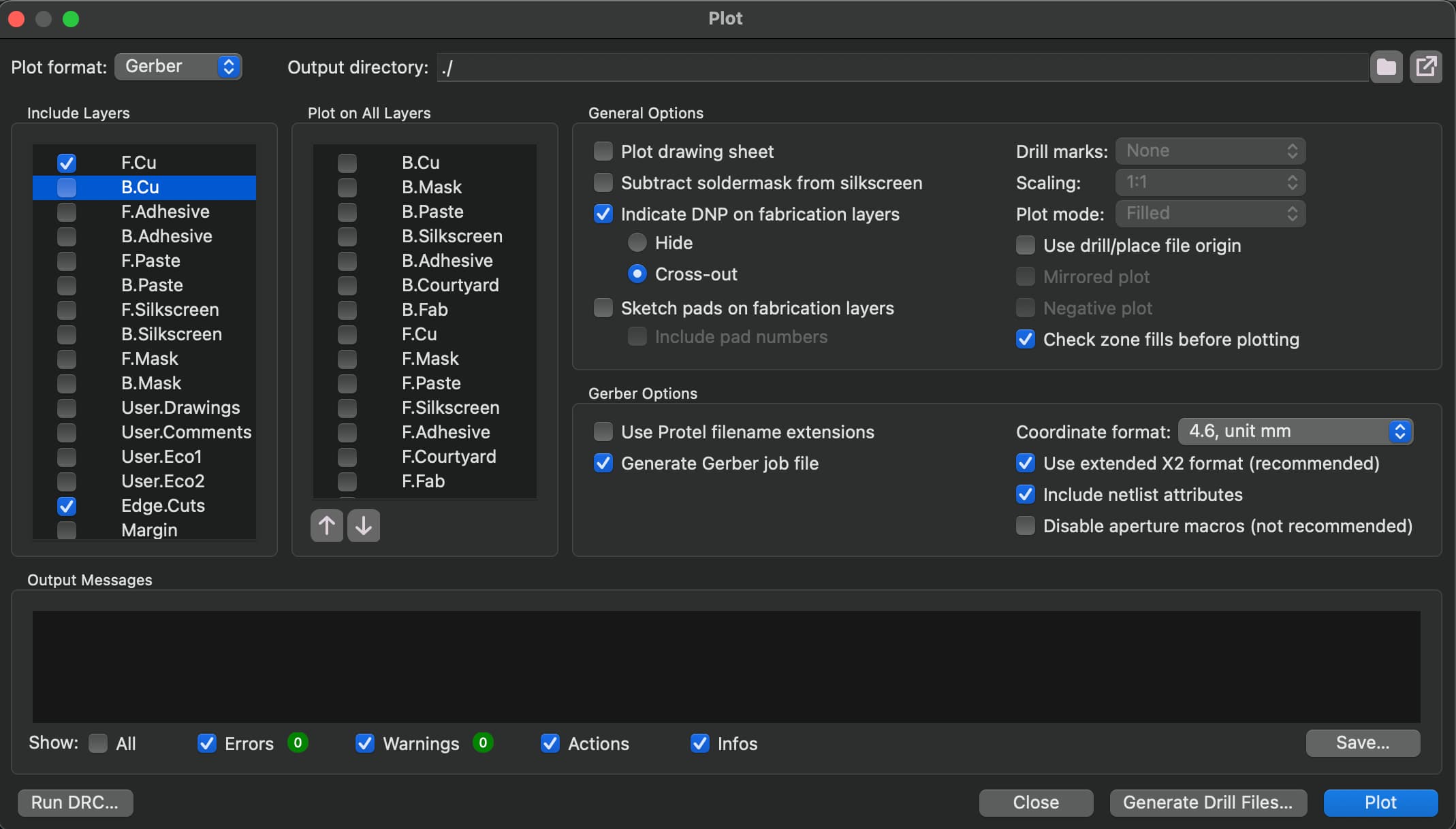
Lastly, I exported my Gerber files as well and generated the Drill files which I will use in the next step to mill my board. Make sure you generate the Drill files, because I milled two test boards before I realized why the holes weren't included!
Milling My Board
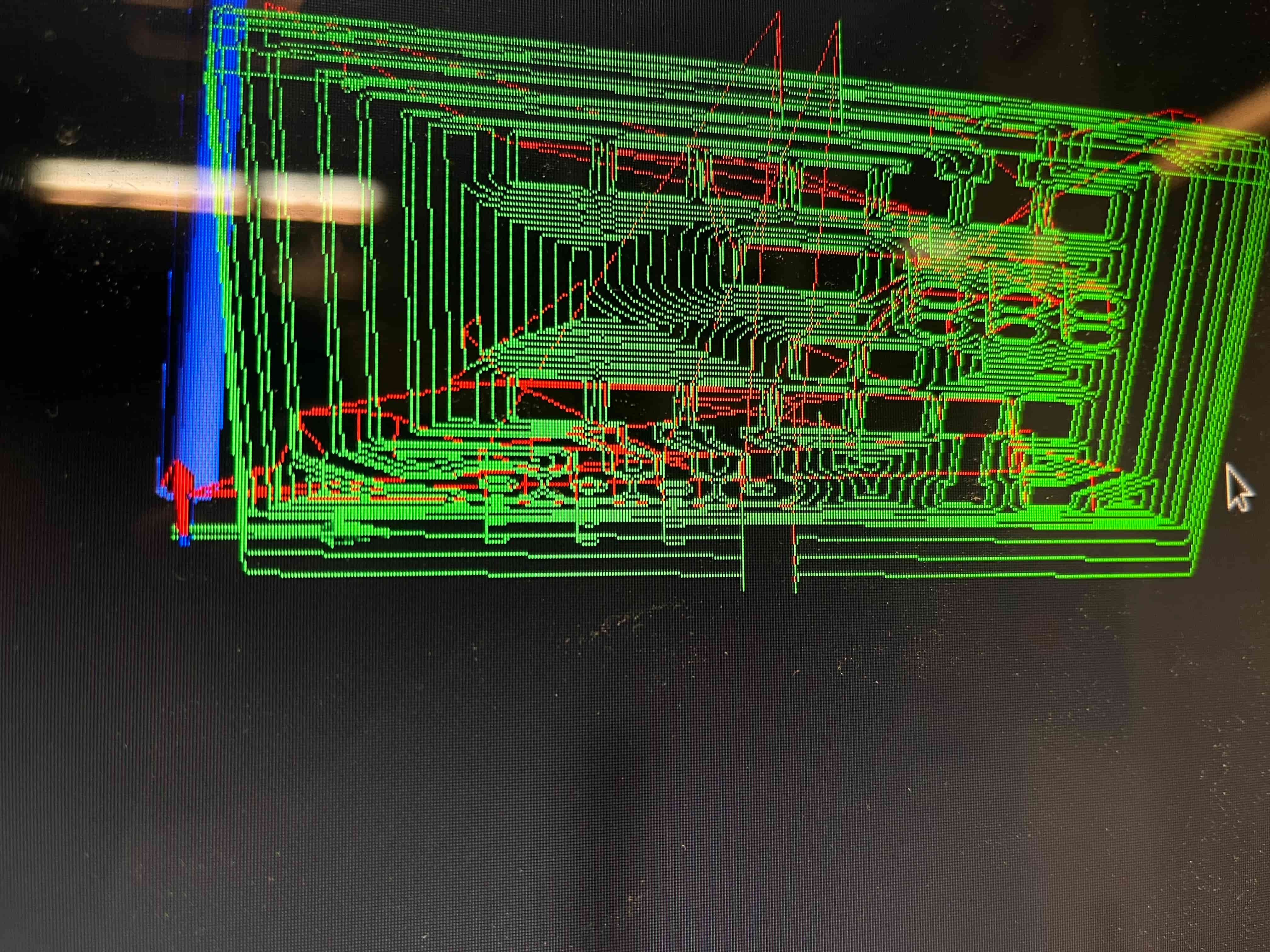
Now that I had my Gerber and Drill files, all I needed to do was drop them into Quentin's "gerber2image tool." That generates the two .pngs pictured below:
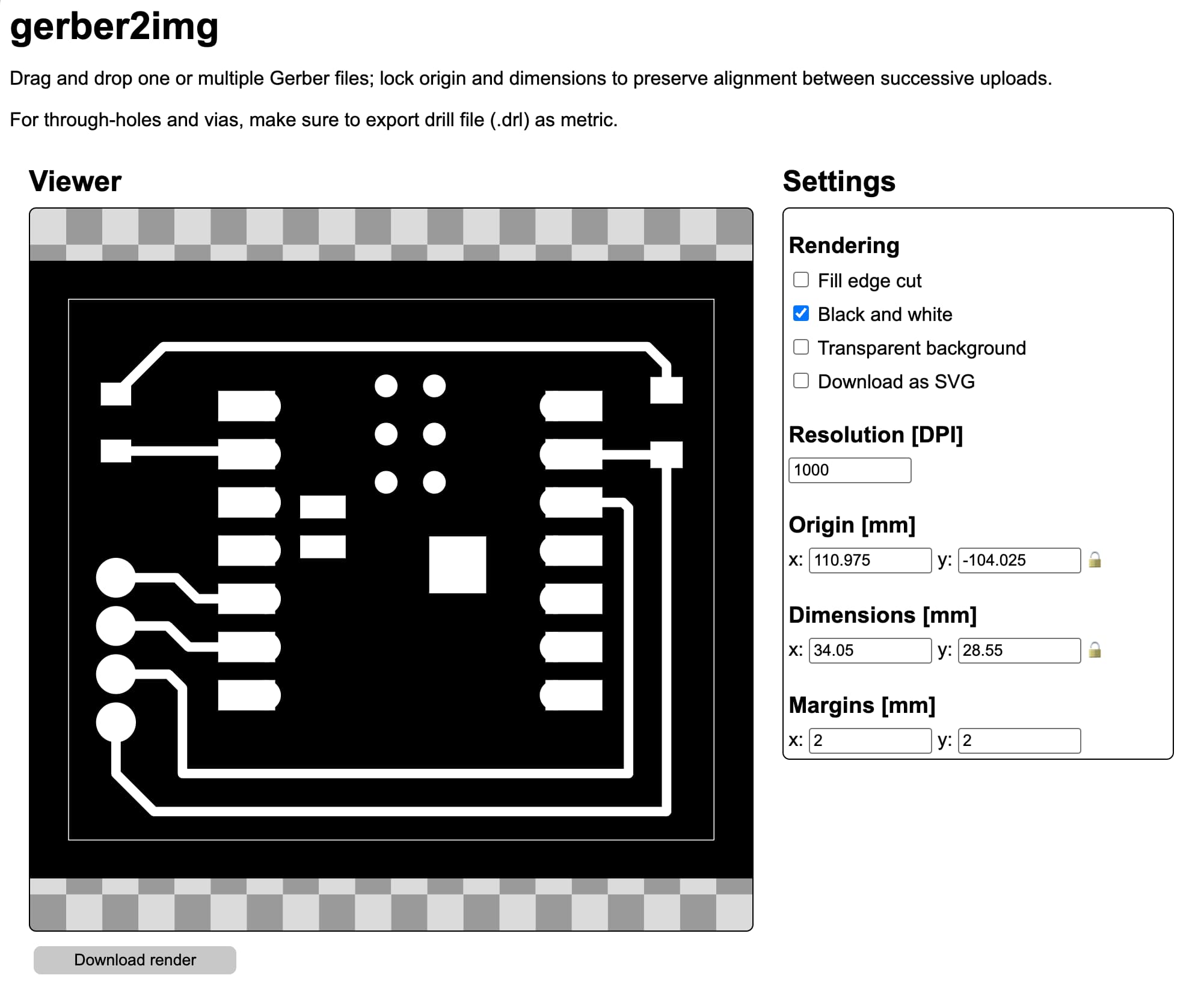
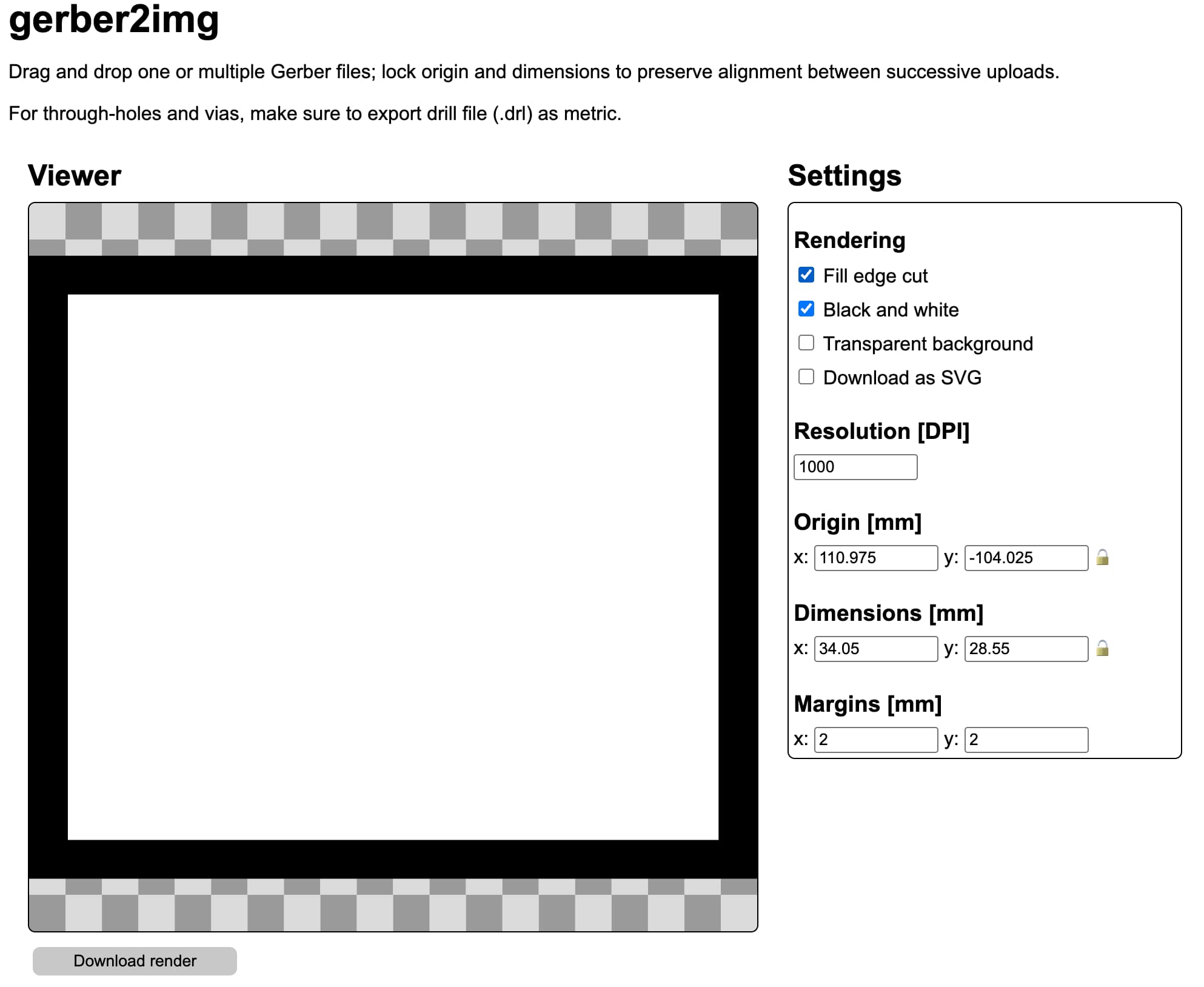
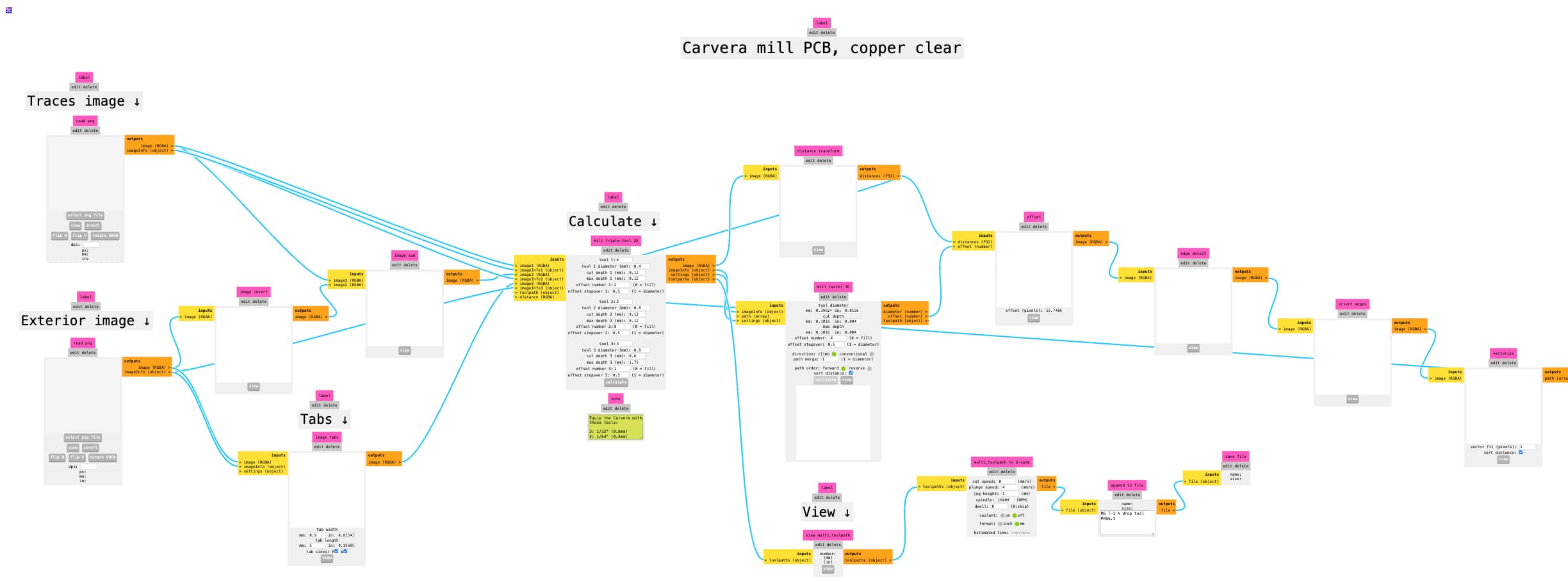
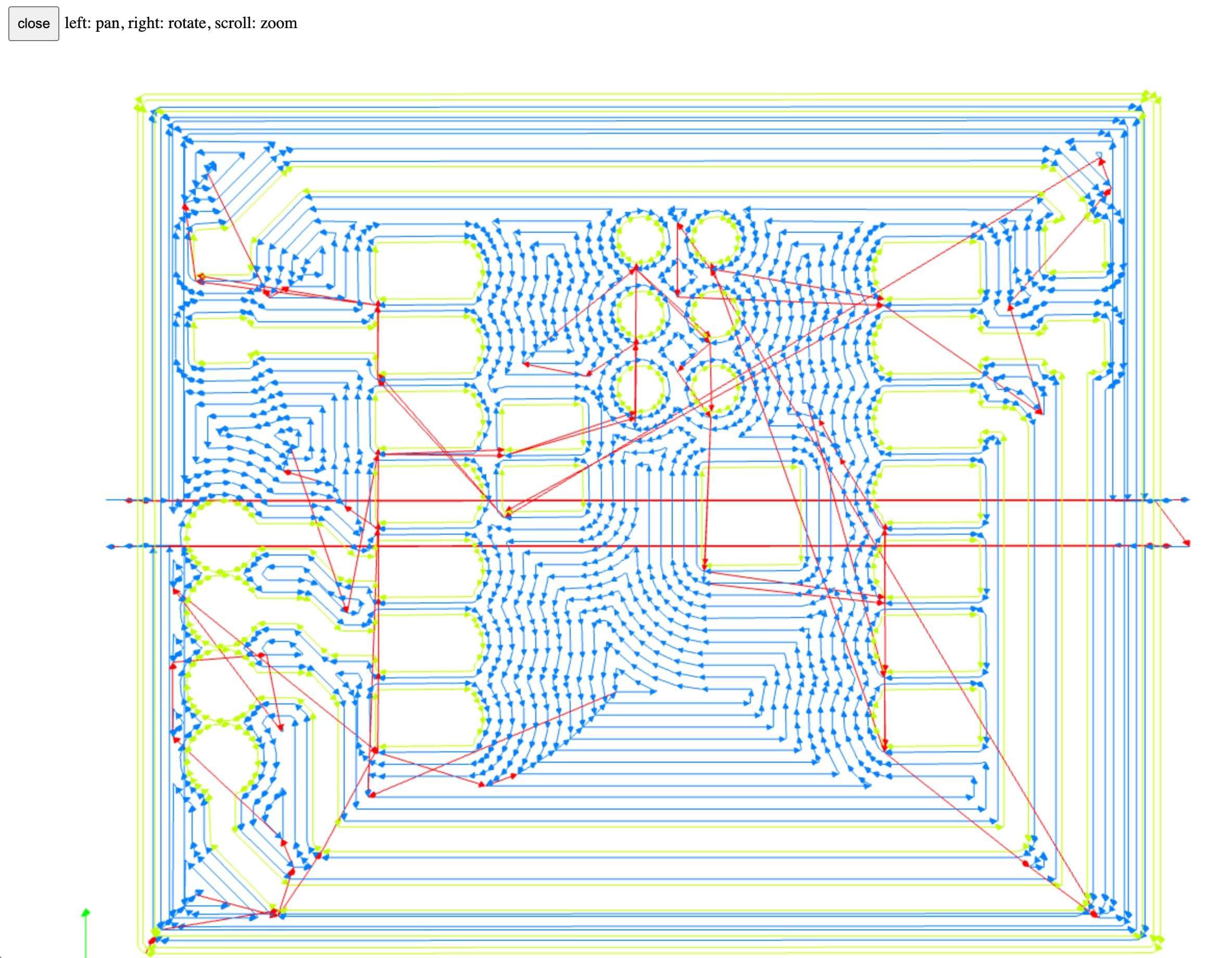
From there, I opened up the "mods project" site, then right clicked into programs –> open program –> "Carvera mill 2D PCB all". Then I dragged the trace png into "Traces image", and the board png into "Exterior image", and hit "Calculate". This generates the correct file for the milling machine, as well as a 3D model with the milling path within your browser (also pictured below):

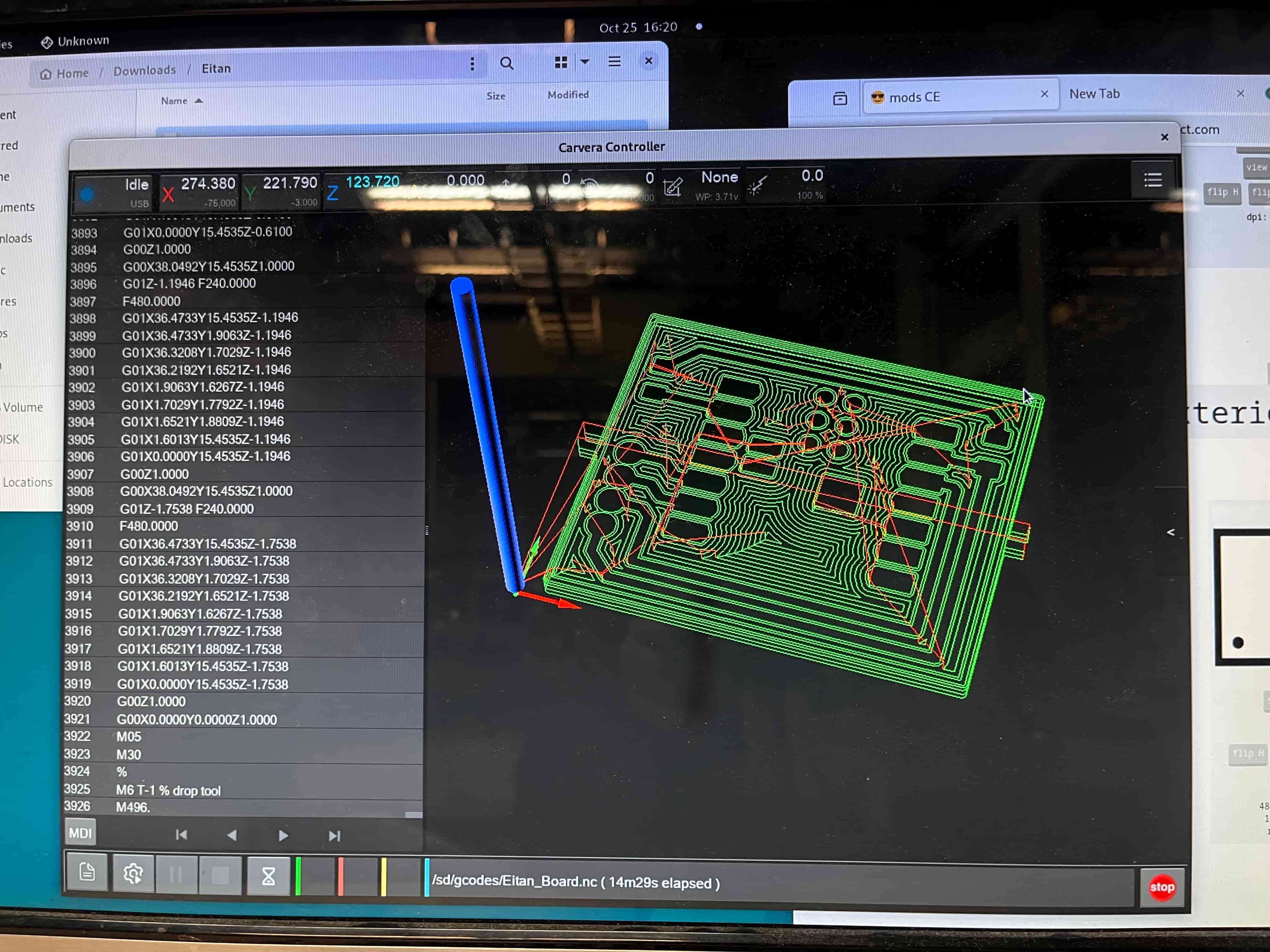
Then I brought my .nc file over USB to the milling machine, plugged it in, made sure the offset was aligned with my intended board shape (avoiding the screws holding the board in), and hit "Run"!
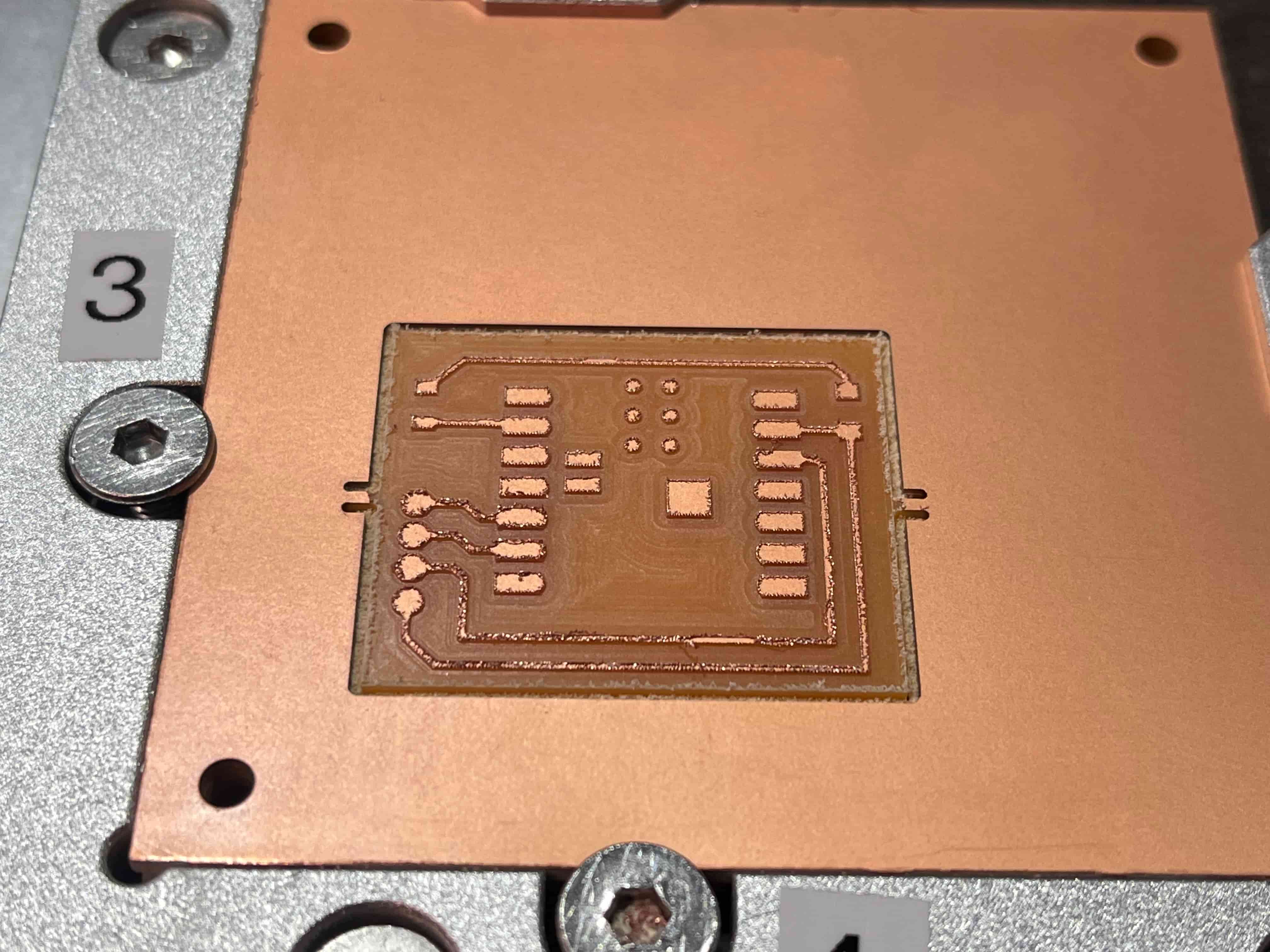
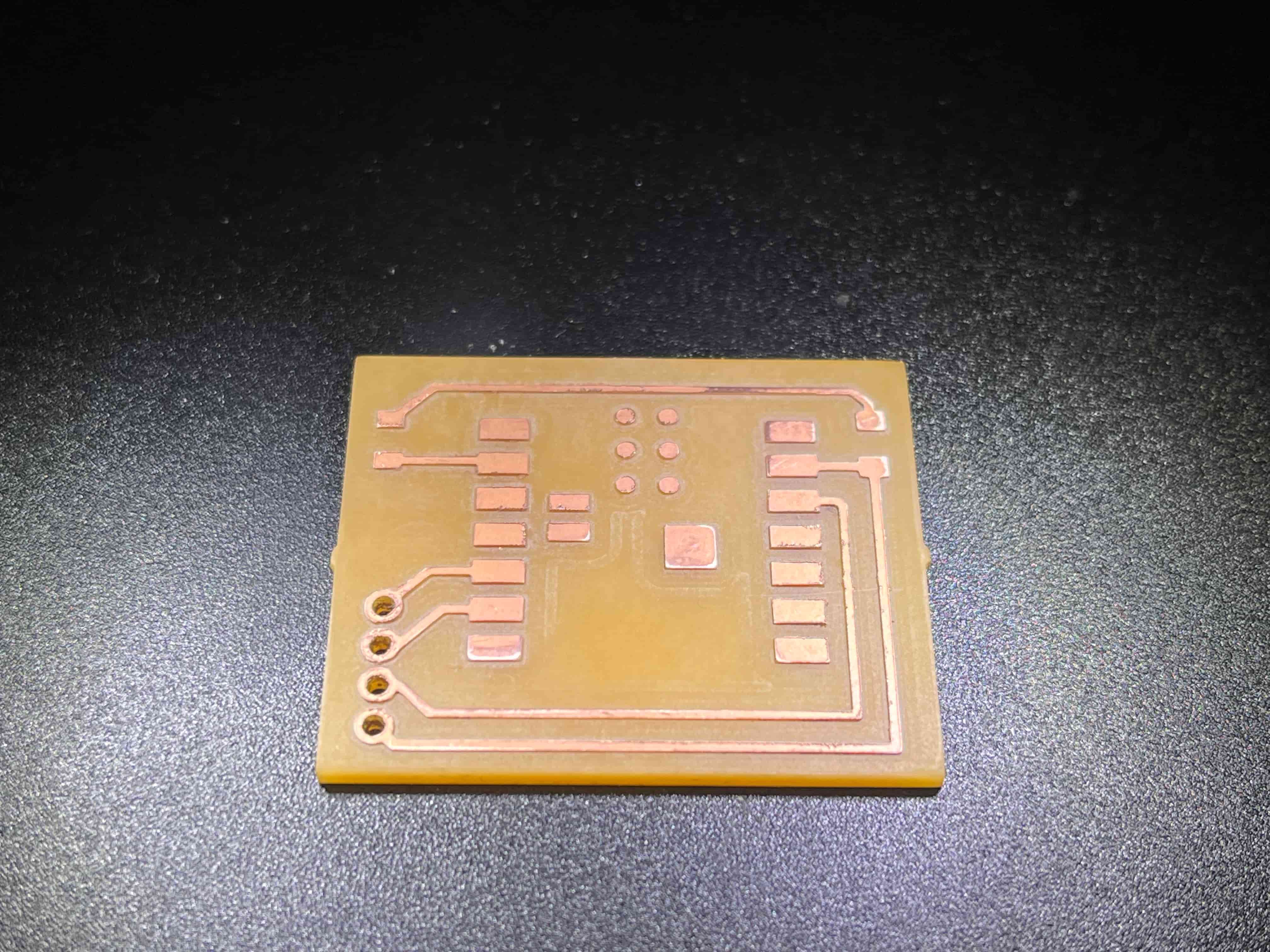
How beautiful!
From there, I followed the steps from previous weeks – clipping out the board from the tab attachments, sanding it down (wet sanding really does help, in both clearing out material and making sure everything stays smooth!), and basically just making it look beautiful.
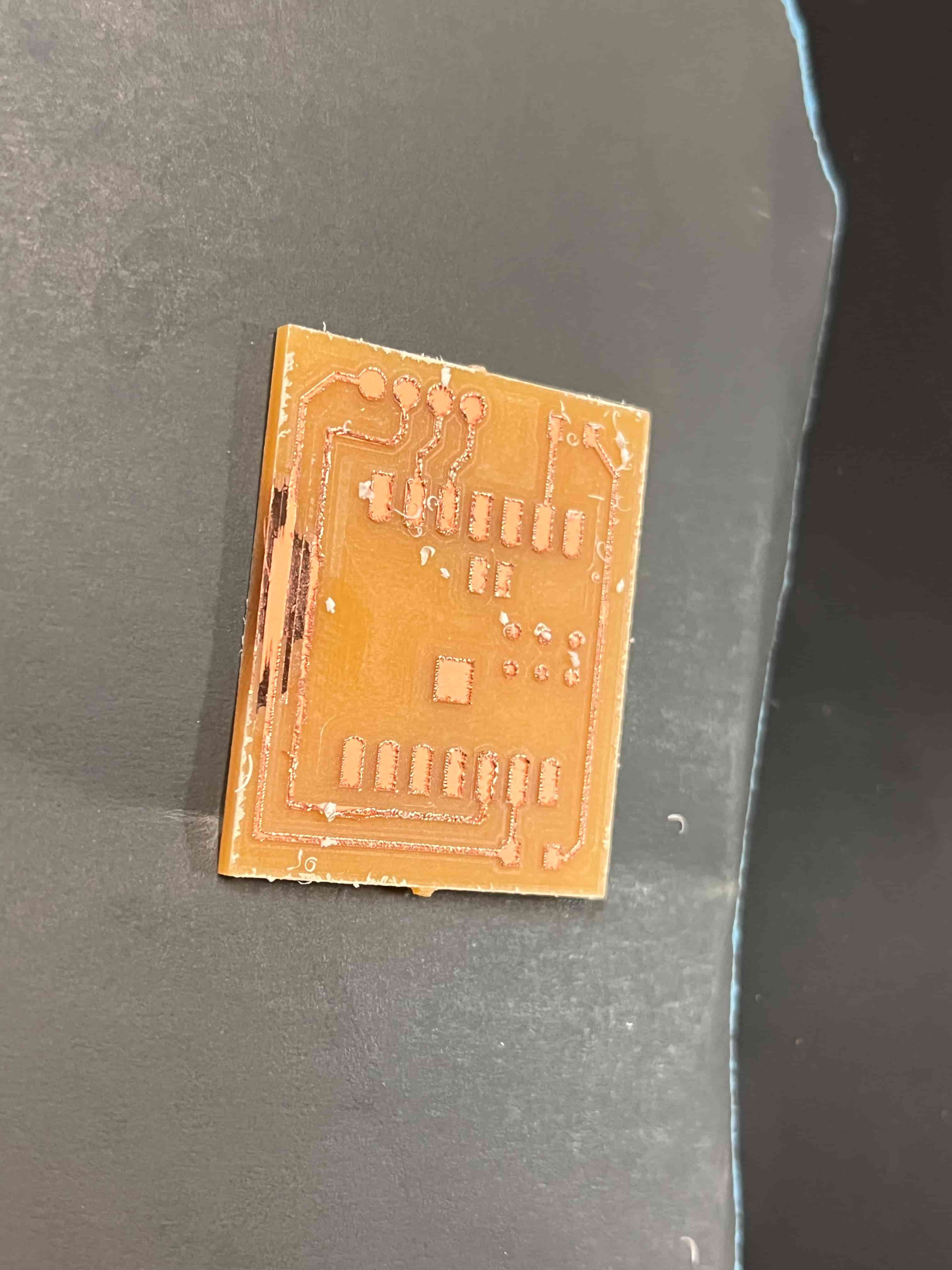
...but you know what's missing? Holes. Holes I needed for pins, to solder the OLED screen onto the board. Oops.
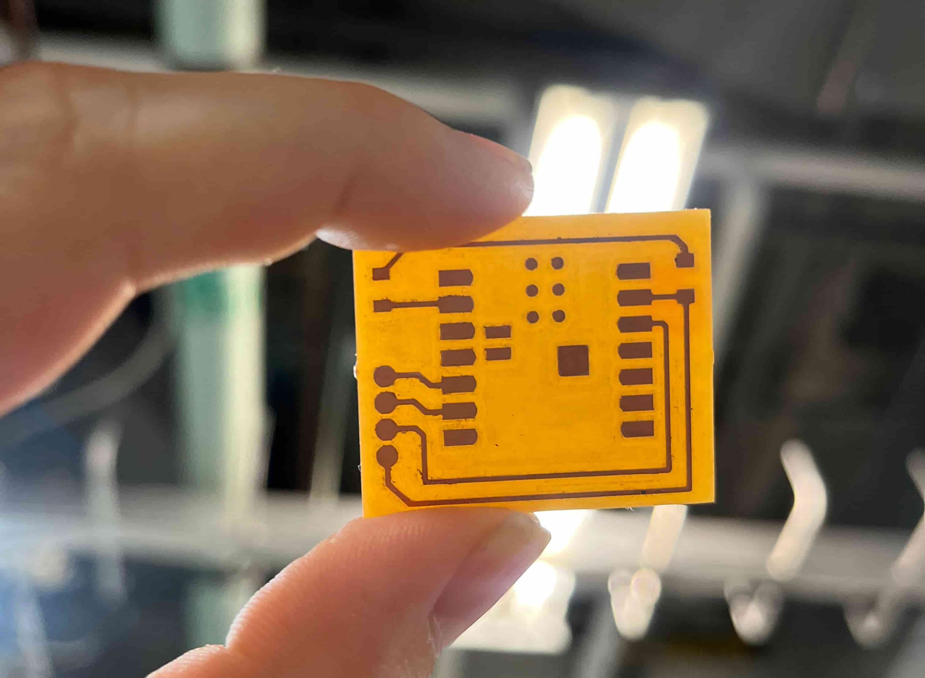
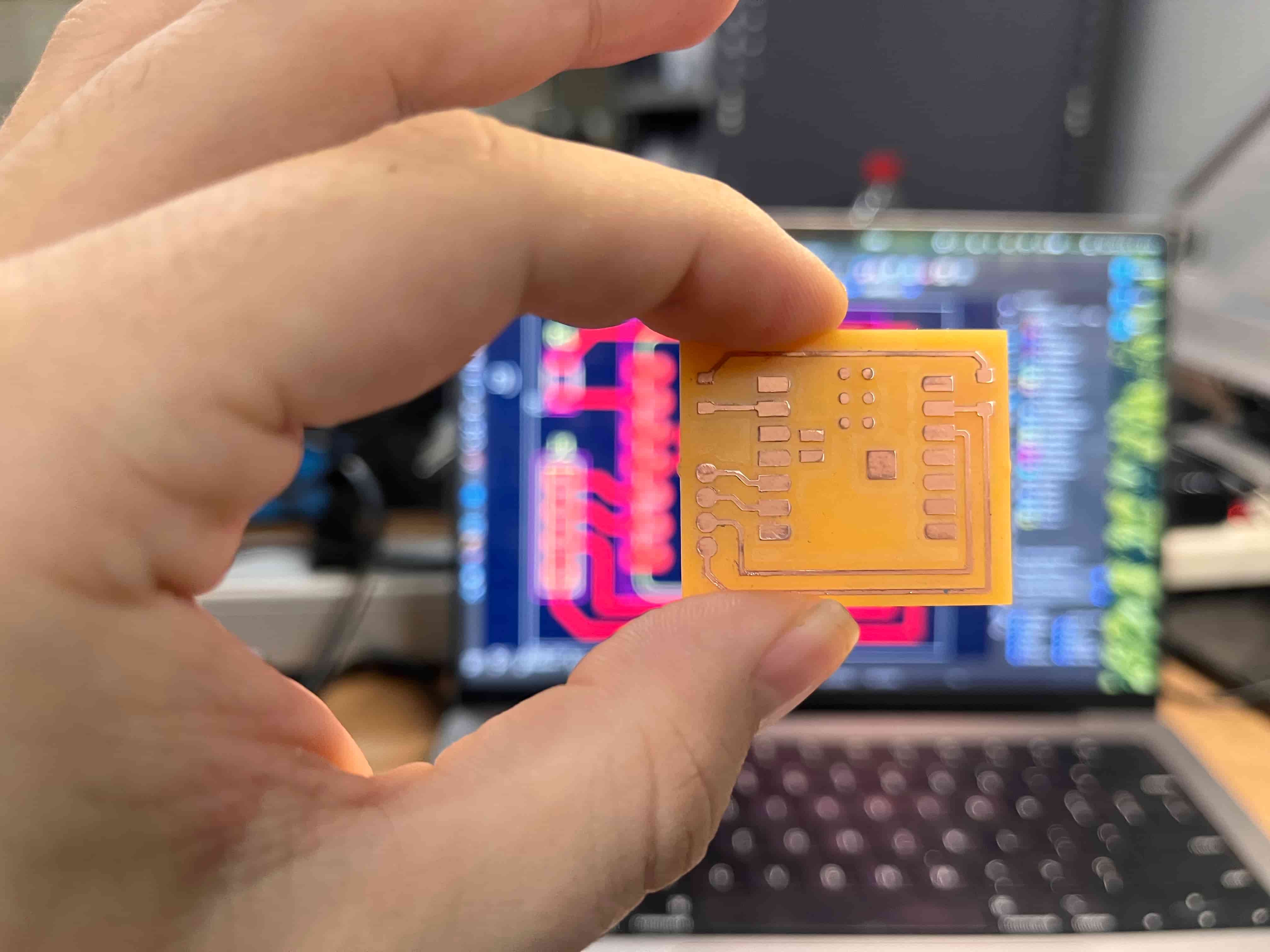
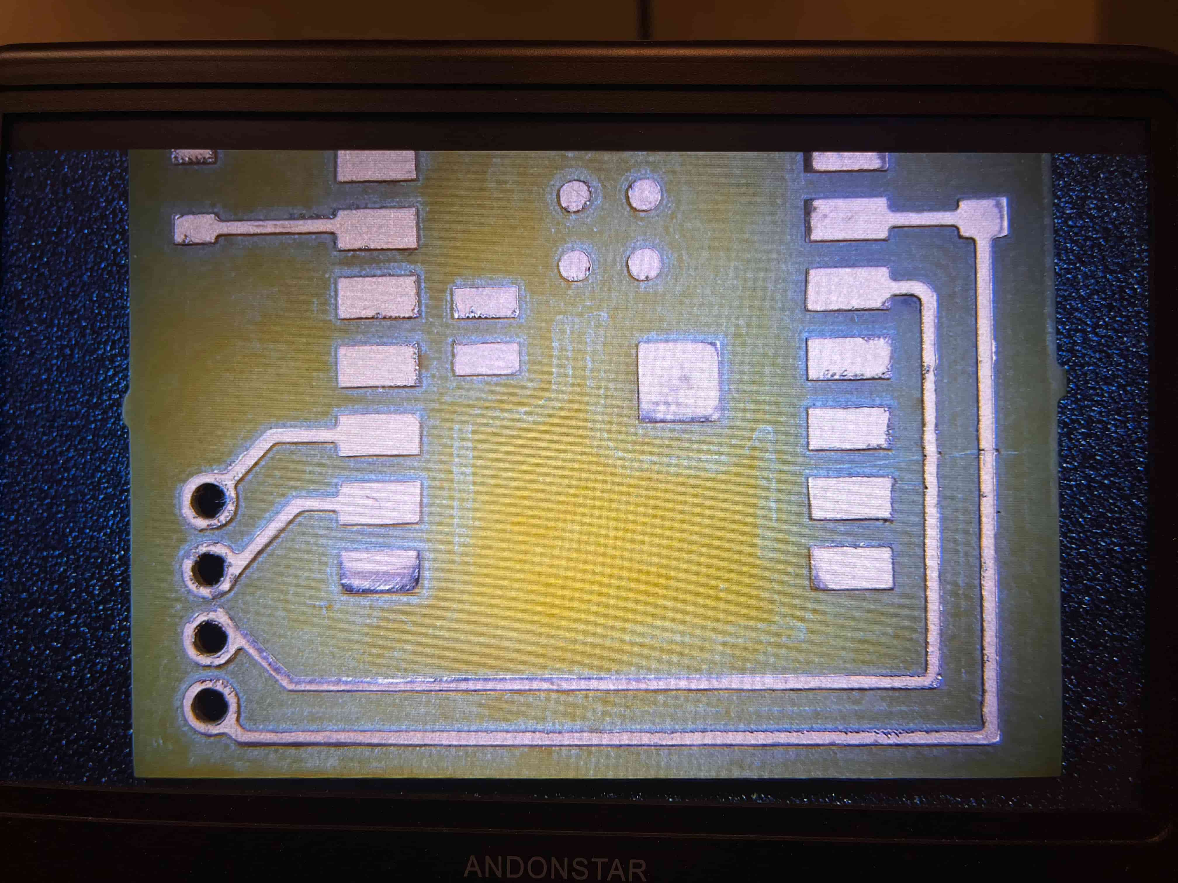
Oh well. Back to the drawing board! I went through the process again, this time making sure the milling machine showed the holes in 3D. Then milled, sanded, polished, etc and even checked it under the microscope to make sure everything looked good. All seems well, so I soldered on my components and moved on.
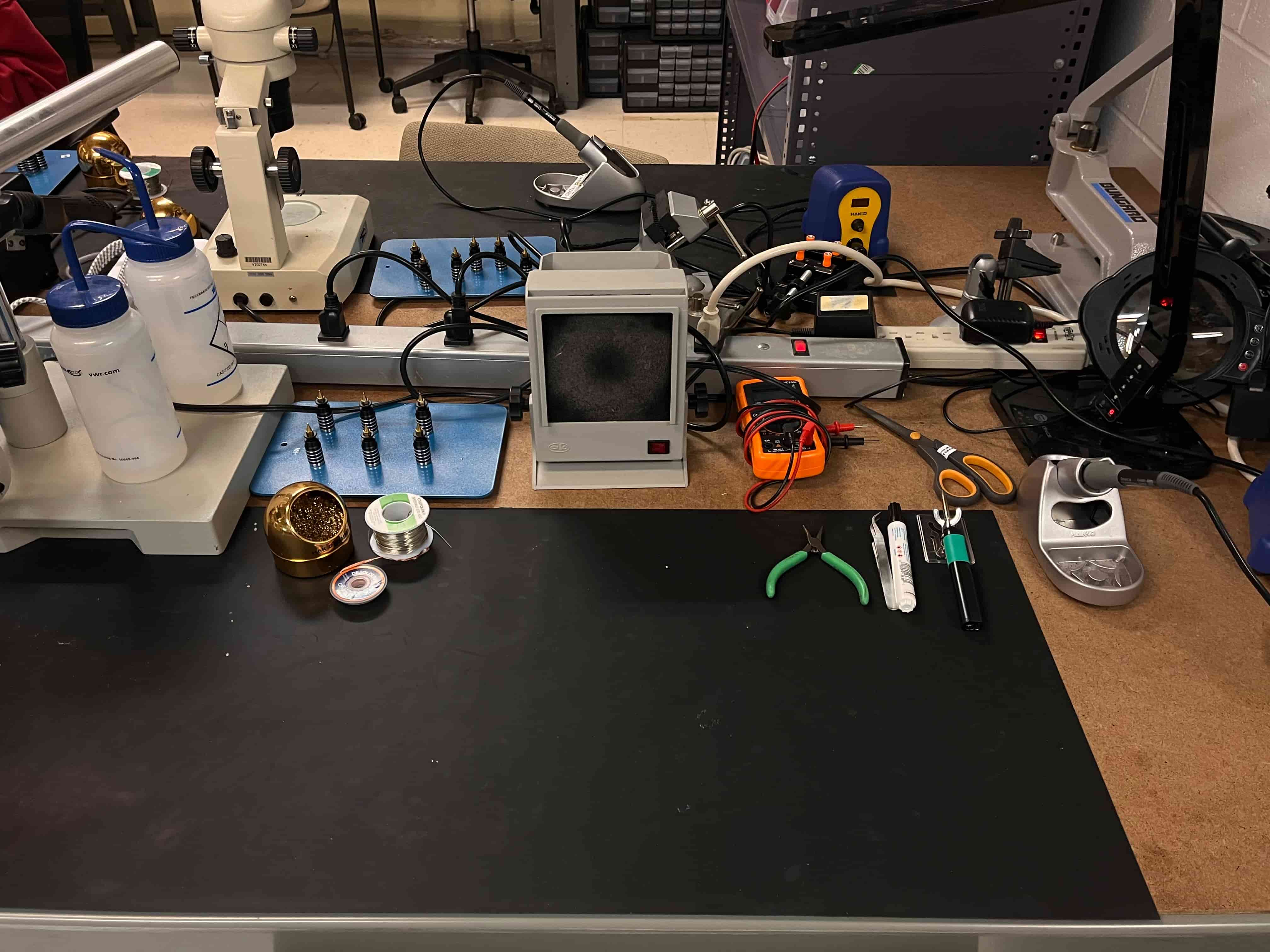
Make sure to clean up your station when you're done!
Testing the System
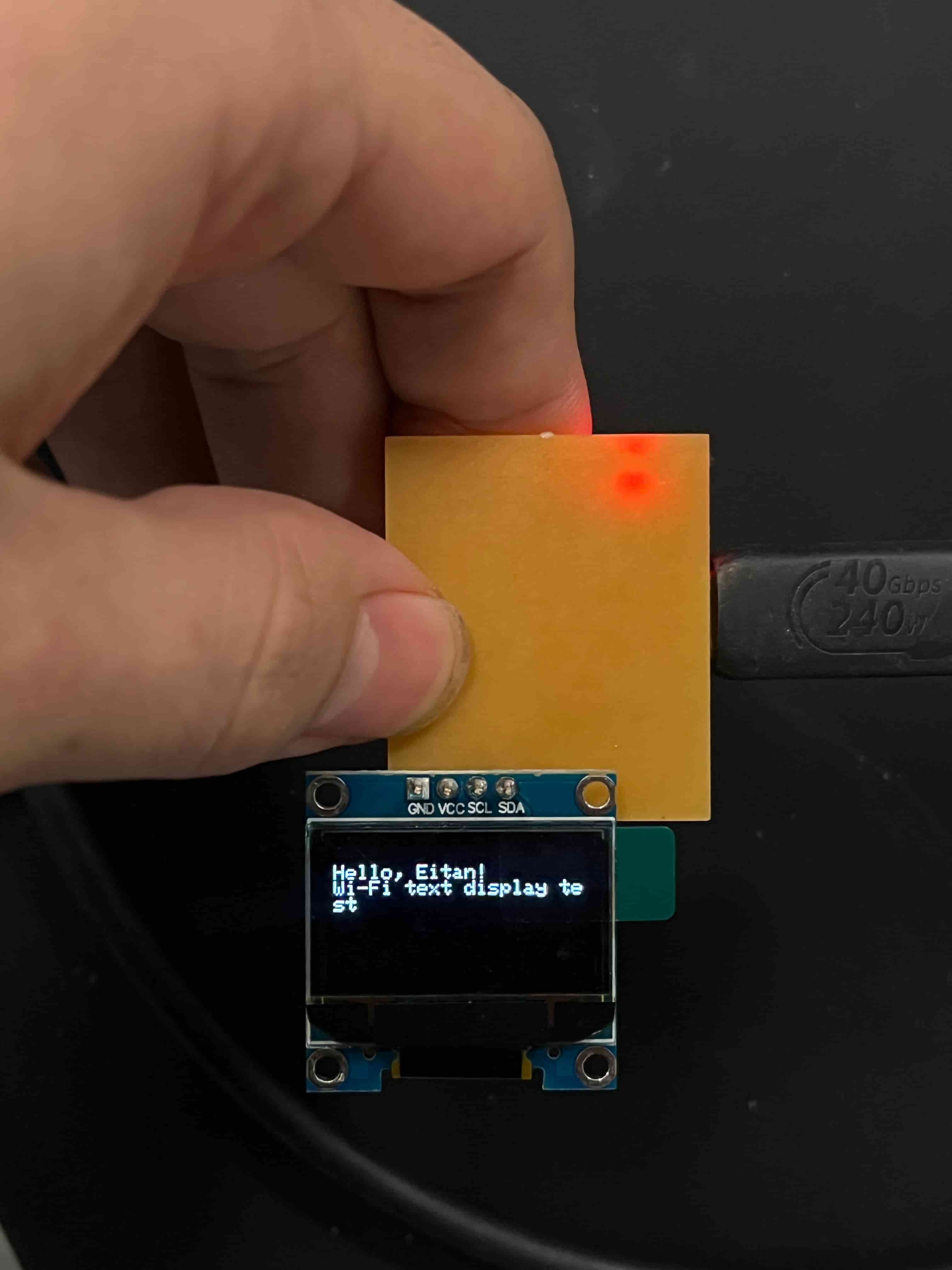
Now that I had the full board, I wanted to test the WiFI messaging capabilities! I used ChatGPT to generate some Arduino code, first just to test the LED and display to make sure everything was connected properly. You can find that code in the section above, or here.
That seemed to run perfectly, lighting up my LED and displaying the welcome message on my display.
It was time to start trying to send a message over WiFi. Once again, I employed ChatGPT to generate code for me, working through the errors until we found something that worked (included in the same conversation linked above). In the end, what seemed to work was signing up for an Adafruit IO account, through which I could include my account username and key within the Arduino code, and set up an attached feed through the Adafruit IO website that I could send messages from.
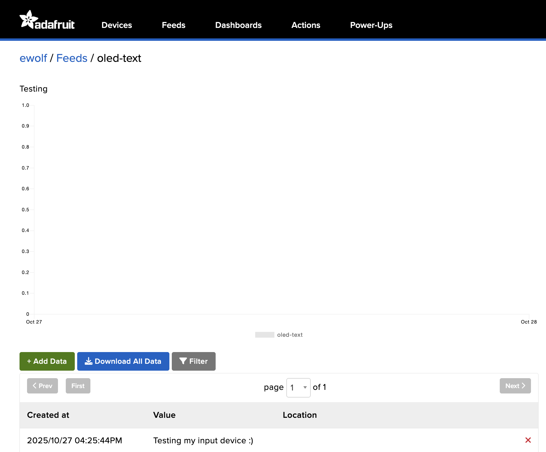
I typed in my message, and...
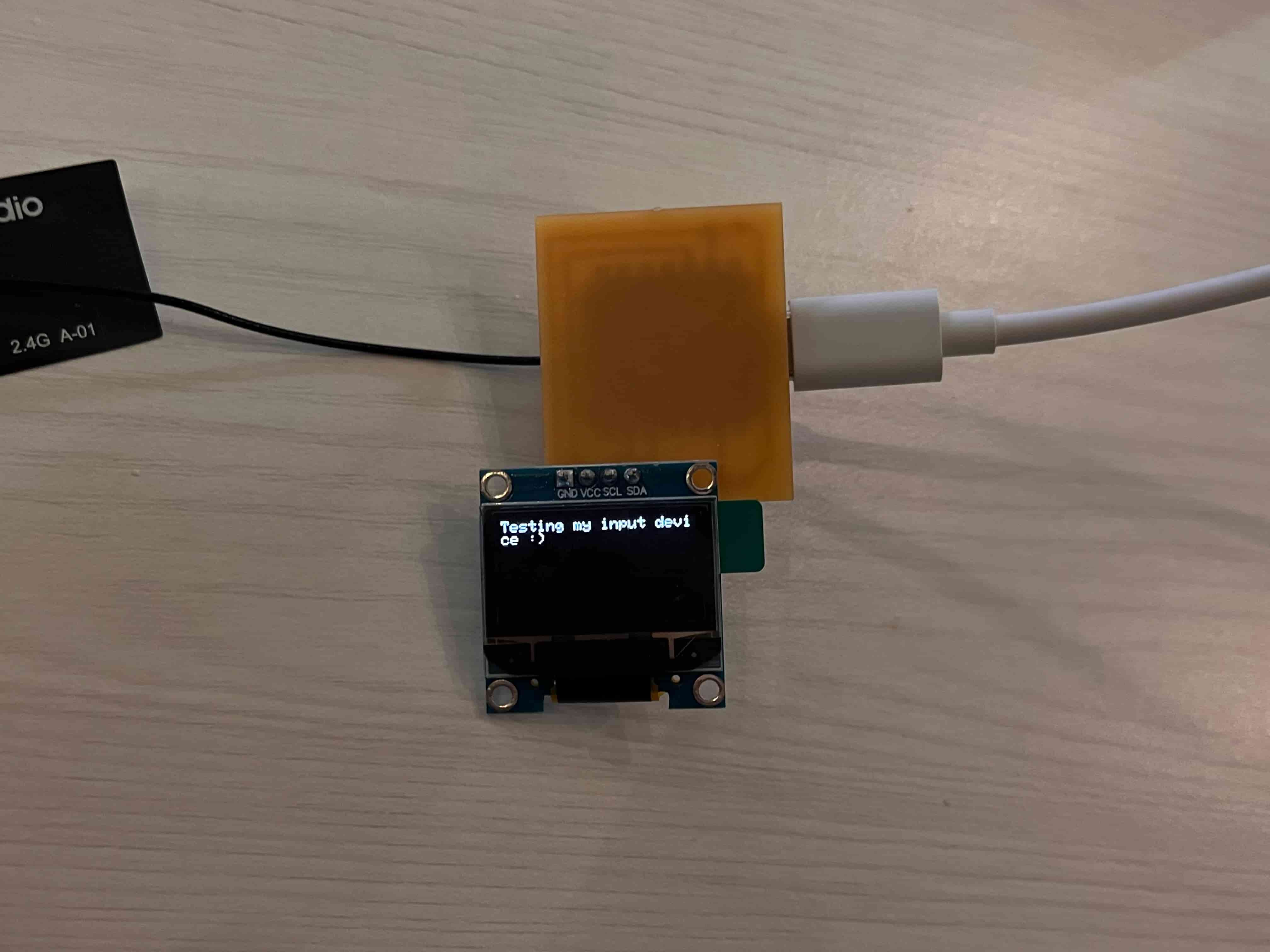
It worked!
I also used ChatGPT to generate a simple HTML interface I could use to communicate with the device, to test a better system for sending messages:
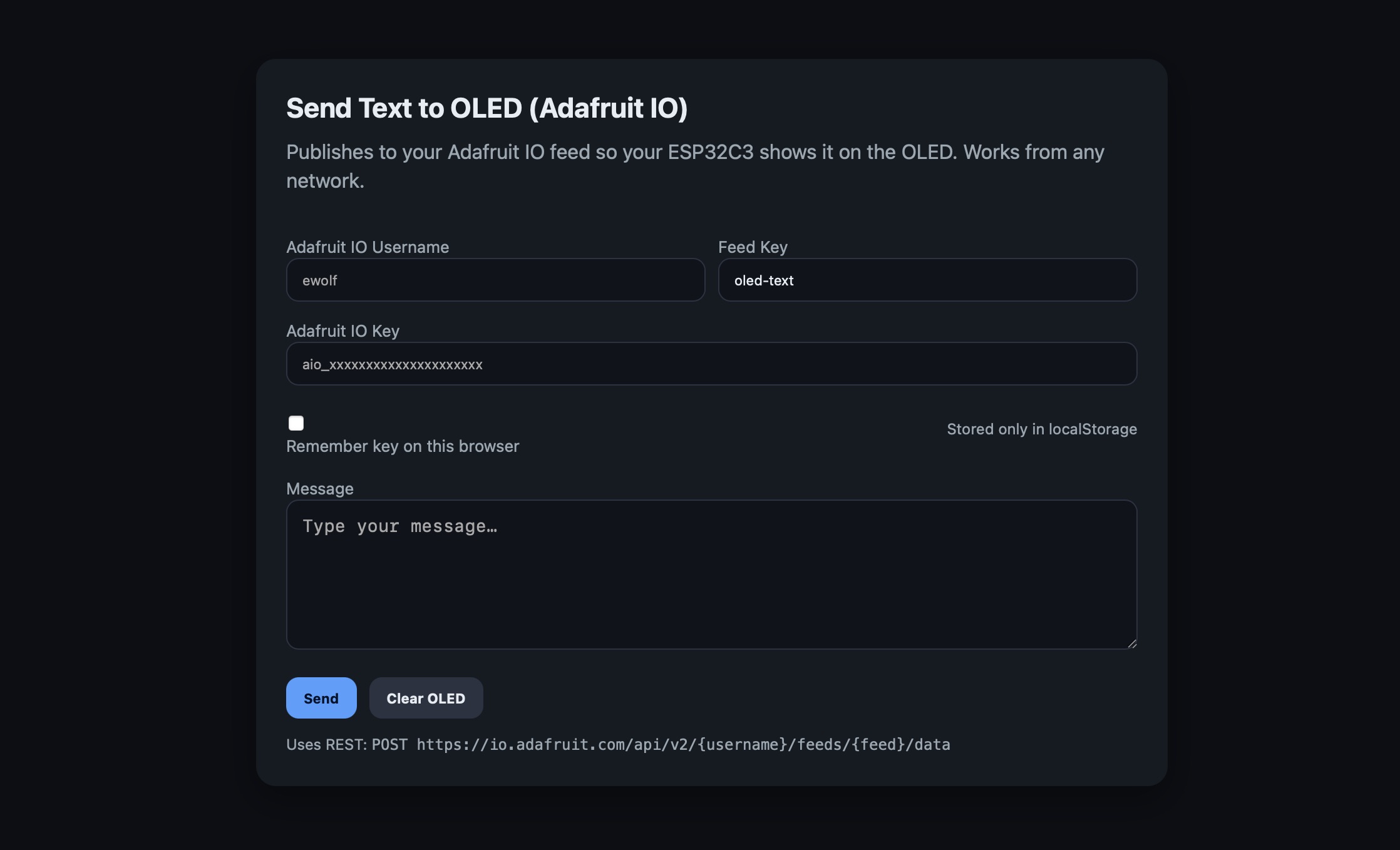
Looks great! Details on each of these in the section below.
System Details
I thought it might be helpful to break down what each of the Arduino programs attached above do, so with Claude's help I summarized each below. I used the prompt "Could you write a really quick, broad bulleted breakdown of what each of these do? I'm writing documentation and need some summaries on what each do, the difference between them, and how to use them". I hope this helps give a clearer understanding about what's going on under the hood, and what you'll need to run each program:
ESP32C3_LightAndDisplayTest.ino
Purpose: Basic hardware test to verify the OLED display and LED are working correctly before adding any networking features.
What it's doing: Uses I2C with pins D4 (SDA) and D5 (SCL) to interface with the OLED display at address 0x3C. Tests the LED on pin D1 with a 3-blink sequence at startup, then continuously pulses it on and off every 500ms in the main loop. Tests the OLED by displaying "Hello, Eitan!" and "Wi-Fi text display test" as confirmation that the display is functioning properly.
What you need: No configuration required—just upload and run to test your hardware.
How to use it:
- Upload the sketch to your ESP32-C3.
- Watch the LED blink three times at startup, then pulse continuously.
- Check the OLED display for the "Hello, Eitan!" test message.
- Open the Serial Monitor to see initialization messages and confirm the display is working.
ESP32C3_Wifi_Test.ino
Purpose: Local web server that lets you send text to the OLED through a simple HTML interface on your local network.
What it's doing: Connects to Wi-Fi using the provided credentials and creates a local web server accessible at the device's IP address or http://text-display.local/ via mDNS. Hosts a simple HTML page with a text box and two buttons—one to send messages to the OLED and one to blink the LED. When you submit text through the web interface, it URL-decodes the message, blinks the LED twice, and displays the text on the OLED with automatic word wrapping (approximately 21 characters per line). Handles three HTTP routes: "/" for the main page, "/msg" for receiving text, and "/blink" for LED control.
What you need: Wi-Fi credentials (WIFI_SSID and WIFI_PASS) configured in the code. Optionally, you can customize the mDNS hostname (default is "text-display").
How to use it:
- Fill in
WIFI_SSIDandWIFI_PASSin the code. - Upload the sketch.
- Watch the Serial Monitor for the IP address (or visit
http://text-display.local/if mDNS works on your network). - Open the page in your browser. Type a message and press Send → the LED blinks and your text appears on the OLED.
- Programmatic call:
http://<device-ip>/msg?text=Hello%20world - Quick blink:
http://<device-ip>/blink
- Programmatic call:
WORKING_SKETCH.ino
Purpose: IoT-enabled display using Adafruit IO's MQTT service to receive messages from anywhere with internet access.
What it's doing: Connects to Wi-Fi and then establishes an MQTT connection to Adafruit IO's broker at io.adafruit.com using your username and API key. Subscribes to both the raw feed ("ewolf/feeds/oled-text") and JSON feed variant to handle messages sent either through the Adafruit IO web dashboard or via their REST API. When a message arrives, it parses the content (extracting the "value" field if it's JSON format), blinks the LED twice as confirmation, and displays the message on the OLED with word wrapping. Includes automatic reconnection logic that attempts to reconnect to both Wi-Fi and MQTT every 3 seconds if either connection drops.
What you need: Wi-Fi credentials (WIFI_SSID and WIFI_PASS), Adafruit IO account with your username (AIO_USERNAME), API key (AIO_KEY), and a feed name (FEED) configured in the code. You'll need to create the feed "oled-text" in your Adafruit IO dashboard before running.
How to use it:
- Create an Adafruit IO account at io.adafruit.com and create a feed called "oled-text" (or customize the
FEEDvariable). - Fill in
WIFI_SSID,WIFI_PASS,AIO_USERNAME, andAIO_KEYin the code. - Upload the sketch.
- Watch the Serial Monitor to confirm Wi-Fi and MQTT connection.
- Send messages to your display from anywhere:
- Go to your Adafruit IO dashboard → open the "oled-text" feed → click "Add Data" → type your message.
- The LED will blink twice and your message will appear on the OLED.
- You can also send messages programmatically via Adafruit IO's REST API.
send_to_oled.html
Purpose: Standalone HTML page that sends messages to your ESP32-C3 OLED display via Adafruit IO's REST API from any device with a web browser.
What it's doing: Provides a clean web interface for publishing messages to your Adafruit IO feed without needing to log into the Adafruit IO dashboard. Takes your Adafruit IO username, API key, and feed name, then uses the REST API to POST messages directly to the feed. Includes optional credential storage in the browser's localStorage so you don't have to re-enter your API key each time. Features a "Clear OLED" button that sends an empty string to blank the display, and supports Cmd/Ctrl+Enter keyboard shortcut to quickly send messages.
What you need: Adafruit IO account with your username and API key. You'll also need the feed name (default is "oled-text"). The ESP32-C3 must be running WORKING_SKETCH.ino and connected to receive the messages.
How to use it:
- Save the HTML file to your computer and open it in any web browser (works offline once saved—no server needed).
- Fill in your Adafruit IO Username, Feed Key (e.g., "oled-text"), and Adafruit IO Key.
- Optionally check "Remember key on this browser" to save your credentials locally.
- Type your message in the text box and click Send (or press Cmd/Ctrl+Enter).
- The message will be published to your Adafruit IO feed and appear on your OLED display within a few seconds.
- Click Clear OLED to send an empty message and blank the display.
- Check the status area below the buttons for confirmation or error messages.
3D Printed Case
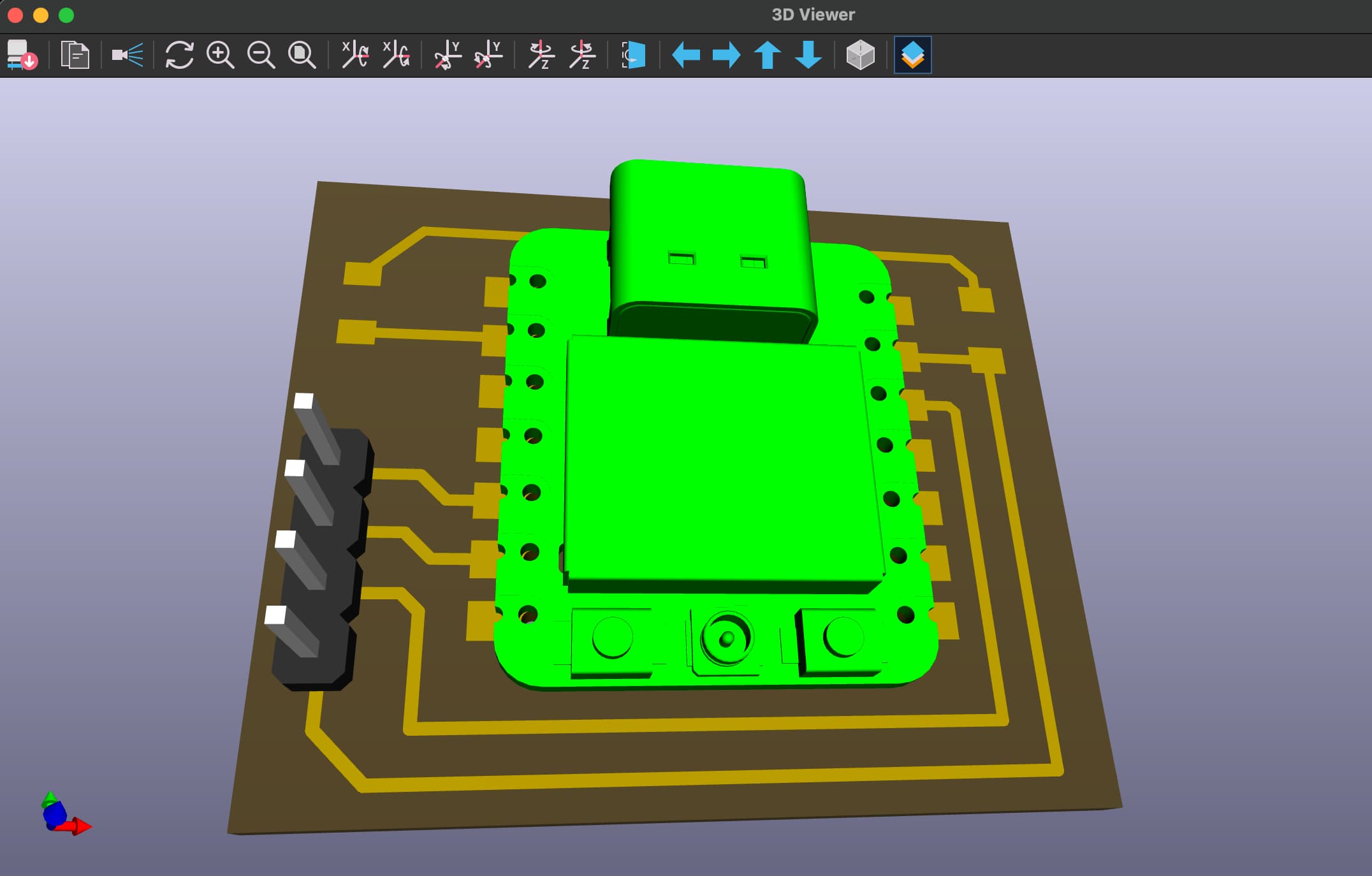
I also wanted to try making a 3D-printed case for my build this week. I was able to find a 3D model of the ESP32C3, and import it into KiCAD to combine with the connector I was using; then export those into Fusion360 to model around:
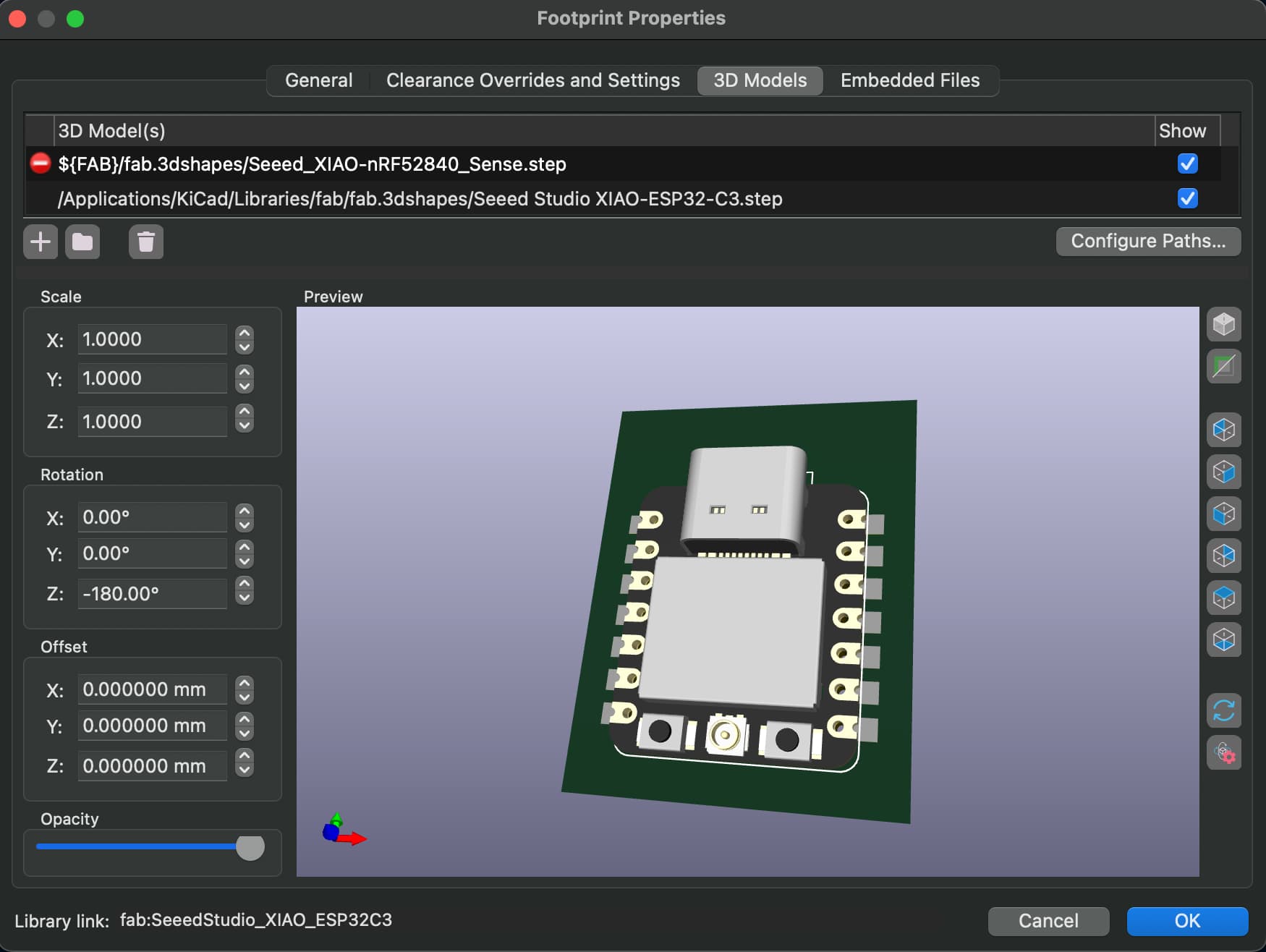
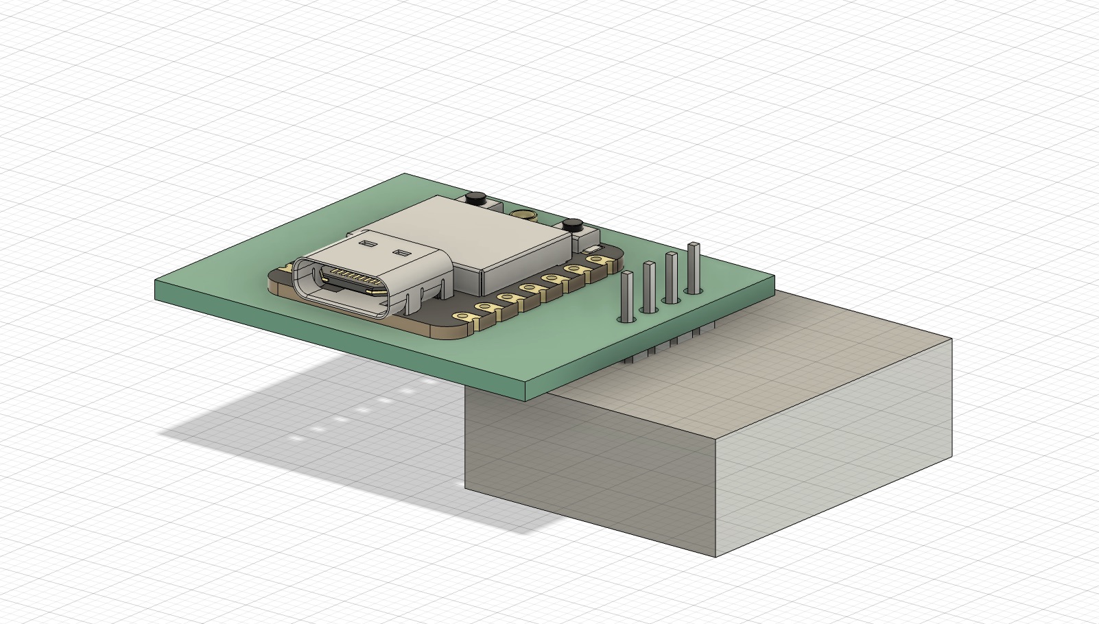
Here's what it looked like imported into Fusion360 (attached to a placeholder box to represent the board):
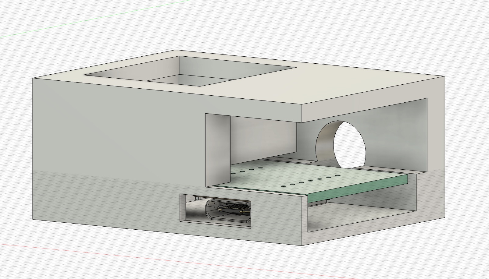
And here's the designed model! I left holes for the USB-C connector and the WiFI antennae:
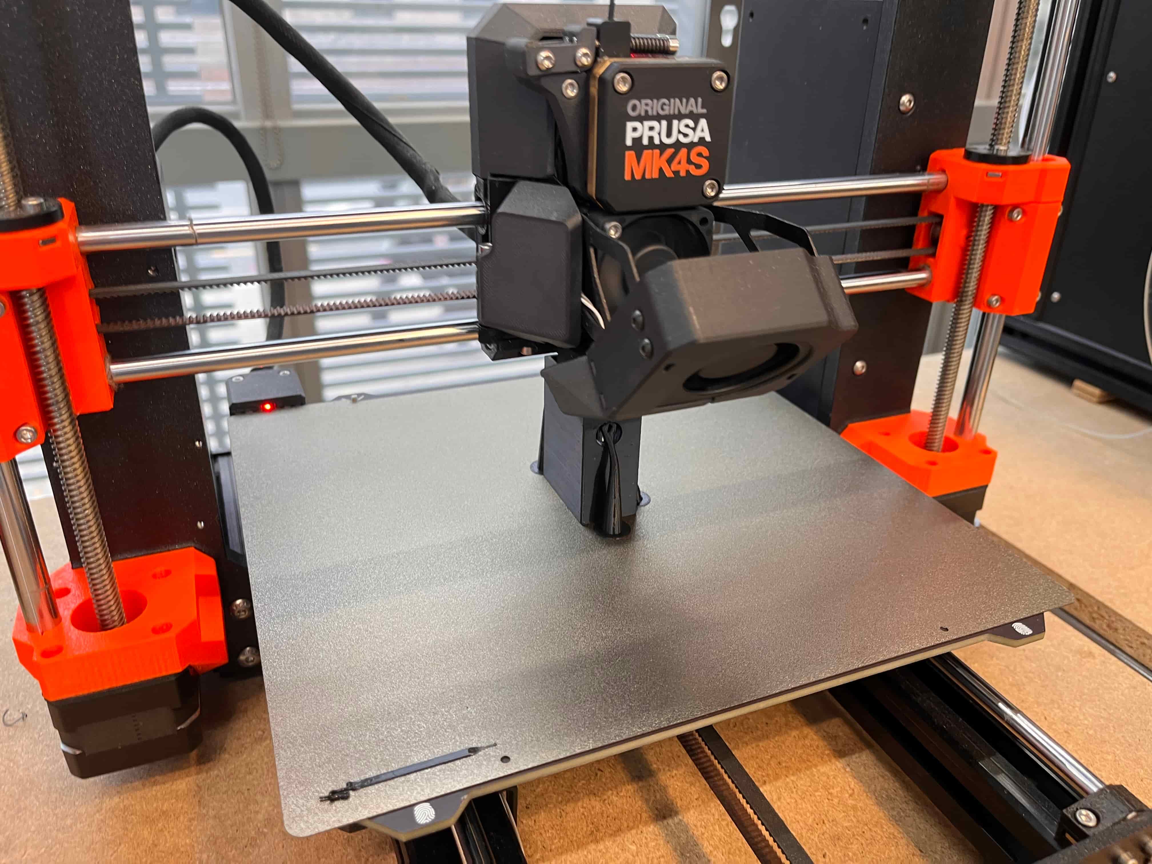
Then I printed it out on the Prusa, and cut off the supports:
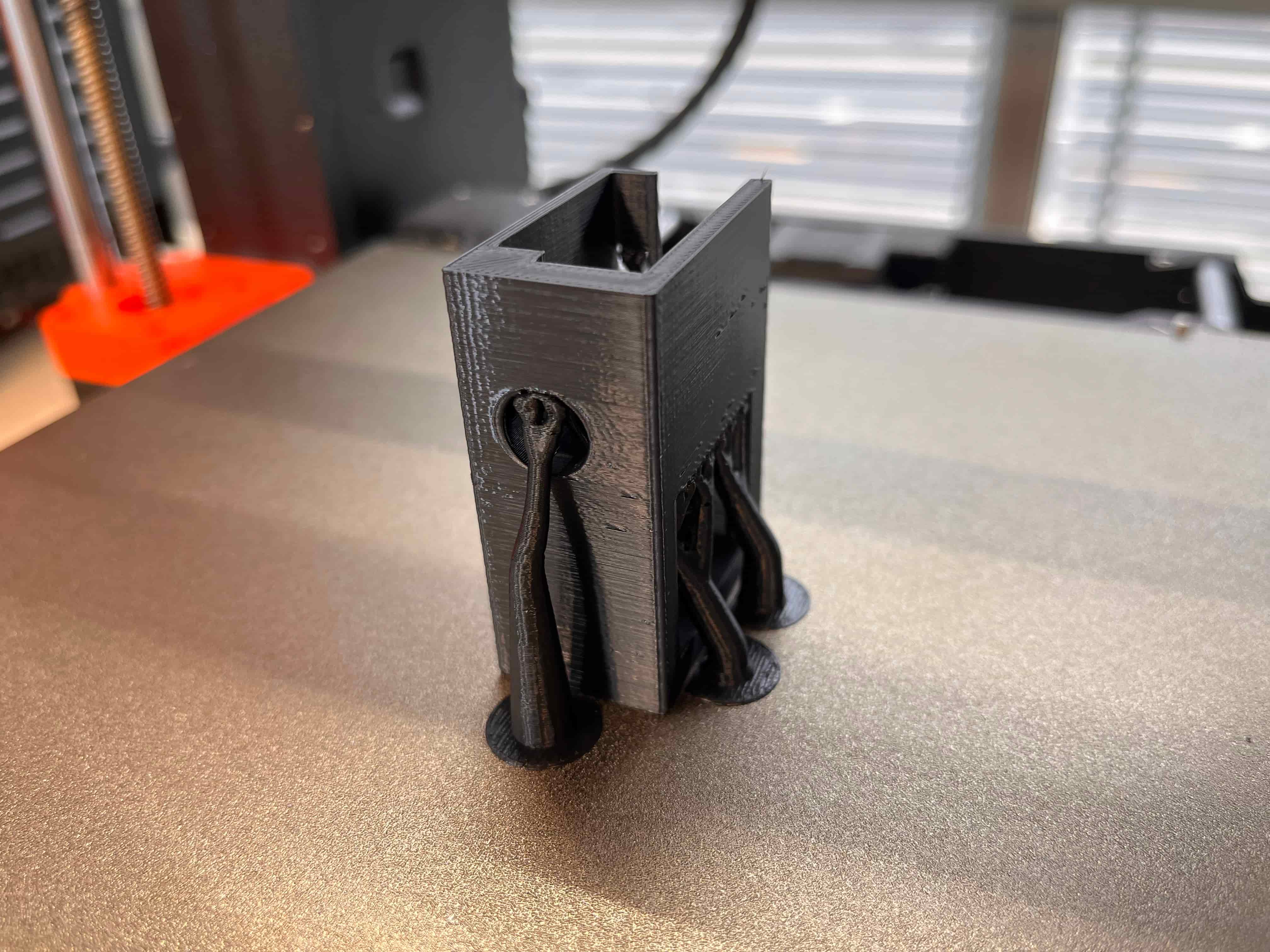
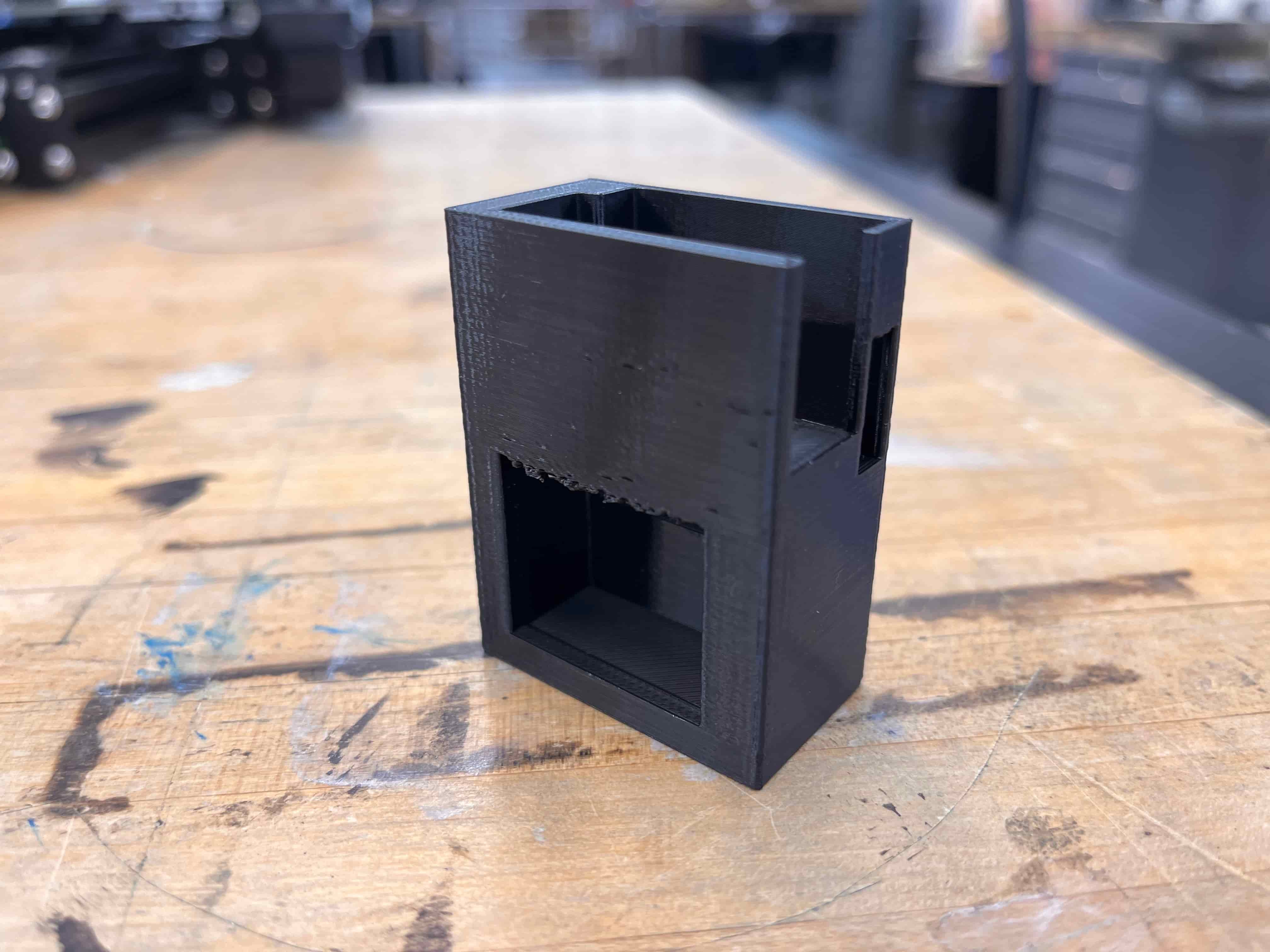
Unfortunately, with the way I designed this housing, the chip/PCB couldn't actually slide in – but that's ok! We live, we learn, we try again. I wasn't able to snap a photo of it in time, but I think I was really close; I just have to remember to think through what everything will take to get in and stay in, rather than design around the PCB assuming it's already encased.
Final Thoughts
I'm really excited about this week, because this is pretty directly related to what my final project will need to do. I think this code and system will act as a great foundation to my final project, but instead of displaying on a screen, the message will *ideally* print out... I'm also excited to try designing another 3D-printed housing next time around.
More to come soon – see you next week!