Document a final project masterpiece that integrates the range of units covered, answering:
What does it do? ✓
Who's done what beforehand? ✓
What sources did you use? ✓
What did you design? ✓
What materials and components were used?/Where did they come from?/How much did they cost? ✓
What tools and processes were used? ✓
What questions were answered? ✓
What worked? What didn't? ✓
How was it evaluated? ✓
What are the implications? ✓
Prepare a summary slide and a one minute video (optional) showing its conception, construction, and operation ✓
Your project should incorporate 2D and 3D design,
multiple additive and subtractive fabrication processes,
electronics design and production,
embedded microcontroller design, interfacing, and programming,
system integration and packaging
Final Project
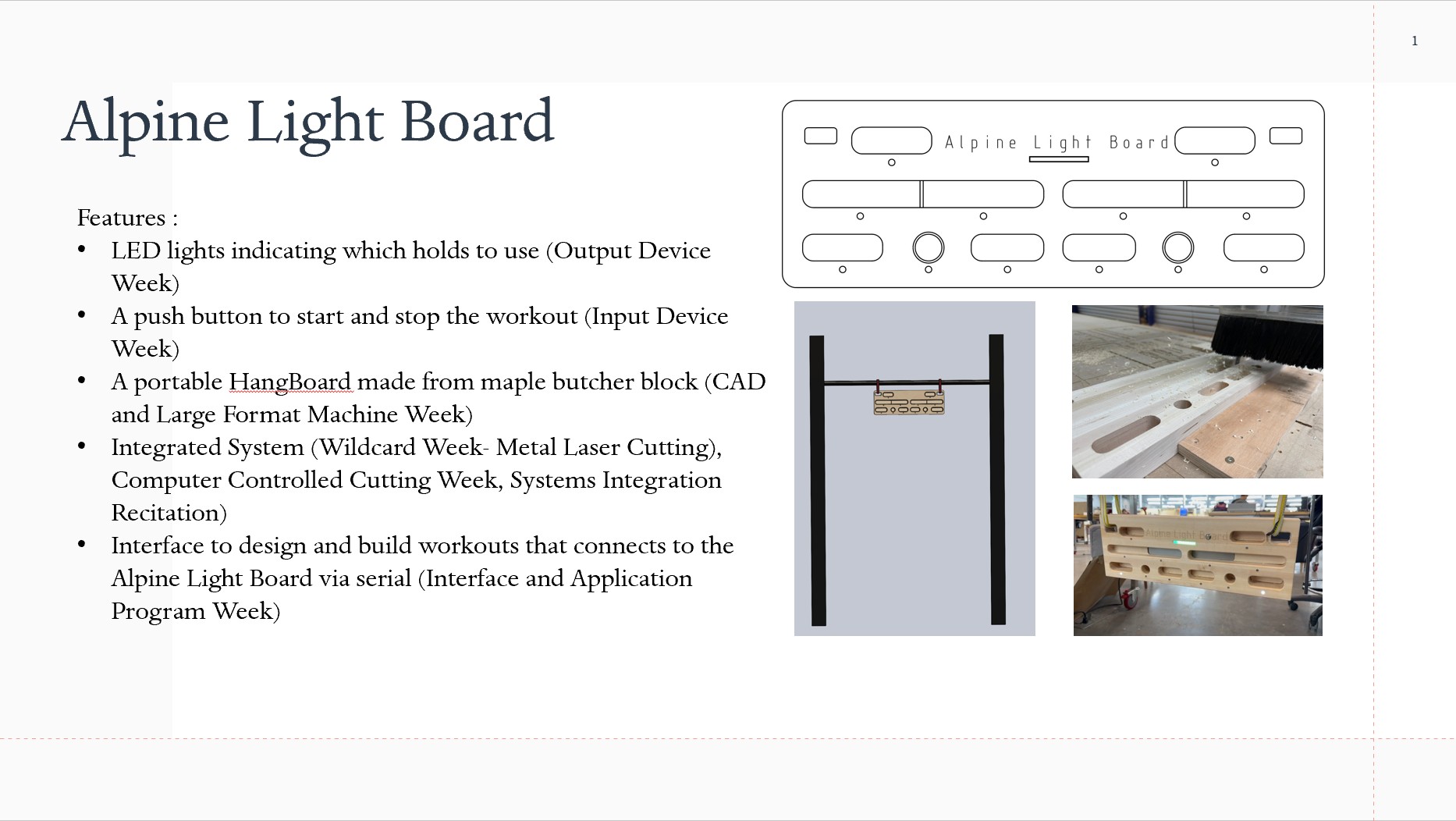
Idea: Smart HangBoard (Alpine Light Board)
A rock climber's ideal training partner is a SMART hangboard. It includes LED lights indicating which holds to use, a load sensor-activated timer, and a mobile app for programming and tracking workouts.
Additionally, an AI app can suggest hangboard routines tailored to your climbing level and past workouts.
The hangboard easily attaches to your backpack, making it convenient for approaches, so you can use it to warm up
for your toughest climbs.
Summary Slide as presented on 15 December
What Has Been Done Before
Climbro developed a wall-mounted hangboard with interchangeable holds and an AI powered personal trainer. Additionally, the board has the ability to evaluate finer strength....but it is not clear what tech they are using to evaluate finger strength.
Moon Boards are a standardized climbing wall controlled by an app. Anyone can download the app, connect to a Board via Bluetooth, and try different climbs or create their own. In order to know which holds to use
different colored LEDs turn on to identify the start, end, and all the holds in between. A few other companies have jumped on the LED Climbing Wall trend such as
Tension Climbing and Kilter
Finger strength training by using a hangboard is prevalent in the climbing community with lots of different hangboards on the market. Hereis a link to a review of The Best Climbing Hangboards of 2025. My husband and I have the Porblem Solver Hangboard and Metolius Project hangboards
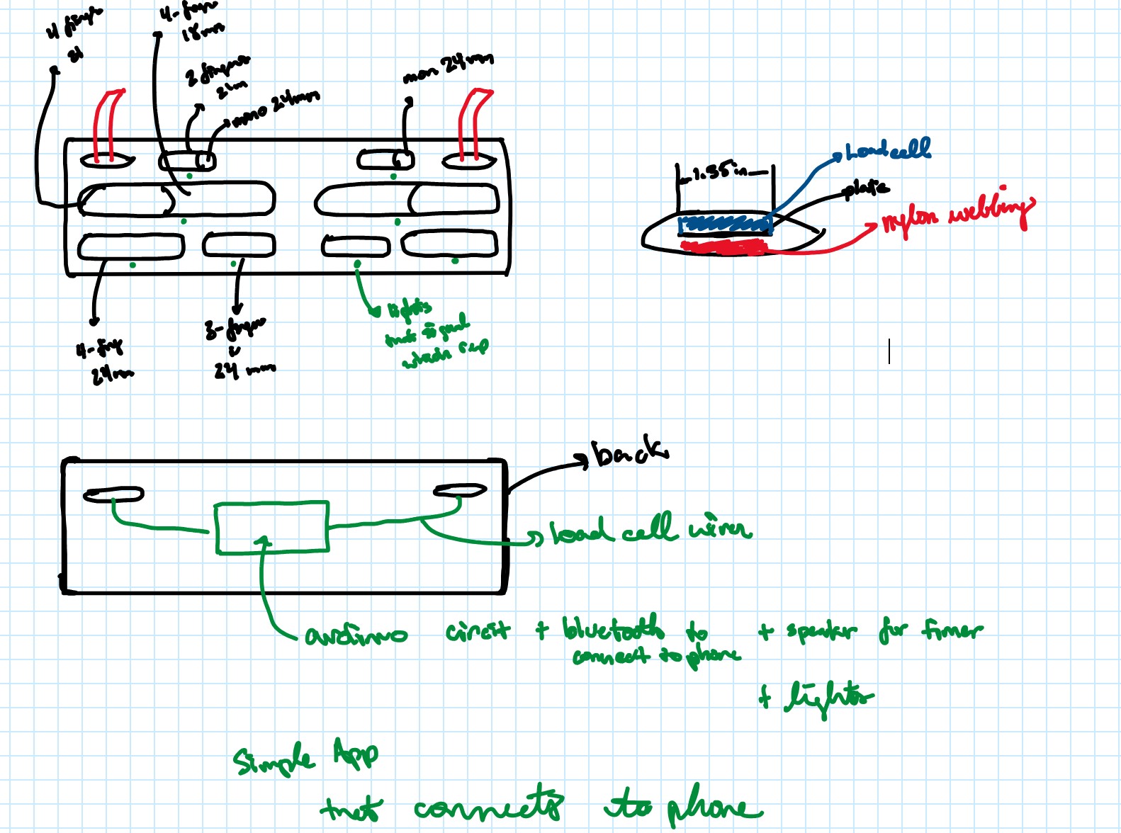
Initial Concept
Looked at Two Stones HangBoard to get an idea for dimensions
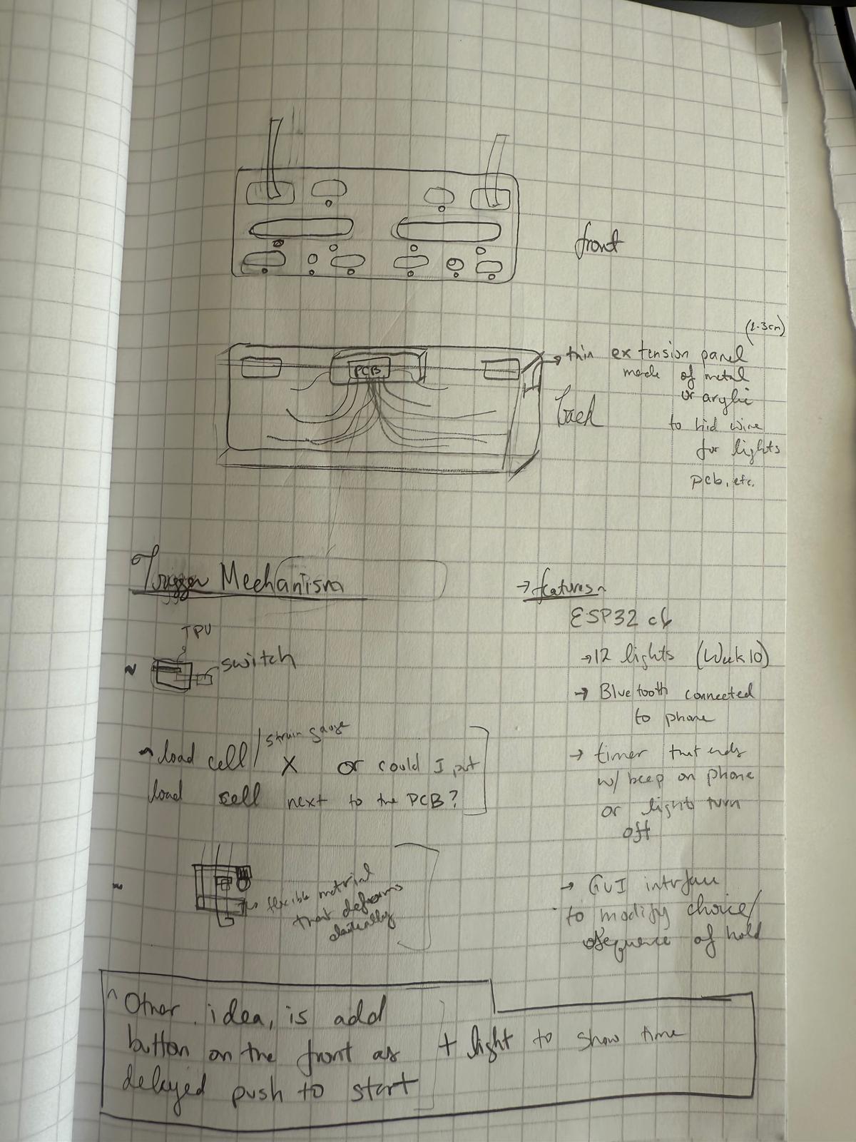
I used oneNote to sketch out some ideas.
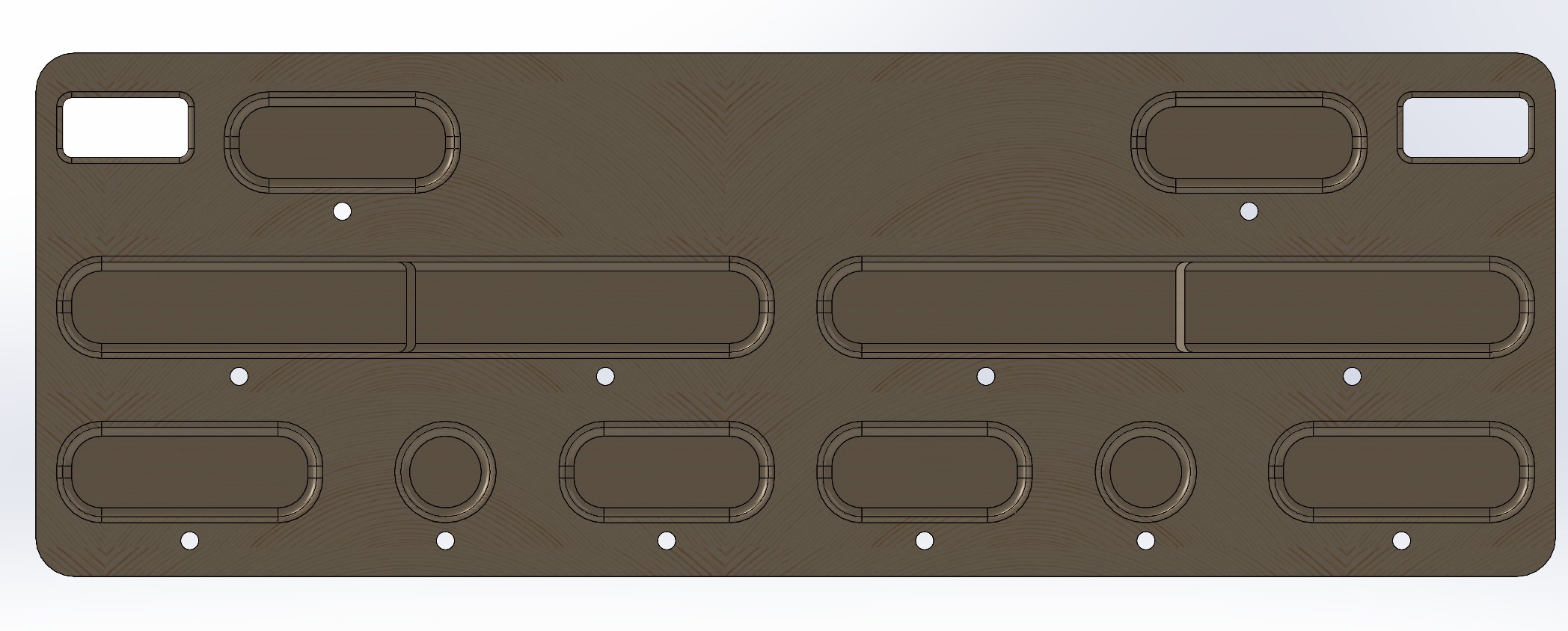
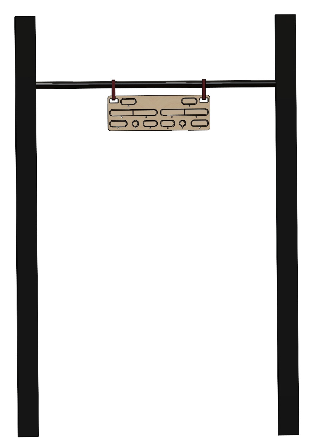
Solidworks Models
The Hangboard
This hangboard features a variety of hold sizes ranging from 18mm to 30mm, with a 35mm mono.
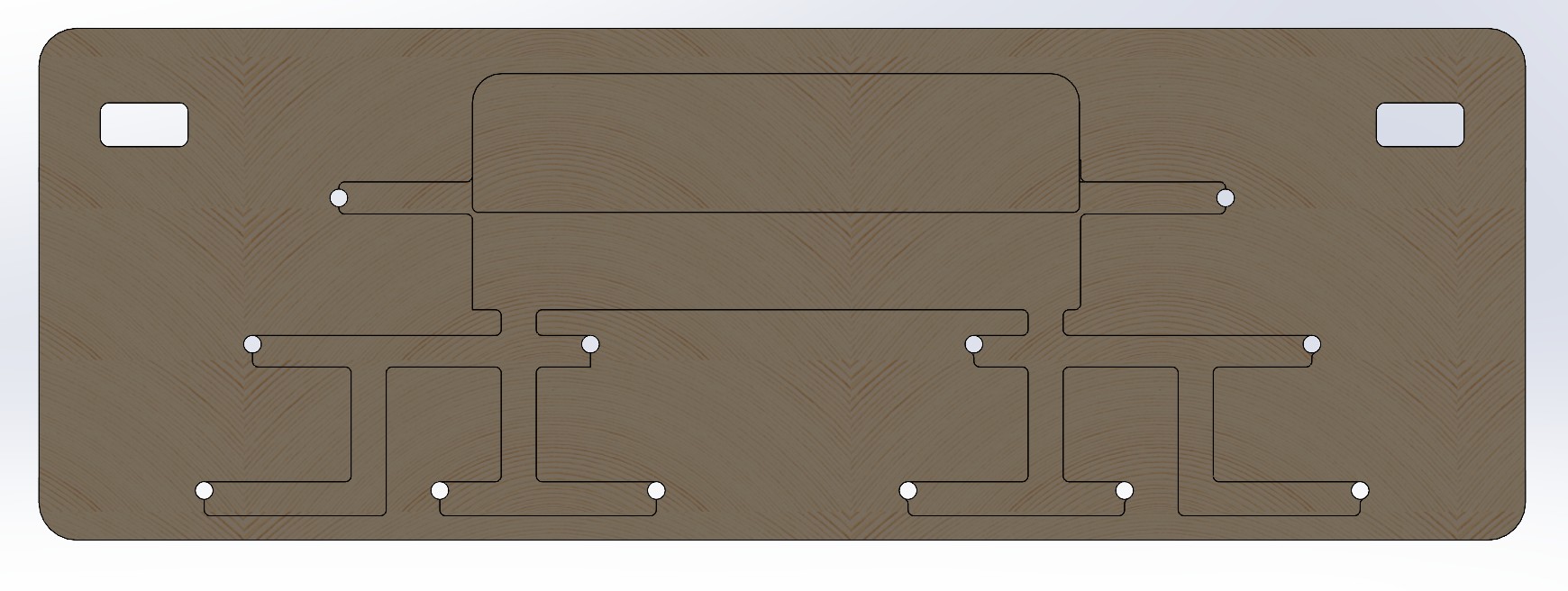
Back of the Board
The System
Dimensions:
The hangboard can be mounted on a pull-up bar or a sturdy horizontal tree branch.
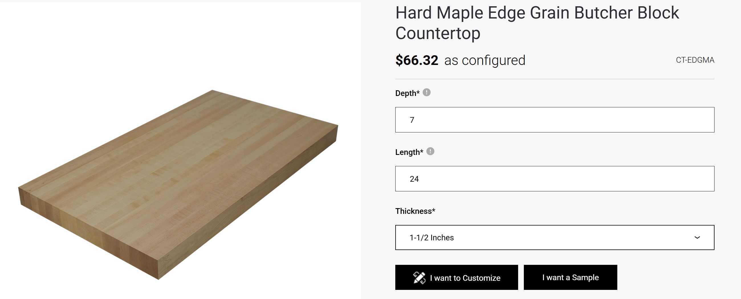
What type of Wood? I read this blog
to get an idea of what type of wood to use. They recommended either beech, birch, oak, or another hardwood.
I found a butcher block of Hard Maple Edge Grain and ordered two. Unfortunately, the butcher blocks will not arrive until 24 October.
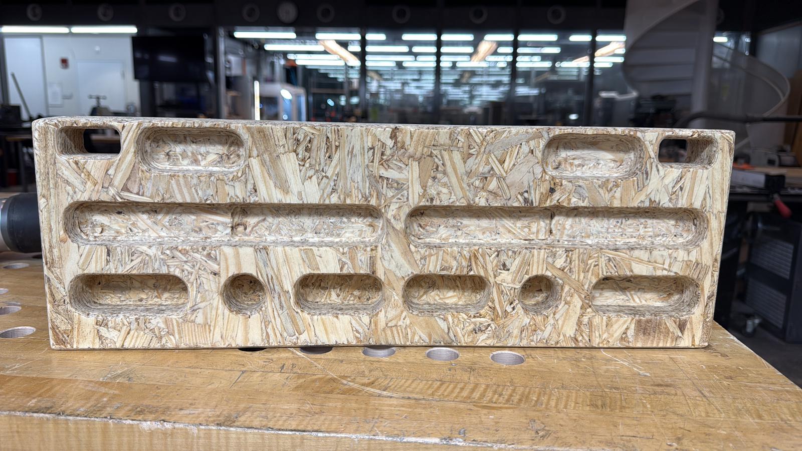
The butcher block arrived on 16 October, 2025 during Computer-Controlled Machining Week. My goal is to characterize the alignment, runout, fixturing, speeds, feeds, and CAM path for the Shopbot on OSB
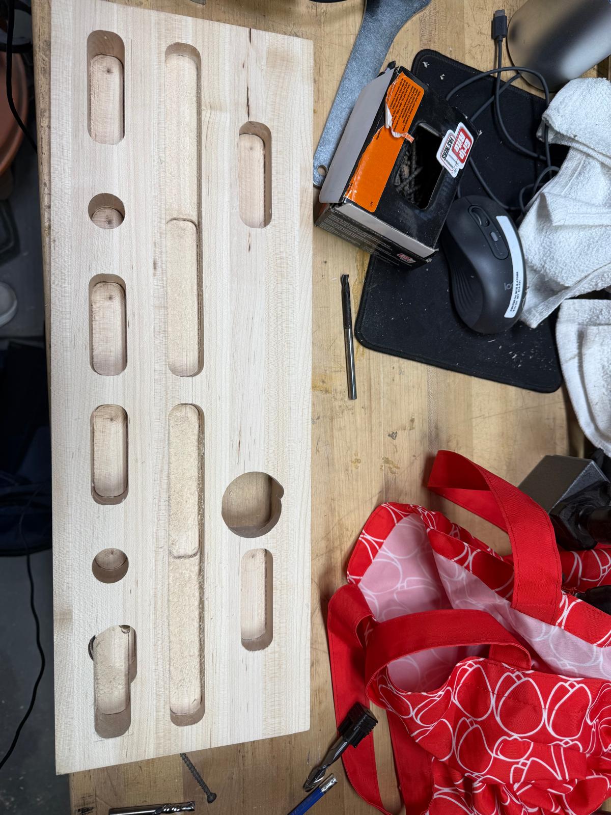
Overall, the first prototype turned out well! However, the zero shifted a little bit in the +y-axis which I didn't catch until it was too late. In the future, maybe I want the first cut to be the bottom right edge fillet.
Prototype 2
Design Updates:
-A few small design updates. I decreased the width of the holds from 30mm to 25mm,
in order to allow for more clearance at the top.
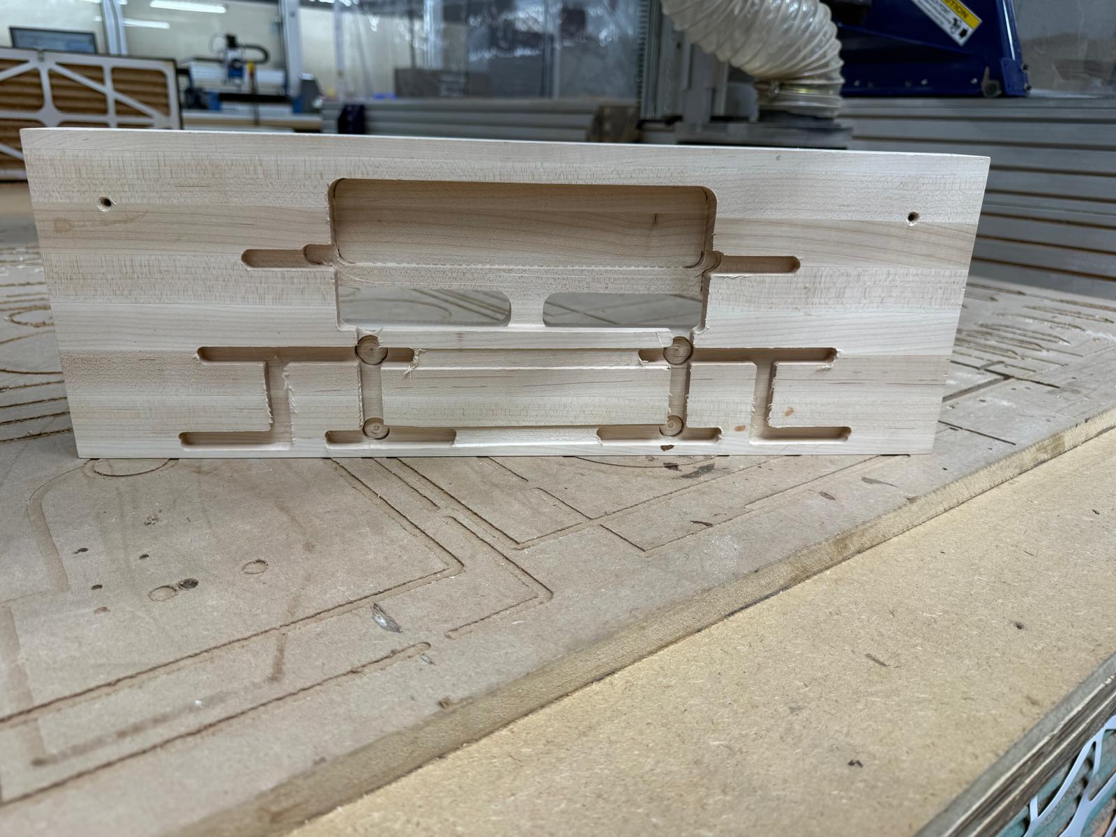
-Added pathways to the back of the board to route wires
Machining the Board (Skills from Week 7):
Every each time I use Fusion, it always feels like my first time. Originally, I used Adaptive Clearing for the pockets and a ¼-inch diameter flat-end mill. I followed the same speeds and feeds I used to machine the OSB Hang board in week 7 (big mistake, I will get to that in a moment). Simulations also looked great!
I thought it would be simple to machine the board, especially since I had done it in week 7.
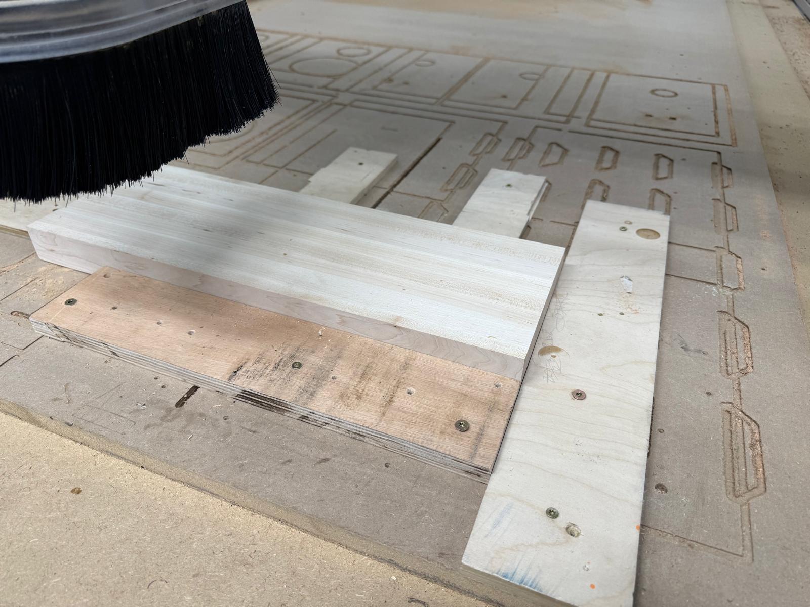
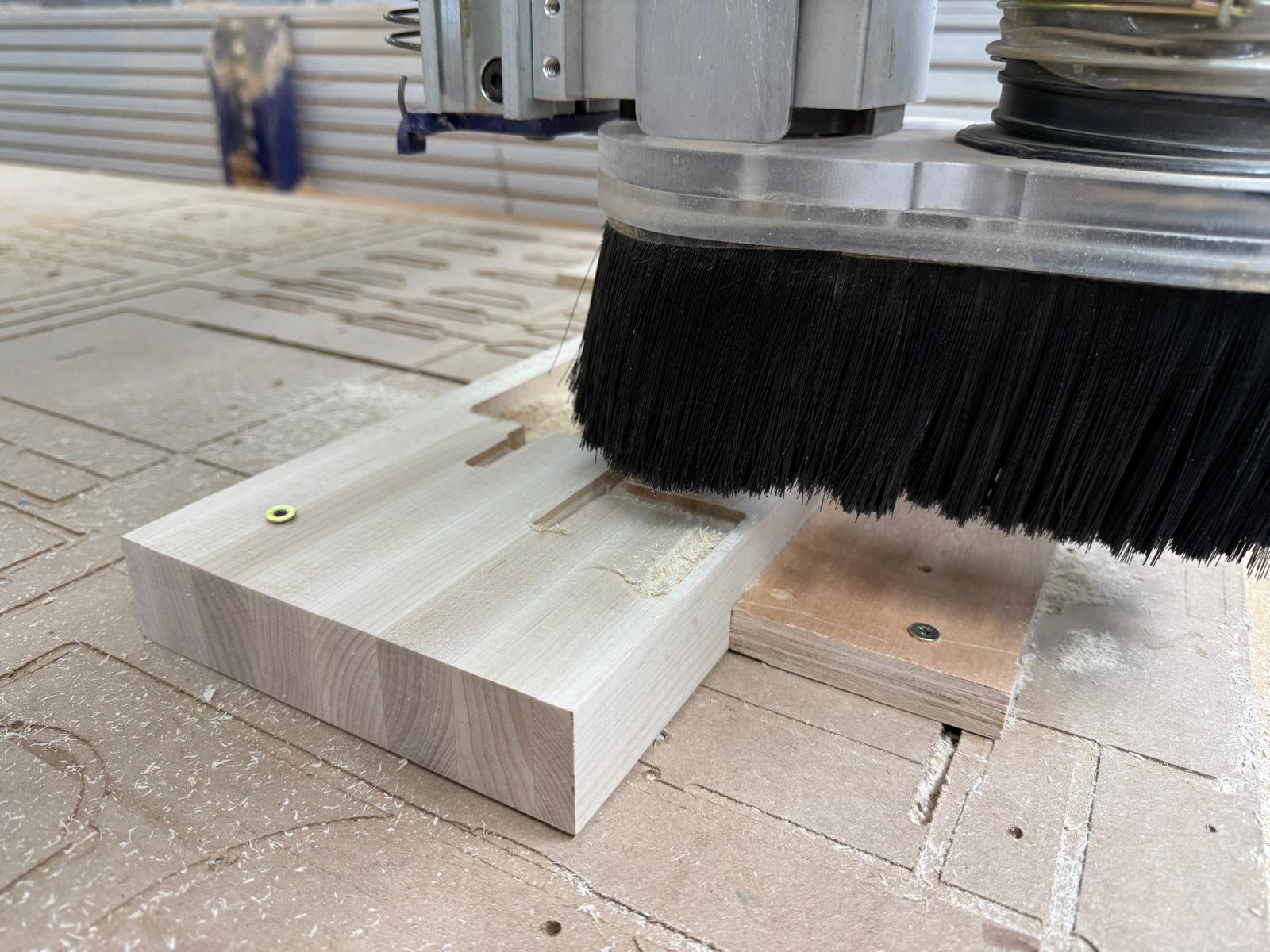
First, I secured the board using some scrap wood.
Picture: Initial Set-Up
Then I changed the collet for the ¼-inch endmill, set up my zero, and pressed start.
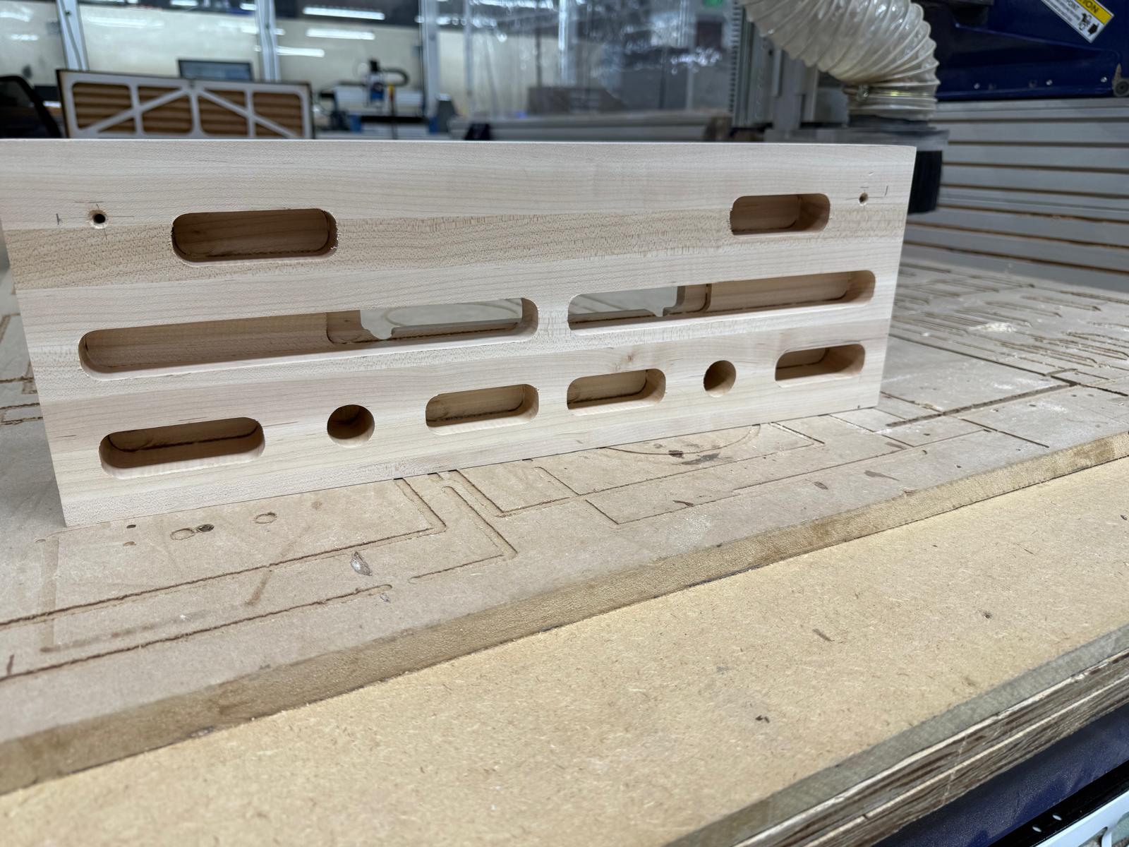
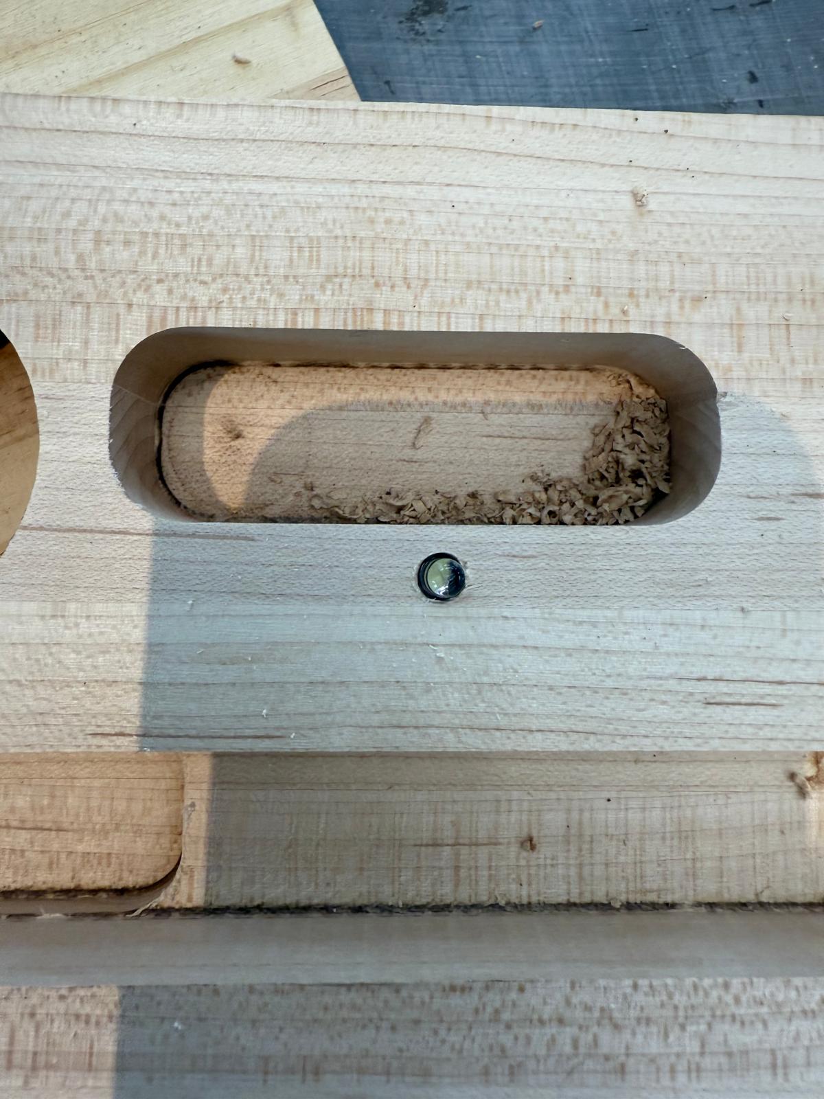
Things were going smoothly, then they weren’t. The wood started smoking and the board lifted,
so I pressed the emergency stop. It burned a hole through the board. Alfonso suggested I use a
larger endmill (1/2 in) and try again. The next problem was that the endmill was chattering, and
my zero was off, making everything slightly inaccurate. Dan suggested I use multiple step-downs
to avoid chattering. So rather than going all the way to the bottom of the pocket in one go, it
would cut in increments of .25 inches.
Prototype 2: Lots of lessons learned
Prototype 3
To better secure the board, I decided to put screws in the board.
New Board Set-Up
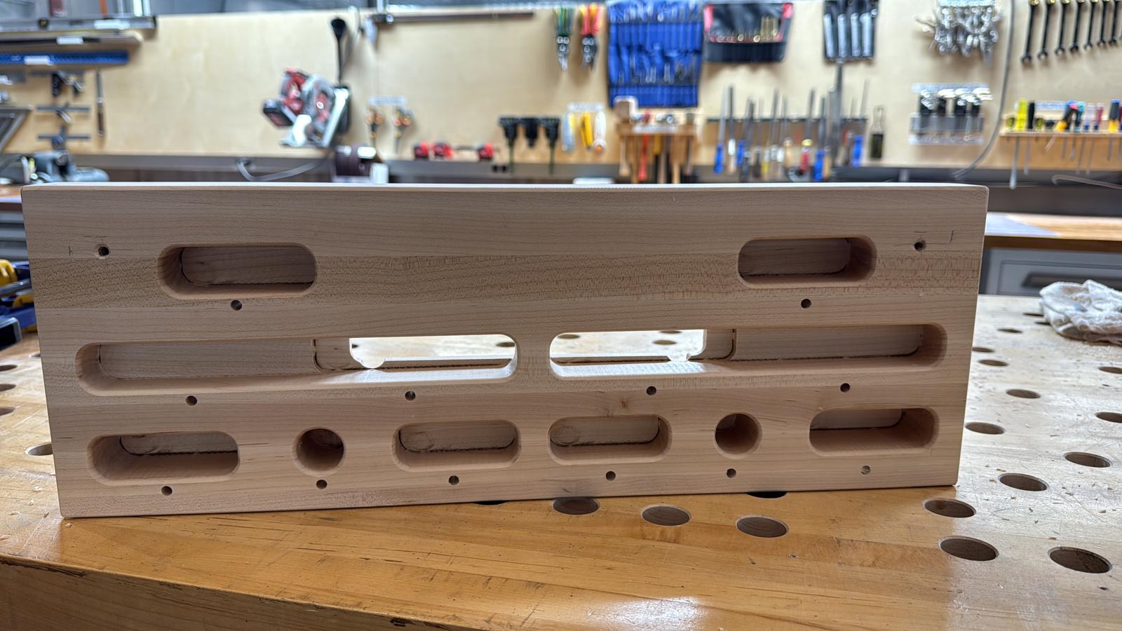
Front Complete
Back Complete
I still have a lot of post-processing to do. I plan to do the fillets shown in the schematic by hand, drill the holes for the lights and hang holes with a drill press, and laser-cut plates for the center hole backing
Post-Processing Complete
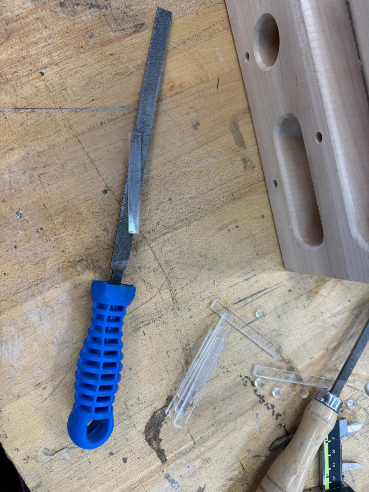
Holds without a Filet
I used a router to add 3mm filets to the holds and the edges of the board
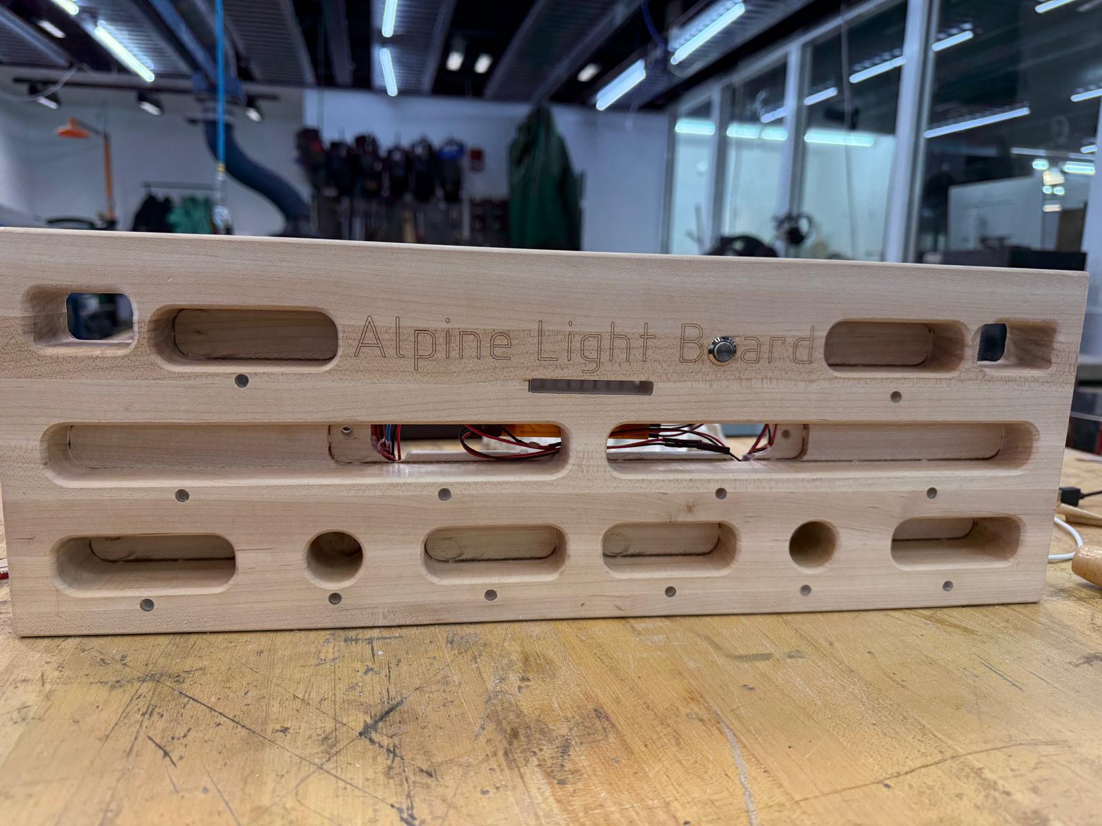
Laser Name
I designed a logo in Adobe Illustrator and Laser Engraved in using the X3 XTool laser. I used some other wood to kinda get
Shopbot to Finish up the Rest of the Cuts/ Laser Cut and Press fit roughed Acrylic
I used a 1/4inch endmill for the slots and used an 1/8 in endmill for small pocket
Electronics Design
Sketch and design goals.
Click Here for more details about the initial PCB design during Week 5 and different electronics components and features. Week 6 had a lot of growth and only successfully got a LED to turn on and powered it via battery.
Click Here for more progress made during
Week 8 and Week 9. Overall in week 8, successfully got a button turning on/off led, battery integrated, and load cell measuring strain.
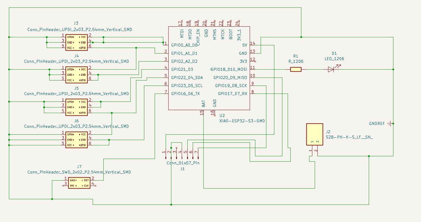
Week 9 PCB schematic featuring the lights for the holds, switch, and non-bluetooth speaker(wasnt able to make work):
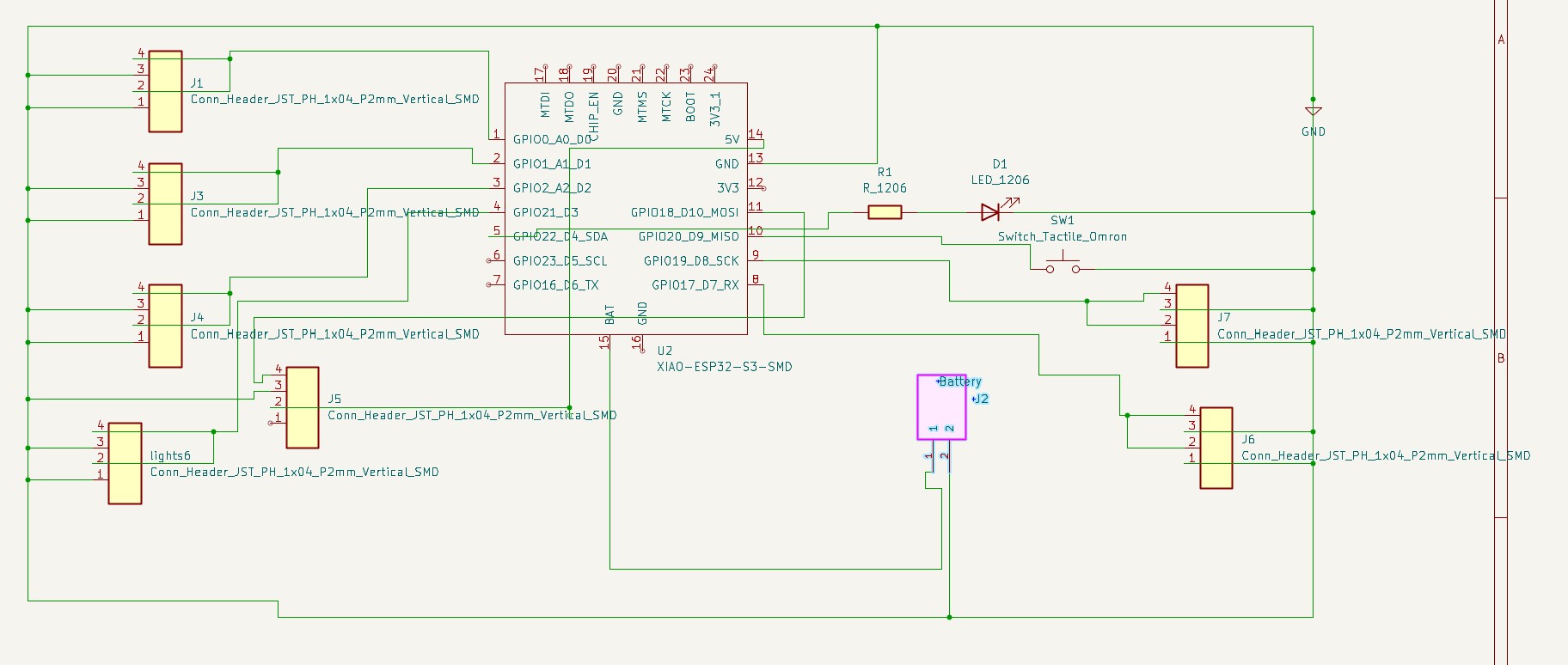
Updated PCB Schematic finished during Week13
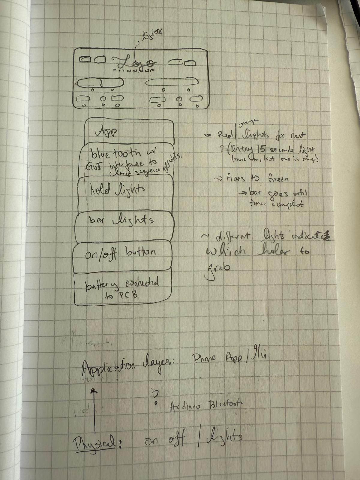
Some big updates include the addition of neopixels and show in the updated design sketch below, surface mounted box headers to include low powered LEDs for all 12 holds, and a button to start
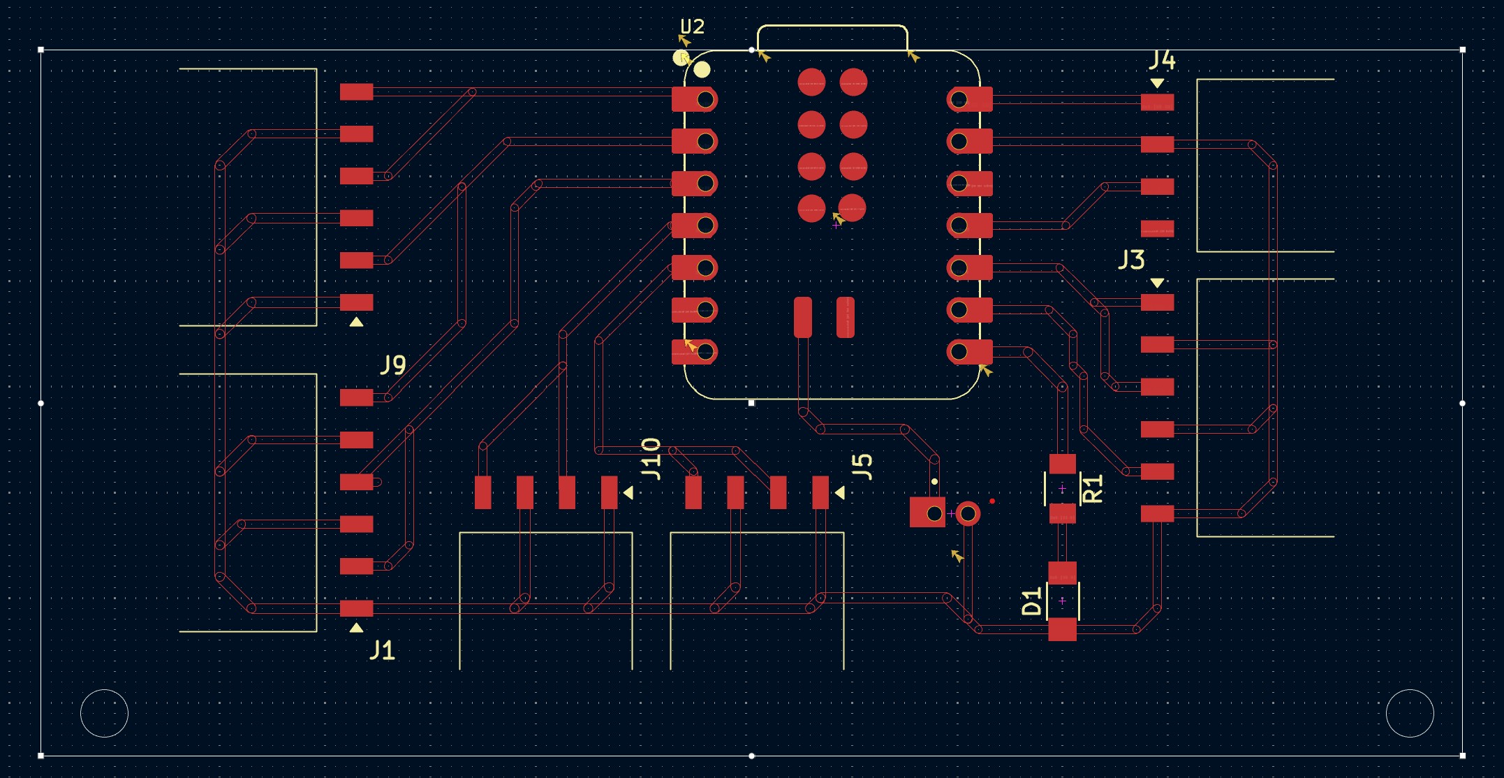
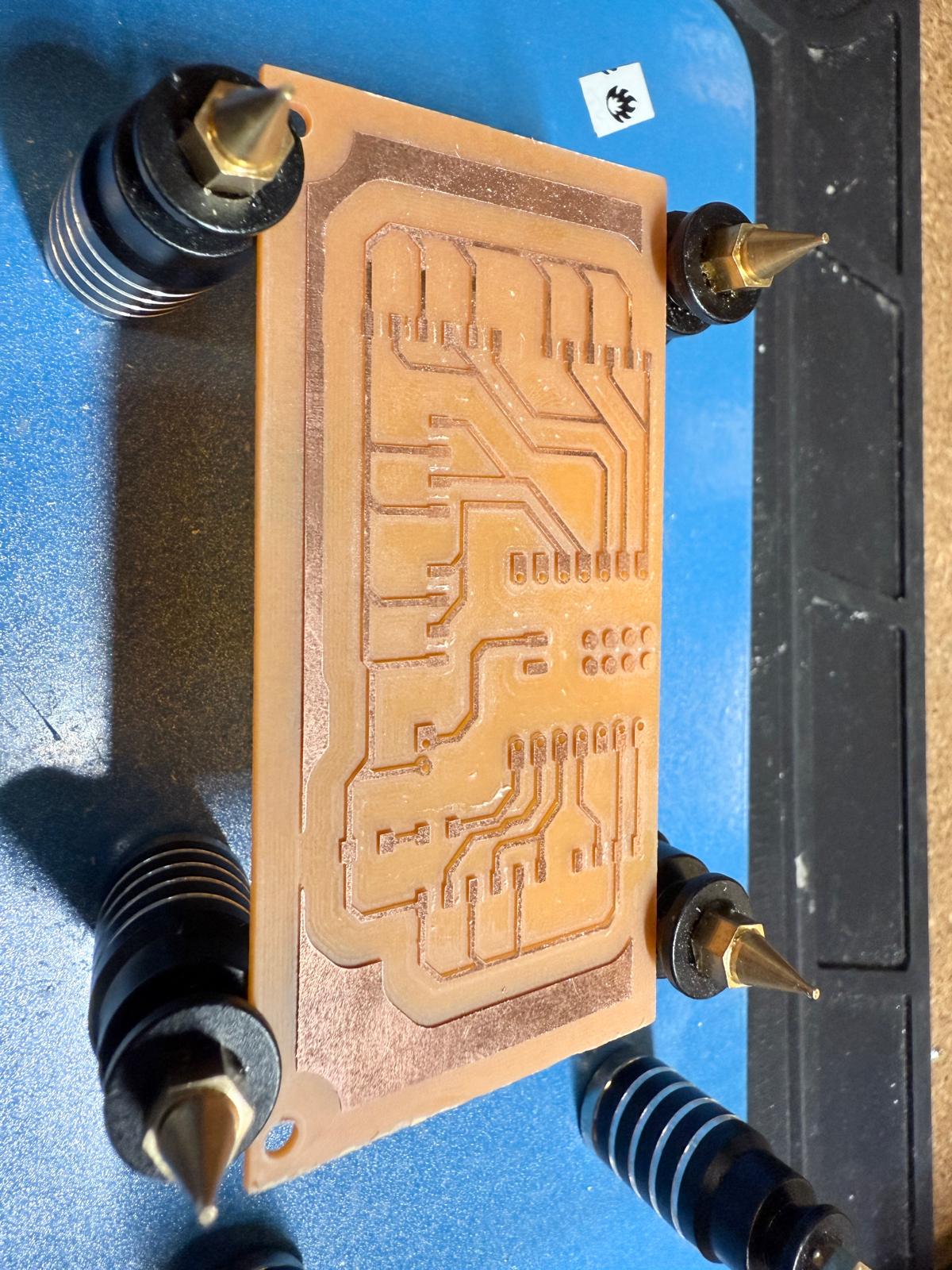
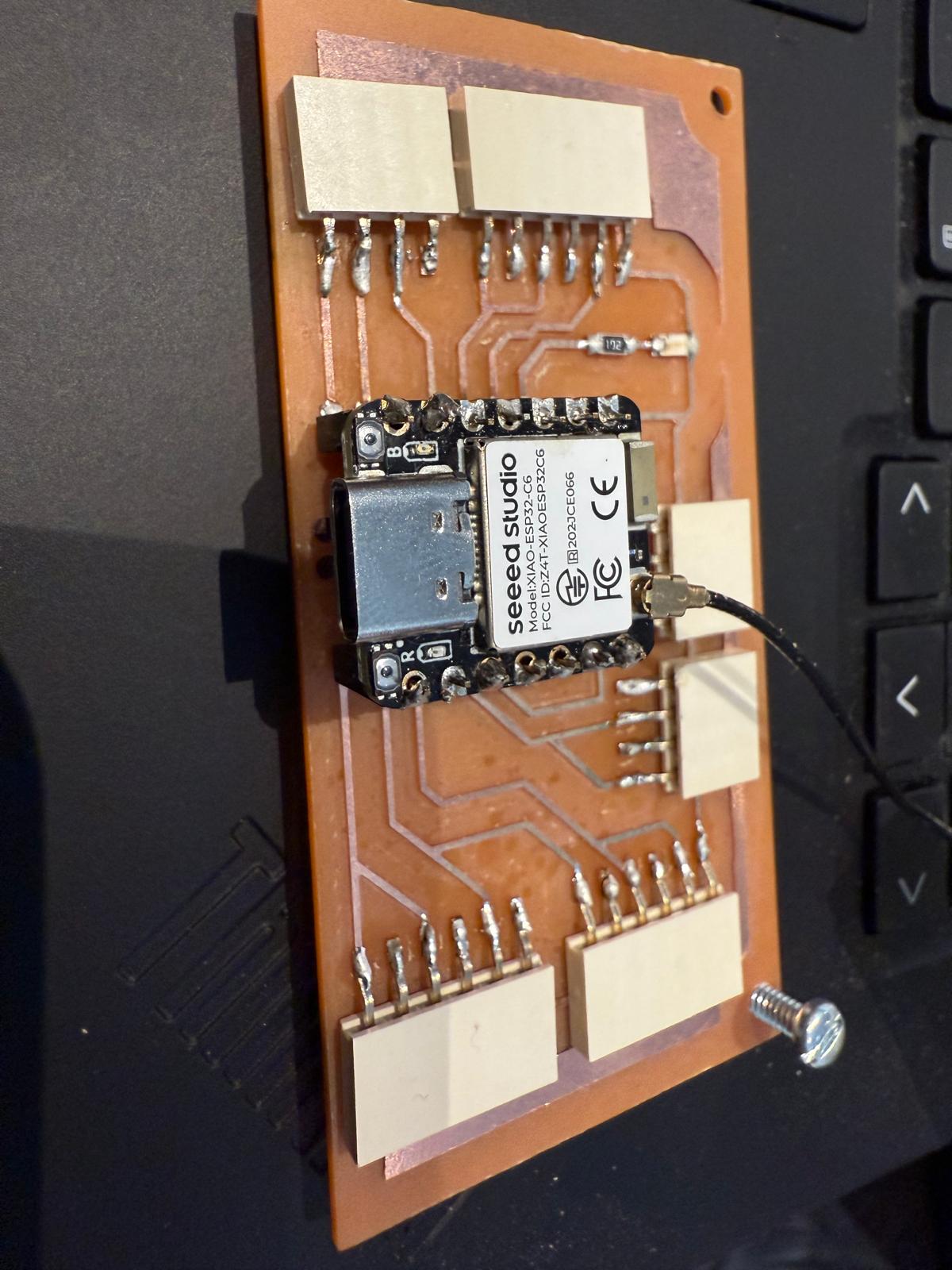
Final PCB Schematic and Layout
Board Milled and Stuffed
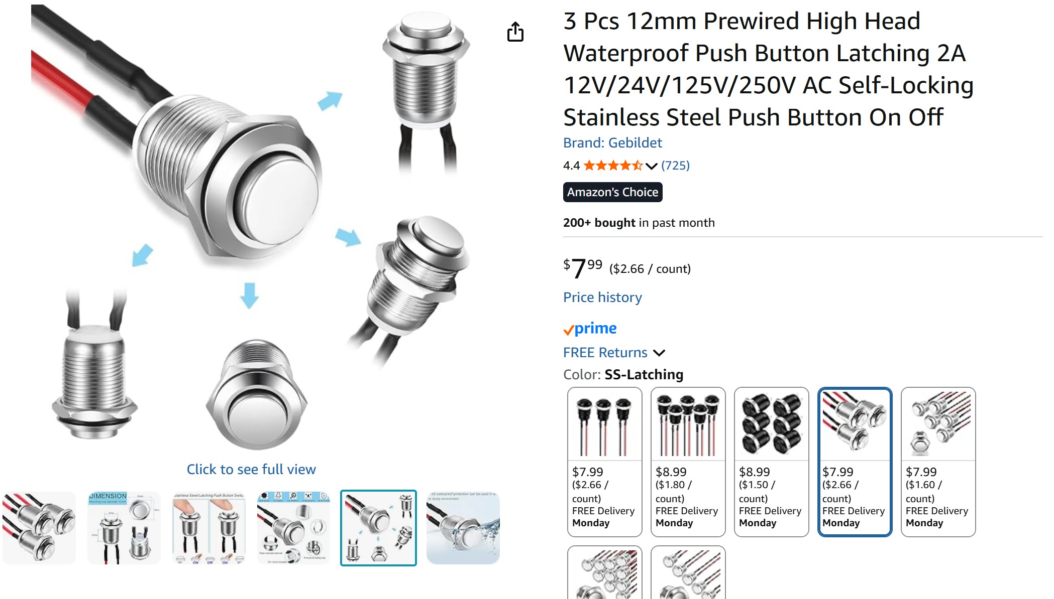
To ensure the button was strain relieved, I bought a large button off amazon. I also bought the RGB LEDS off Amazon.
Testing All Electronics
I tested the Board with all the components plugged in.
Consolidated Design Goals -- MidTerm Review
After pondering the different trigger mechanisms and working on the actuator during machine week, I think a simpler and more elegant solution might be to use a start/stop/pause button with colored LEDs embedded into the logo on the front of the board. The user would still have the option to change the time scale on the design. Overall, it would be easier for spiral development.
Current Design Concept:
Current Design Concept:
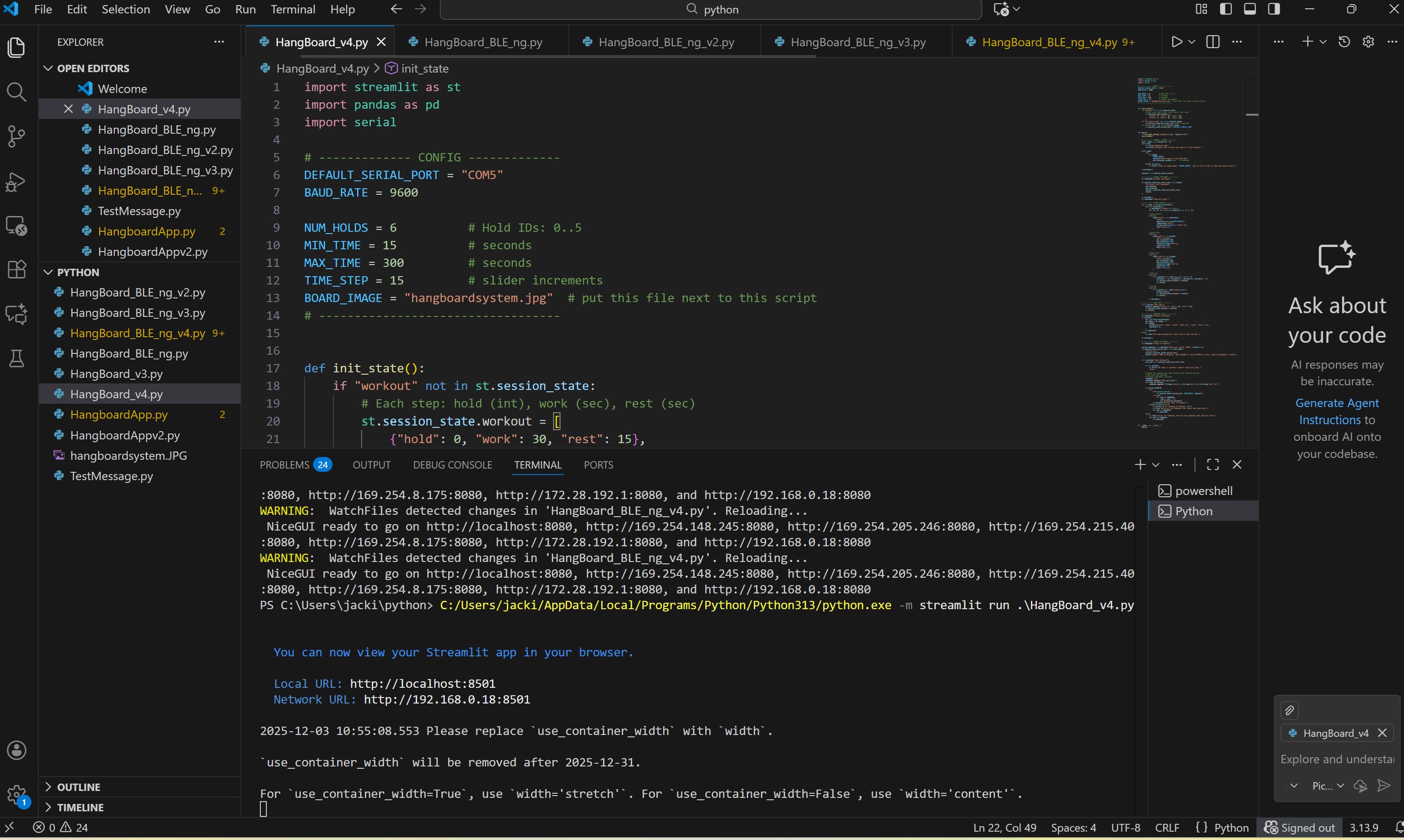
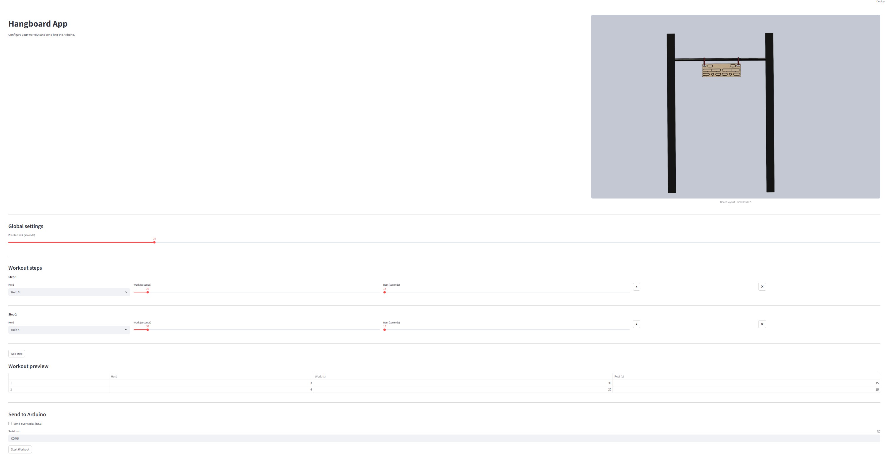
Interface and Application Programming
See week13 here for in-depth overview of integrating Streamlit and Ardinuo to create an interface with all sources listed.
Systems Integration
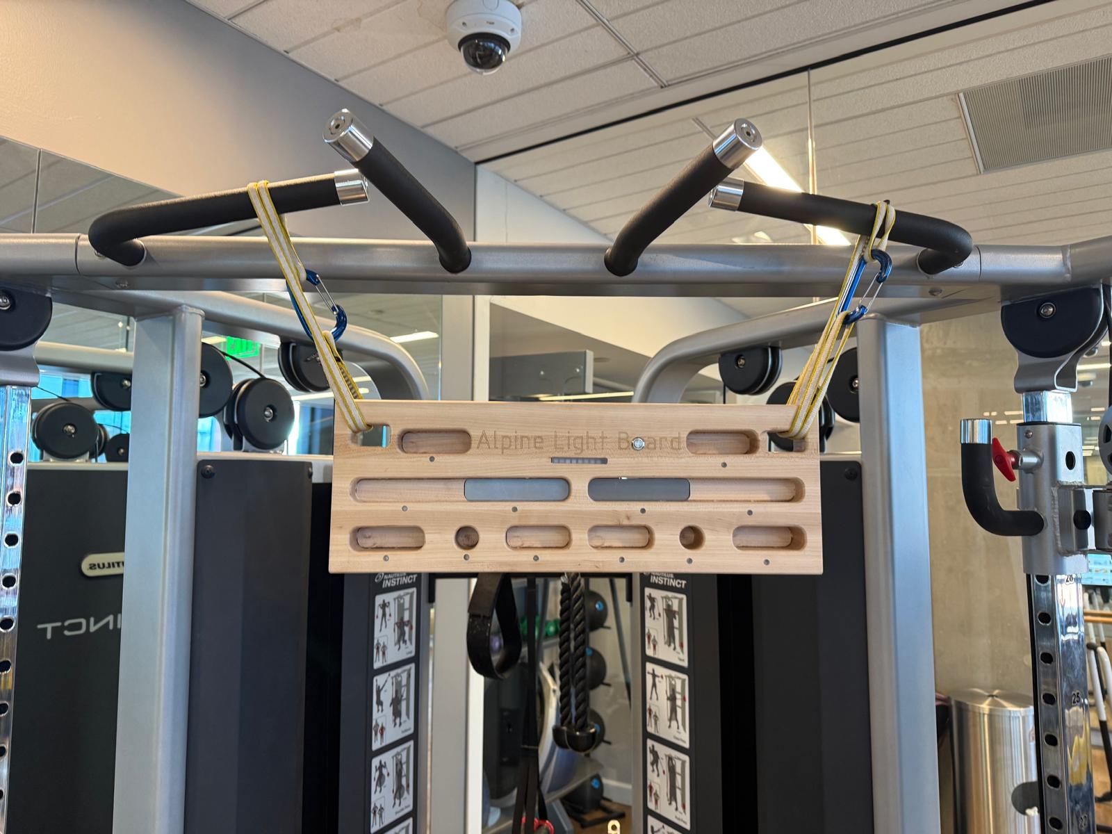
I placed the LEDs and neopixels in the slots in the back of the board, metal laser cut a back-plate from Aluminum
Board Complete!!!!!
Functions Check
Future Work
Create an BLE Companion App, that stores workouts etc., and incorporate an AI chat agent to help create workout
Add a buzzard speaker to indicate when the time starts/stops
Potentially incorporate a pressure sensor or load mechanism that measures a users actual work/rest time