.png)
Group Assignment
- Probe an input device's analog levels and digital signals
Individual Assignment
- measure something: add a sensor to a microcontroller board that you have designed and read it
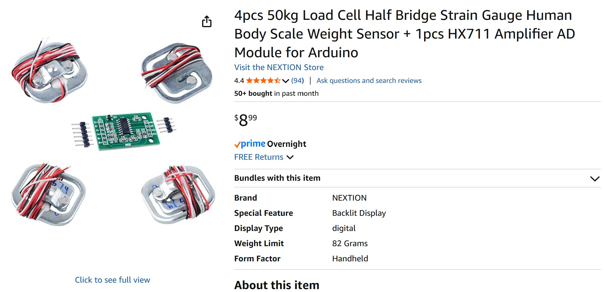
The goal for this week was to work on the input devices for my final project: 1. Button with LED 2. Battery 3. Load sensor
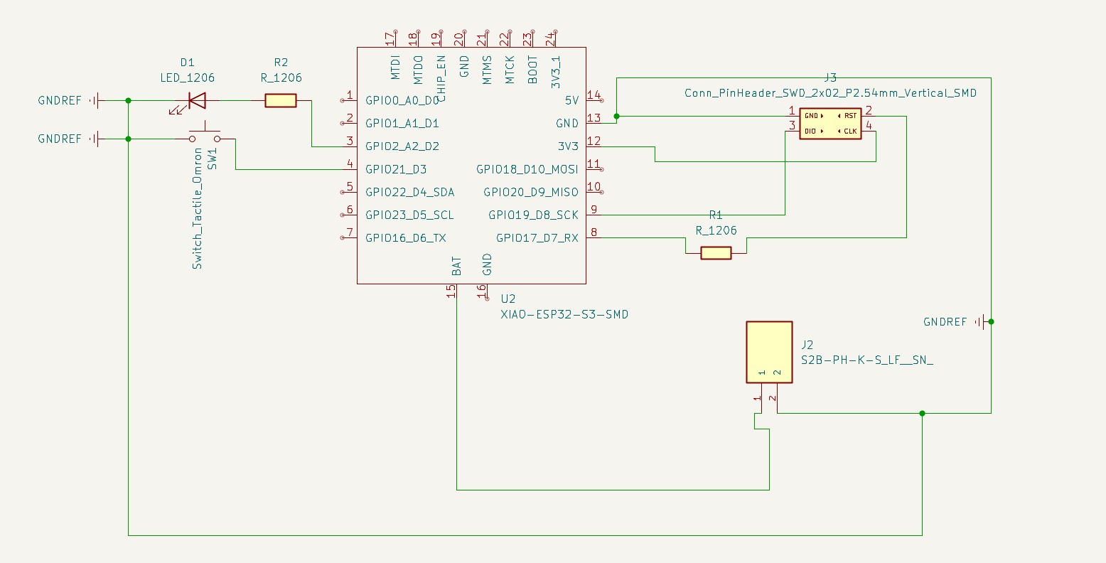
I started with a schematic in KiCad, then attended office hours and asked Anthony some questions about how to connect my Load Sensor to the HX711 amplifier board and about the battery.
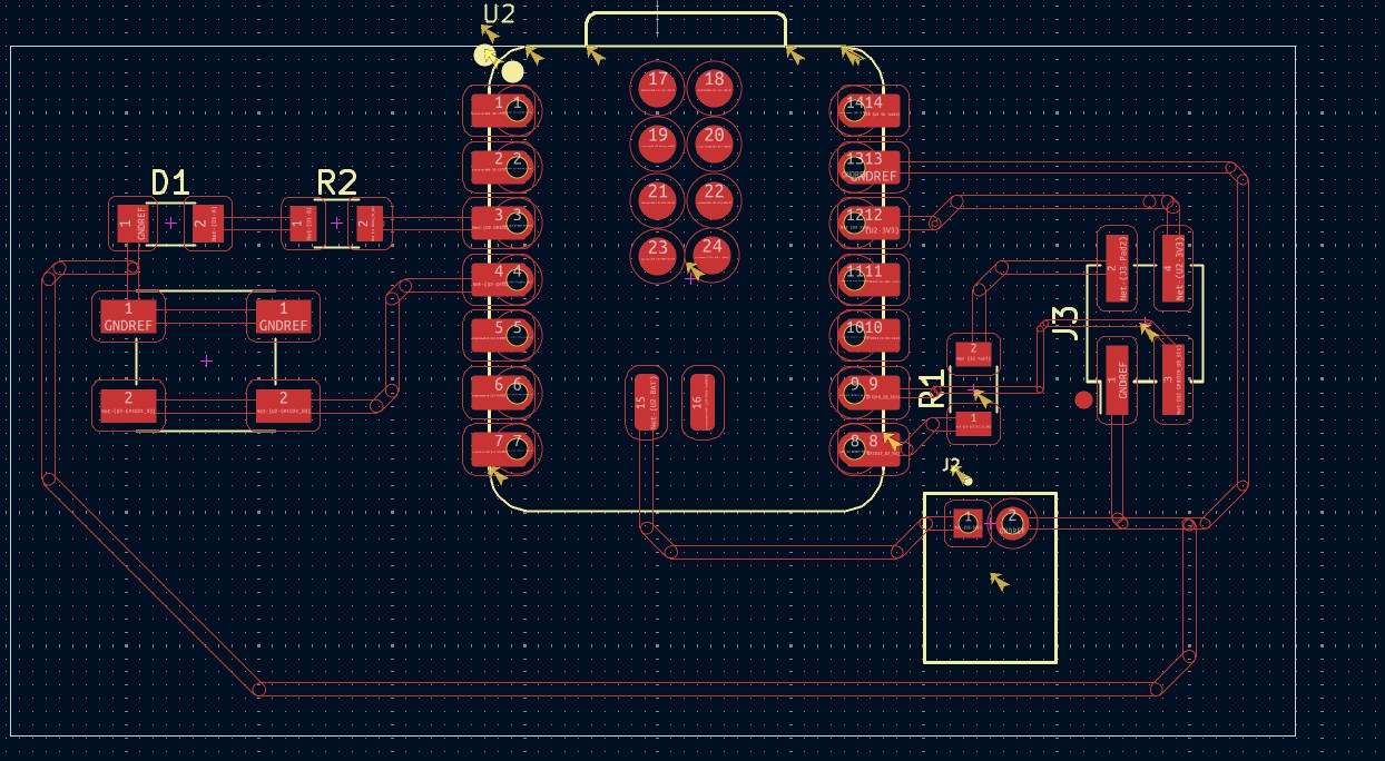
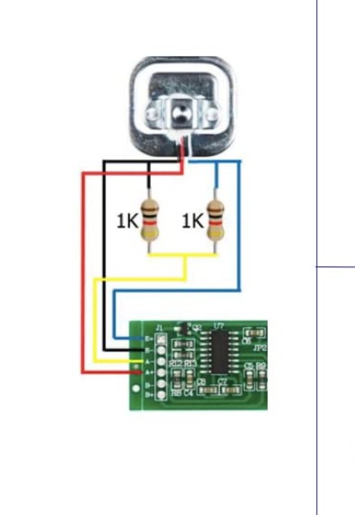
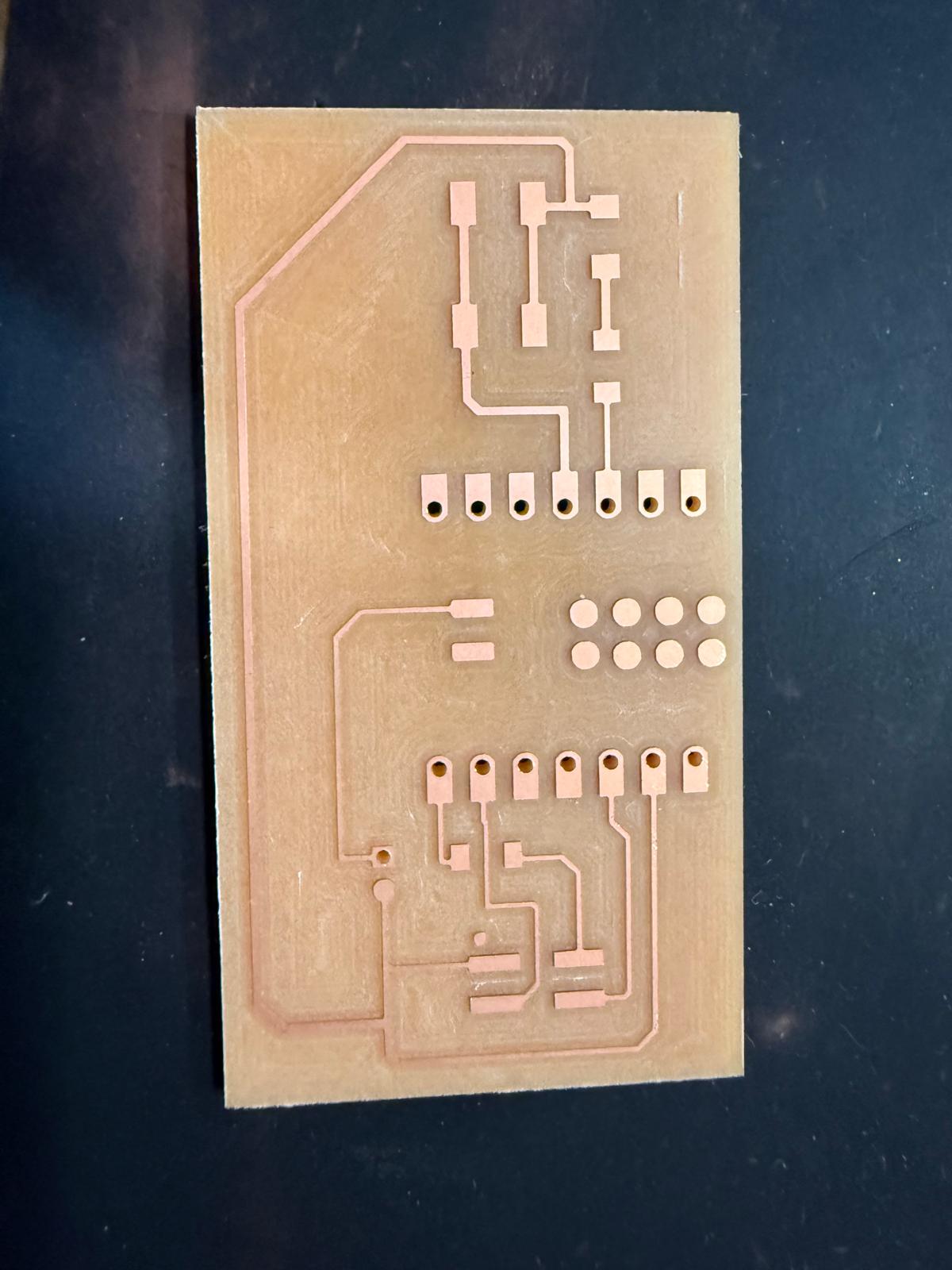
It required some finesse to fit all the traces in KiCad without violating any design rules. I milled and sanded the board and was ready to start assembling everything. The load cell wiring was frustrating to work with and took much longer than expected (but that’s generally the theme of the course).

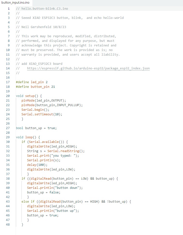
I ran the blink example code (In Arduino IDE -> FILE -> EXAMPLES -> .01 BASICS -> BLINK) to blink the onboard LED on the XIAO ESP32C6 and confirm that the microcontroller was working properly in the Arduino IDE. Next, I updated the code from the class site with a button and an LED. Much to my surprise, nothing worked, so I tried the LED and still nothing.
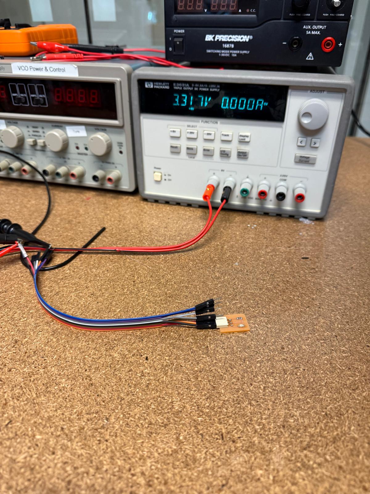
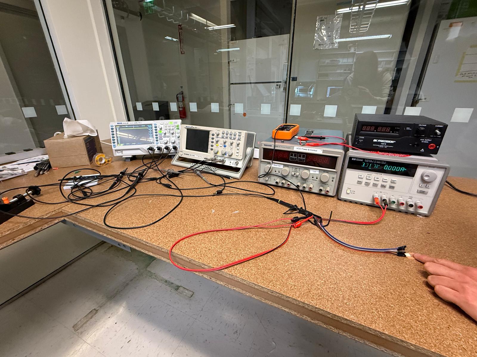
I couldn’t figure out what was going on, I thought maybe I selected the wrong pin and tried all of them. I spent a few hours completely confused and perplexed. I checked all the connections via the multi-meter and was still stuck. Tyler helped me debug and suggested that I use the Multi-meter to test the voltage on the pins that I set to high and helped me use the power input to test the circuit.
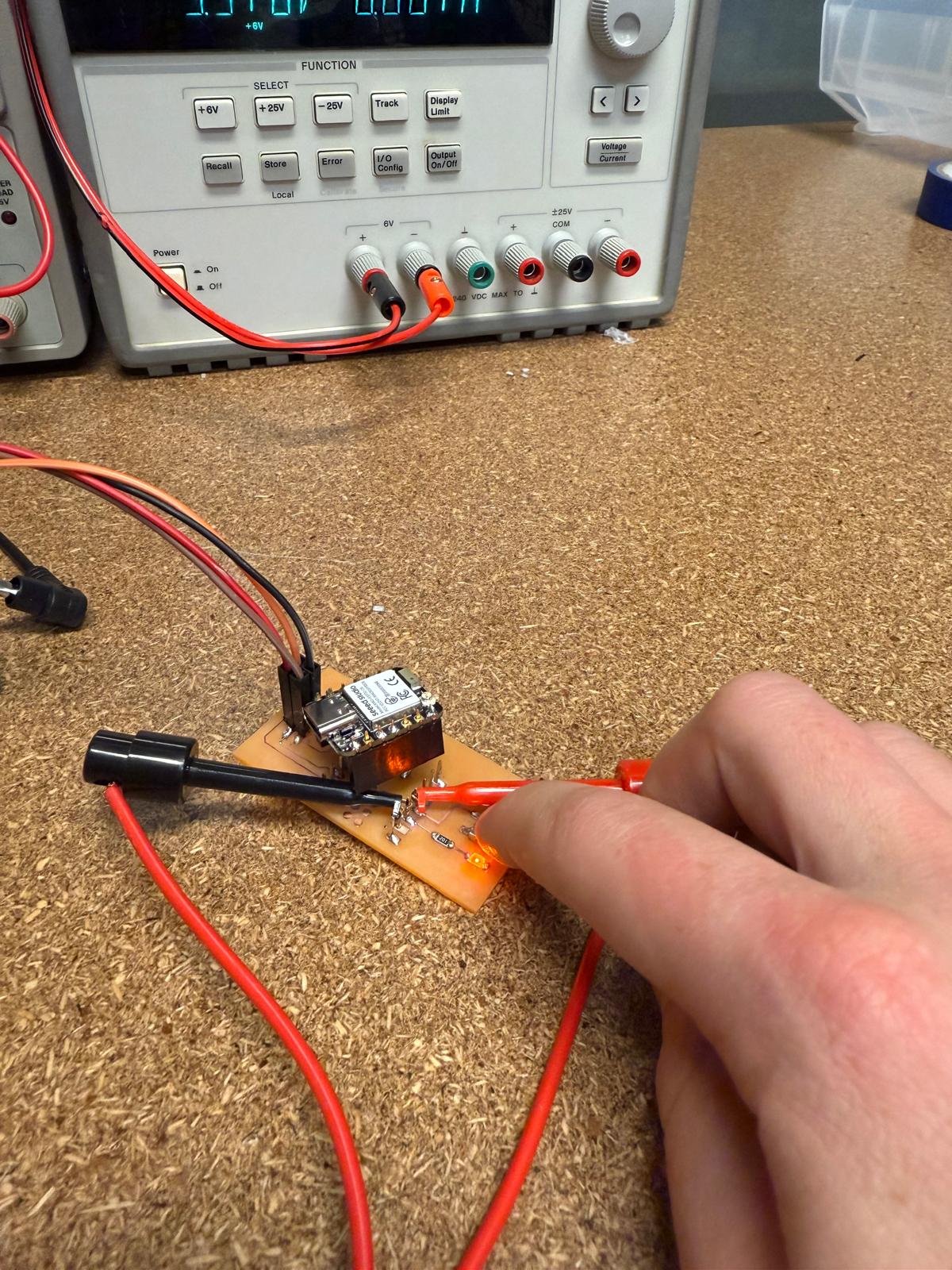
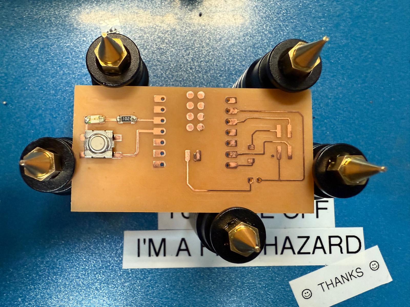
That worked, but I still didn't know why the LED wasn't working. I asked Kristof for help, and he told me that the diode and button weren't connected to ground. In my original schematic they were connected to the ground but I removed all the excess copper to make solder easier
One of the holes wasn't milled, so I went into KiCad increased the diameter of the hole and printed it again. It originally worked on iteration 1, so I was a bit confused.
Ceci was kind enough to press the button while I recorded the video!
I was very excited that the battery worked! I selected an XIAO ESP32C6 as the microcontroller, because it recharges the battery when connected to usb power. When removing the battery, I pulled too hard and ripped off the traces. In the future I will add a switch to make turning the battery on/off easier
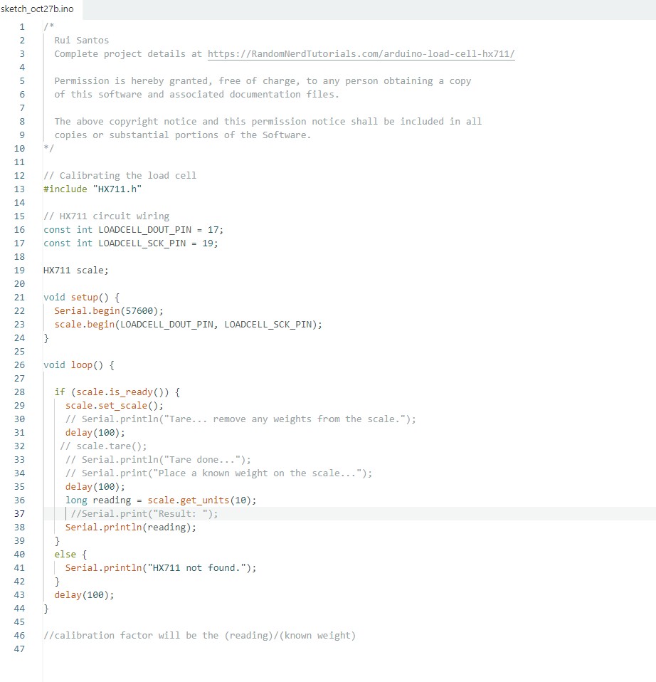
This was a lot simpler than I expected. I read through Random Nerd Tutorial website to get a better understanding of how to use it. I u