Electronics Design
Week 4
This week is designing a circuit board. I have seen my colleges design boards in Eagle, and even as an electronics enthusiast myself, I haven’t designed a board before or to be honest understand how to even design a circuit beyond connecting an dev board to sensors and servos. So this week is going to be very useful and fun.
For the group assignment, I did not contribute to it, but the EECS section is here: https://fab.cba.mit.edu/classes/MAS.863/EECS/Week5.html, I have experience with most of these tools from the past.
The project I am thinking about is having a board that runs a simulation of life. I think the idea that a small world lives in my designed board is quite fascinating. Before I embark on this, I wanted to understand electronics a bit better, I found this SparkFun page to be quite useful to understanding Volts, Current, Resistance. I also chatted with ChatGPT to understand this in more detail: https://chatgpt.com/share/68e16ce4-2e38-8007-b23d-4cece82d63b2. This is my recap: Voltage is the amount of energy each electron has, Current is the amount of electrons moving past a certain point per second. Now Resistance can relate both of them because for electrons to move through some medium at a certain rate (current) they would need some amount of energy to move through it, so that explains the side. Then for , if I have electrons each with some energy and I know how much resistance they face in a medium, then I can figure out their rate of movement (current). I wanted to also understand what is Resistance exactly as well - I learned that is how hard the path of flow is for the electrons. More resistance means the electrons will collide more and in those collisions their net drift towards current movement direction drops and they loose some energy per collision. This is why it affects both and . Now that I have a vague understand of electricity, I started to think about board design.
I need a LED matrix, and I searched for some previous builds: https://hackaday.io/project/192348-diy-customized-8x8-led-matrix-tutorial, https://srituhobby.com/how-to-make-an-8x8-led-matrix-display-using-an-arduino-nano/?srsltid=AfmBOoq5-nMJWaKau80hzs2HfYsGuFe71O8NJ48bGBgb2O7JRkPjVqUl#google_vignette
Ok so this will require a microcontroller and an LED matrix. I know from prior experience we can use multi-plexing to control the LED Matrix.
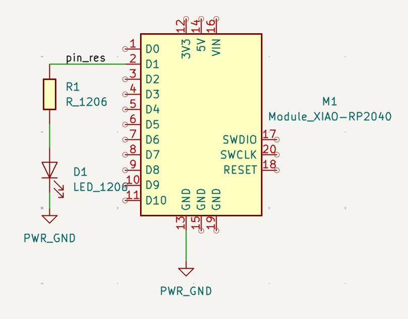
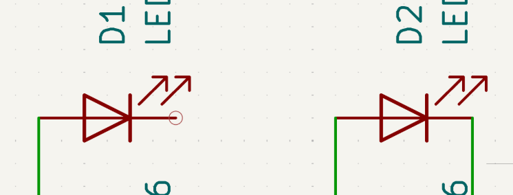
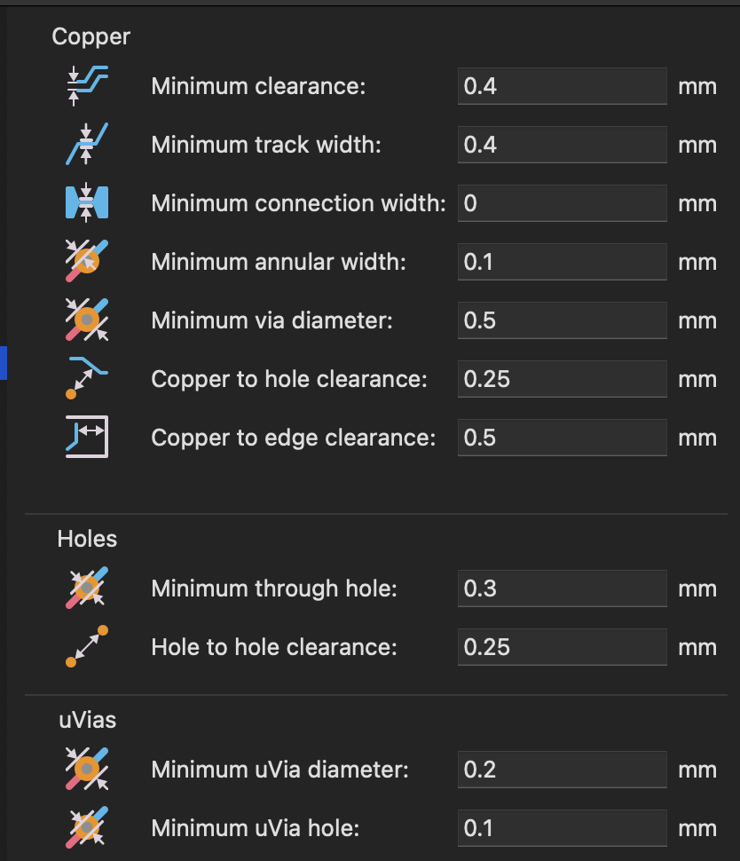
The first step I did was learn the basics of KiCad from the recitation video. I ended up replicating the board with an LED. I set the design rules of 0.4 mm minimum clearance and track width.
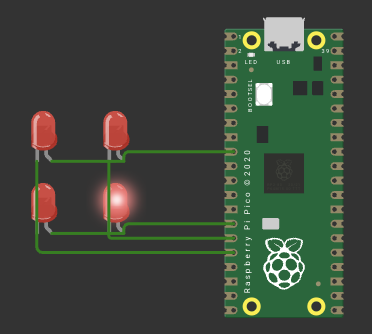
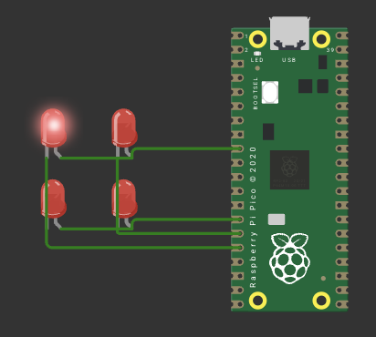
Then I decided to design the circuit in Wokwi after Saleem answer my question of once you have a KiCad design how do you simulate it. Therefore, before I design my board in KiCad, I wanted to make sure it works in the simulation, and the LEDs matrix is working properly. I decided to use the Raspberry Pico board.
For this assignment I am going to start small with a 2x2 led matrix. This follows something I want to be better at : spiral development.
First I checked if I can control a single led.
void setup() {
  pinMode(6, OUTPUT);
  pinMode(10, OUTPUT);
  pinMode(11, OUTPUT);
  pinMode(12, OUTPUT);

  digitalWrite(6, LOW);
  digitalWrite(10, LOW);
  digitalWrite(11, LOW);
  digitalWrite(12, LOW);
}

void loop() {
  digitalWrite(6, LOW);
  digitalWrite(10, HIGH);
  digitalWrite(11, LOW);
  digitalWrite(12, HIGH);
}
  digitalWrite(6, HIGH);
  digitalWrite(10, LOW);
  digitalWrite(11, HIGH);
  digitalWrite(12, LOW);
This works!
Now time to design the board in KiCad.
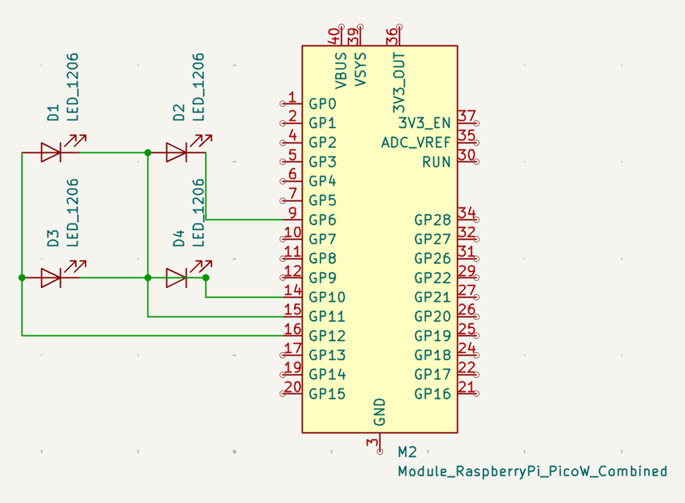
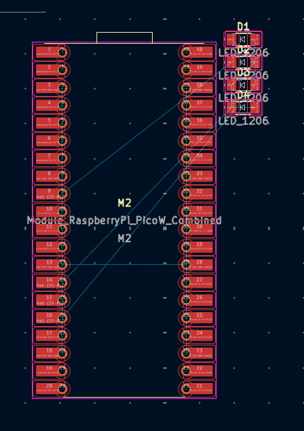
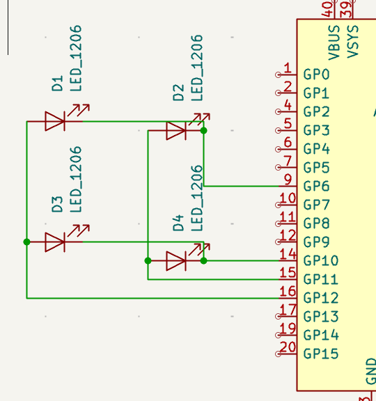
Initially the board came with all the LEDs next to eachother. I needed to separate them and wire them. But, as shown below after spreading them out something was clearly not right, LED D4 has a missing connection.
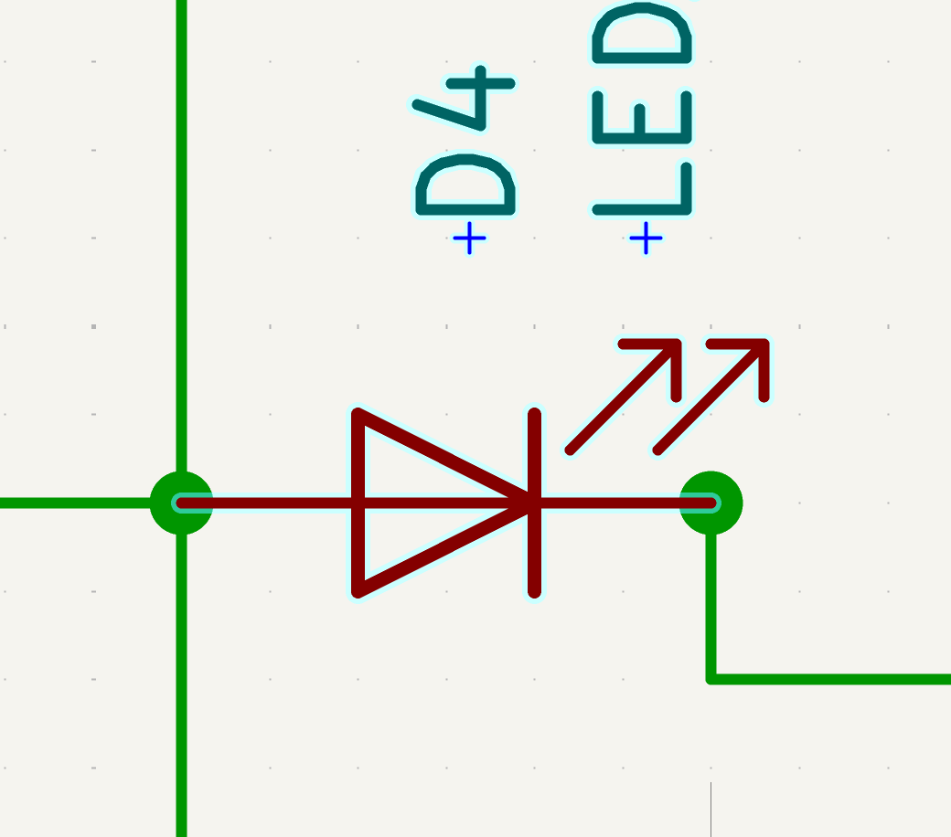
The strange part is on the schematic, D4 seems to be connected. It actually ended up being I just needed to move D4 on the PCB and the connection showed up.
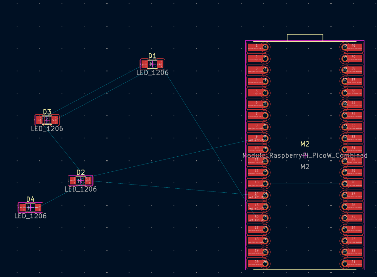
As I was trying to route all the wires I quickly got trapped. (Thank god I didn’t do an 8x8 which was my initial plan). Then I realized another problem my original schematic was wrong; I was unable to wire through the LED.
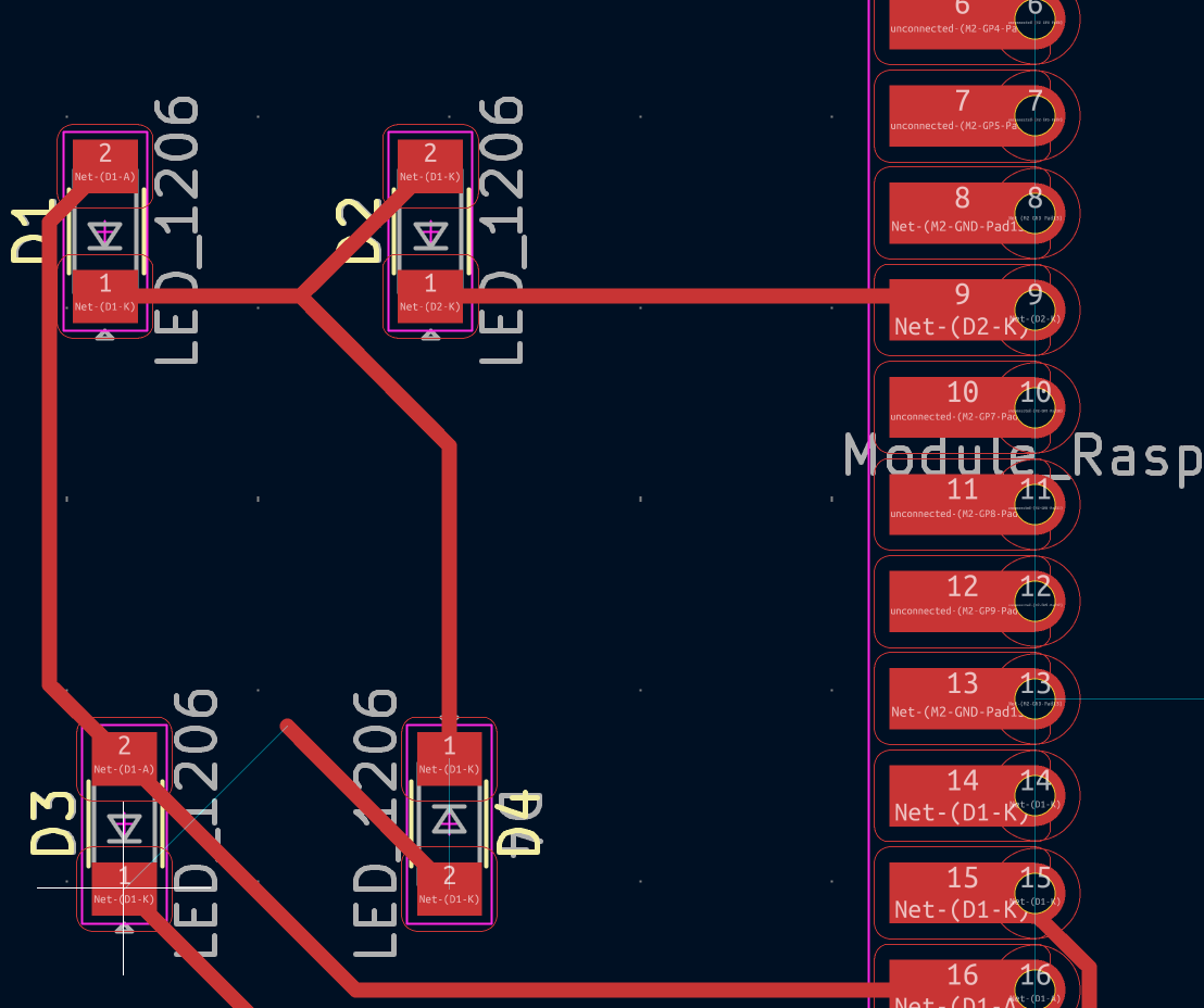
To fix this I shifted the LEDs.
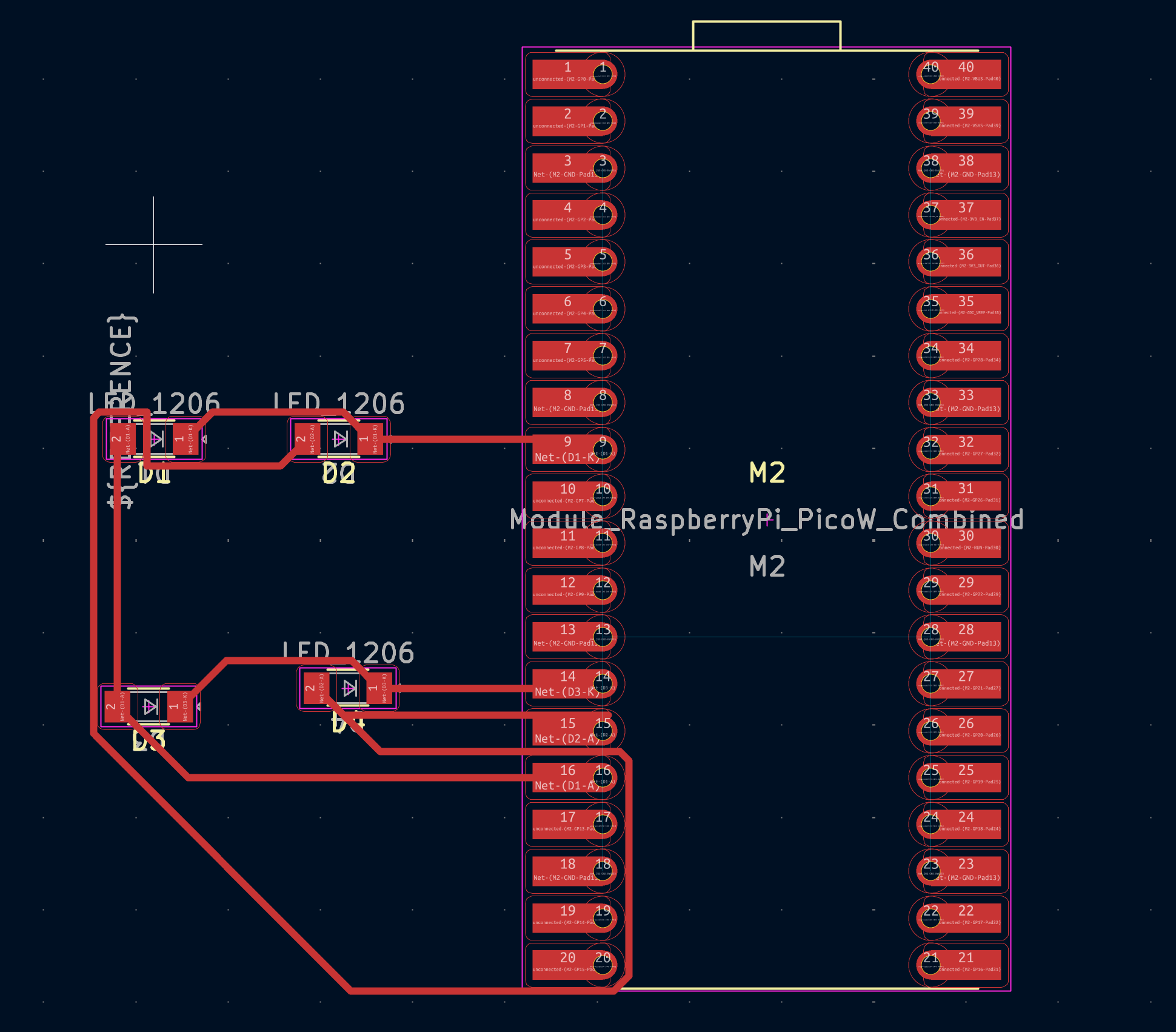
I had to spend some time figuring out how to route all the wires, but finally I was able to use the space between the LEDs to make it all work. I think this passes the design clearance because I set the minimum track width and clearance of 0.4 mm.
Here are the files for the KiCad.
https://wokwi.com/projects/443936296216305665
This is the Wokwi simulation.