Week 5 - Group Assignment Summary
PCB Production Process Characterization & Board House Submission
Assignment Overview
This page summarizes the group assignment for Week 6, focusing on characterizing the design rules for in-house PCB production processes and submitting a PCB design to a board house. This comprehensive assignment covers both local fabrication capabilities and professional manufacturing workflows.
Week 5 Group Assignment Summary
A comprehensive summary of the Week 5 group assignment focusing on PCB production process characterization and board house submission. This assignment provided essential hands-on experience with both in-house fabrication and professional manufacturing workflows.
Assignment Overview
The Week 5 group assignment consisted of two main components: characterizing design rules for in-house PCB production processes and submitting a PCB design to a board house for professional manufacturing.
Key Components
- Design Rule Characterization: Comprehensive testing of in-house PCB production capabilities through systematic evaluation of trace widths, spacing tolerances, and mechanical durability
- Board House Submission: Evaluation of professional PCB manufacturing services through JLCPCB submission to compare design rules, pricing, and production capabilities
Design Rule Characterization Results
Systematic testing revealed the practical limitations and capabilities of in-house PCB fabrication processes.
🔧 Characterized Design Rules
Durability Testing Results
Mechanical stress testing provided insights into the practical limitations of in-house PCB production.
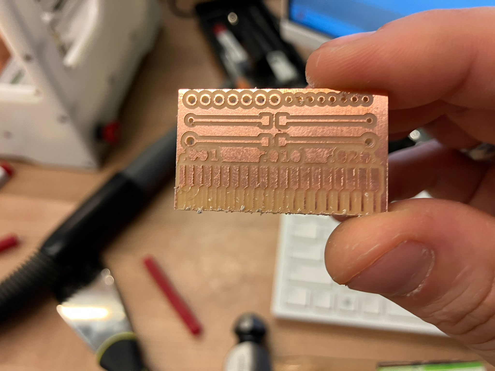
Pre-test: Initial trace pattern before mechanical stress
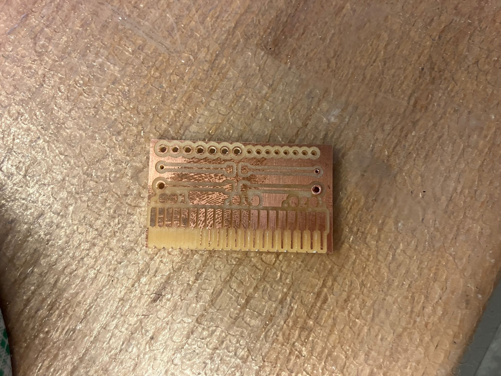
Post-test: Surviving traces after mechanical stress
PCB Milling Process
The in-house PCB fabrication process using the Othermill machine for precise trace milling and hole drilling.
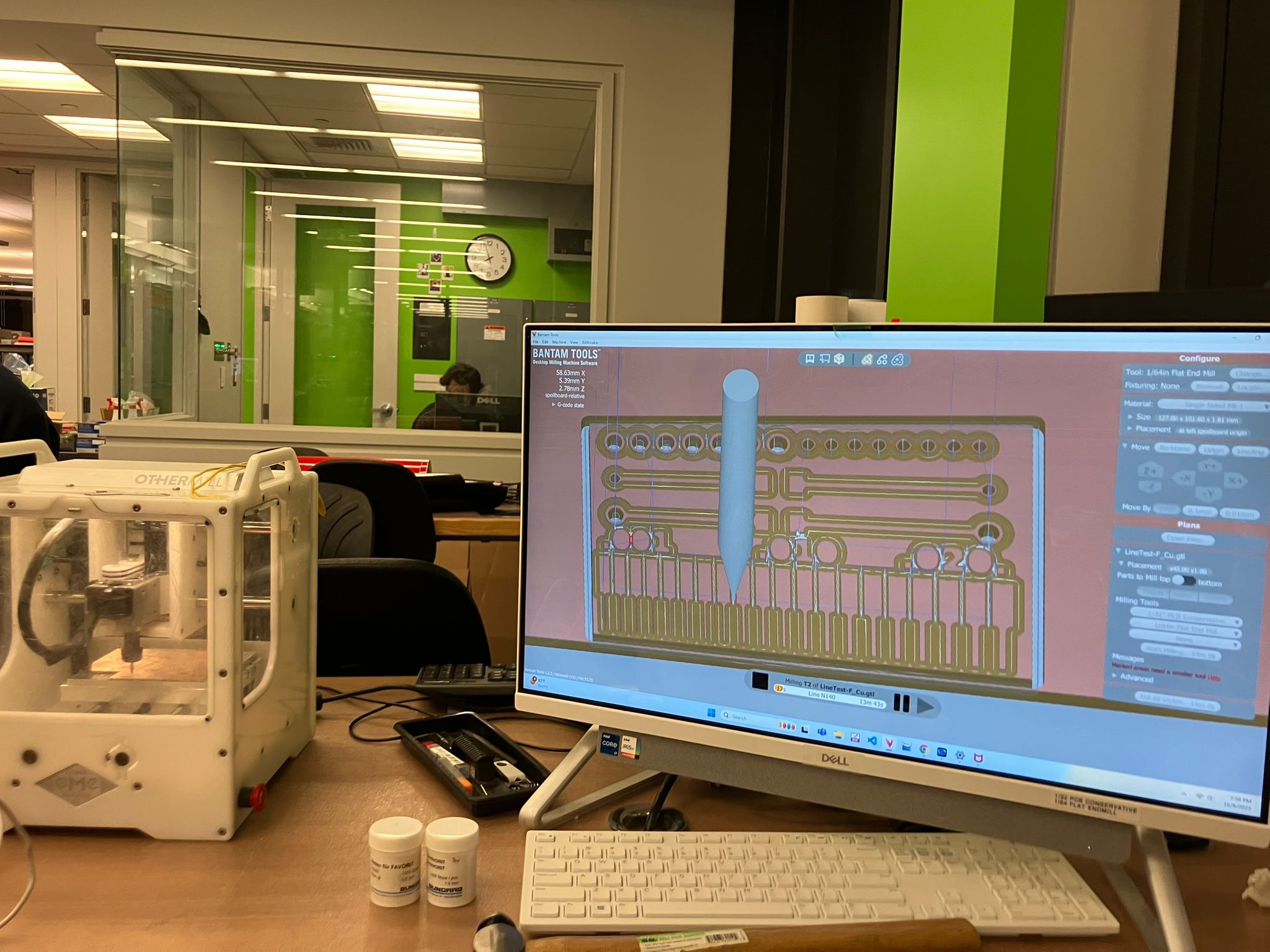
PCB milling process using the Othermill machine
Board House Submission
Professional PCB manufacturing submission workflow through JLCPCB, including design file preparation and production specifications.
JLCPCB Submission Workflow
- Access JLCPCB online platform and create account
- Upload PCB design files (Gerber format)
- Select aluminum substrate (preferred over FR4 for machining compatibility)
- Configure production parameters and place order
Additional Process Images
Documentation of the complete PCB production workflow from milling to final assembly.
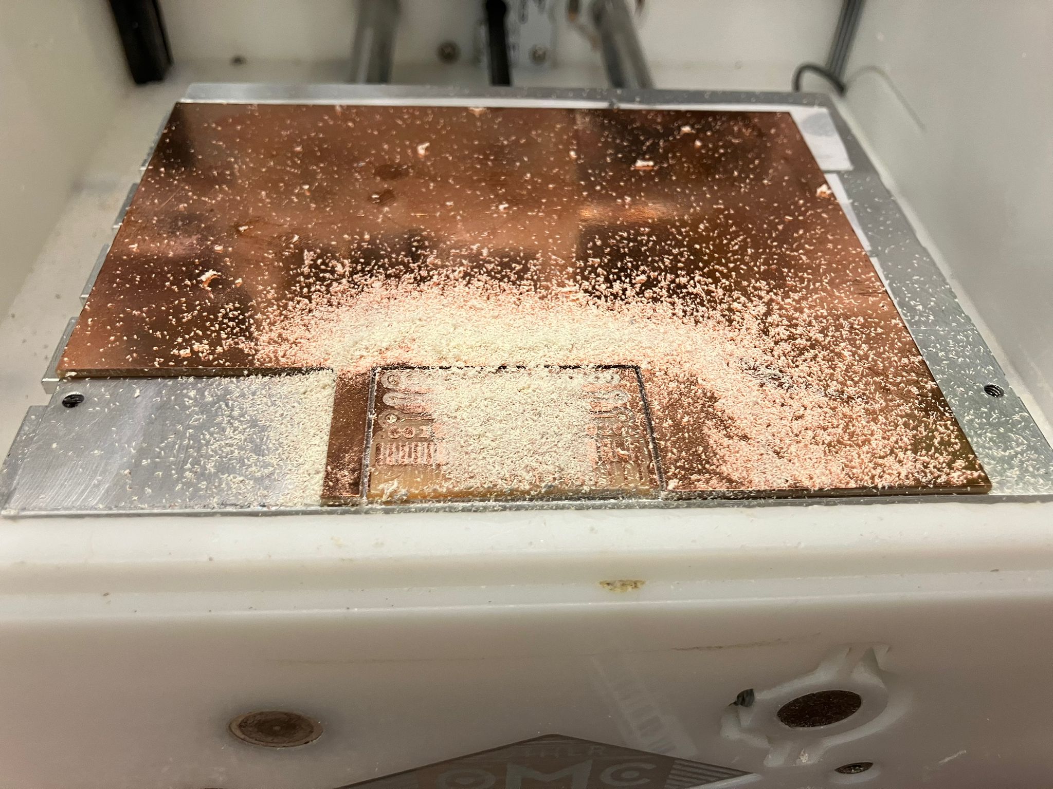
PCB surface preparation
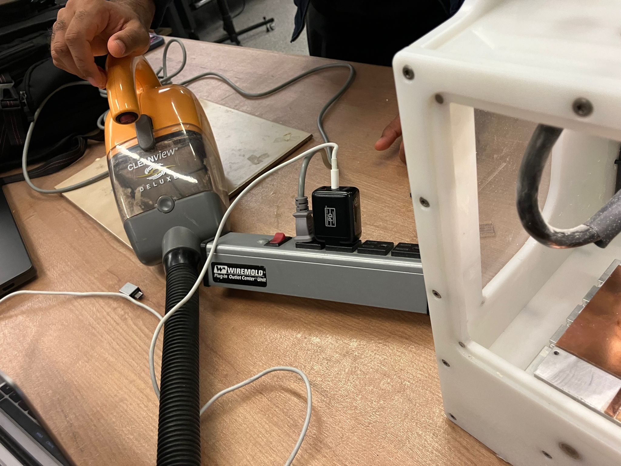
CleanView Deluxe vacuum system for debris removal
Full Assignment Details
For complete details on the Week 5 group assignment, including comprehensive design rule characterization, board house submission process, and detailed results, please visit the full assignment page.
🔗 View Full Week 5 Group Assignment DetailsGroup Assignment: PCB Production Process
Characterize the design rules for your in-house PCB production process and submit a PCB design to a board house.
Assignment Components
This assignment consists of two main components that provide comprehensive understanding of PCB manufacturing at different scales and quality levels.
In-House Process
Characterize design rules for local PCB production capabilities
Board House Submission
Submit PCB design to professional manufacturing service
In-House PCB Production Design Rules
Characterization of design rules and limitations for local PCB fabrication processes, including trace width, spacing, via sizes, and manufacturing constraints.
🔧 Trace Design Rules
Limited by milling bit diameter and precision
Higher current carrying capacity required
Balances space efficiency with manufacturability
Critical for RF and high-speed digital applications
📏 Spacing Requirements
Prevents short circuits and crosstalk
Ensures proper solder joint formation
Prevents solder bridging during assembly
Prevents damage during handling and mounting
🔗 Via Specifications
Limited by drill bit availability and precision
Ensures reliable via formation and plating
Prevents drill bit breakage and manufacturing issues
Maintains electrical isolation and manufacturability
📐 Component Placement
Enables proper soldering and rework access
Ensures reliable solder joint formation
Prevents silkscreen interference with soldering
Limited by smallest available drill bit
⚡ Electrical Constraints
Prevents trace overheating and failure
Ensures electrical safety and reliability
Critical for high-frequency signal integrity
Maintains proper grounding and shielding
🏭 Manufacturing Limitations
Limited by available substrate materials
Limited by local fabrication capabilities
Most cost-effective finish for prototyping
Limited by milling precision and tooling
Board House Submission Process
Professional PCB manufacturing submission workflow, including design file preparation, manufacturer selection, and quality specifications.
Professional Manufacturing Submission
Submit a PCB design to a professional board house for high-quality manufacturing with advanced capabilities and tighter tolerances.
Submission Requirements
- Gerber Files: Complete set of manufacturing files (copper layers, solder mask, silkscreen, drill files)
- Drill File: NC drill file with hole locations and sizes
- Pick and Place File: Component placement coordinates for automated assembly
- Bill of Materials (BOM): Complete component list with part numbers and specifications
- Assembly Drawing: Visual reference for component placement and orientation
Manufacturing Specifications
- Board Dimensions: Specify exact board size and thickness requirements
- Layer Count: Define number of copper layers and stackup
- Surface Finish: Choose appropriate finish (ENIG, HASL, OSP, etc.)
- Via Specifications: Define via types (through-hole, blind, buried)
- Impedance Control: Specify controlled impedance requirements
Quality Standards
- IPC Standards: Follow IPC-6012 for PCB quality requirements
- Electrical Testing: Specify electrical test requirements (flying probe, bed of nails)
- Visual Inspection: Define visual inspection criteria and standards
- Packaging: Specify packaging requirements for shipping and handling
Design Rule Comparison
Comparison between in-house and professional manufacturing capabilities to understand the trade-offs and limitations of each approach.
🏠 In-House Manufacturing
🏭 Professional Manufacturing
Design Optimization Strategies
Strategies for optimizing PCB designs to work effectively with both in-house and professional manufacturing processes.
Design for Manufacturing (DFM) Principles
- Conservative Design Rules: Use larger features when possible to improve manufacturability
- Standard Components: Choose components with standard footprints and availability
- Test Points: Include test points for debugging and verification
- Fiducial Marks: Add fiducial marks for automated assembly alignment
- Panelization: Consider panelization for efficient manufacturing and assembly
Quality Control and Testing
Quality control procedures and testing methodologies for both in-house and professionally manufactured PCBs.
🔍 In-House Testing
✅ Professional Testing
Special Thanks to Our Section
We would like to express our sincere gratitude to all members of our section for their invaluable collaboration throughout this group assignment. Your contributions were essential to the success of this comprehensive PCB production process characterization project.
Collaboration Activities
- Design rule documentation and measurement
- Manufacturing process analysis and characterization
- Board house research and selection
- Quality control procedure development
Knowledge Sharing
- PCB design best practices and guidelines
- Manufacturing process limitations and capabilities
- Quality control methodologies and testing
- Professional manufacturing workflows
This collaborative effort demonstrates the power of teamwork in technical education and hands-on learning. The collective knowledge and shared experiences significantly enhanced our understanding of PCB manufacturing processes and design optimization strategies.
References
- PCB Design Guidelines
Industry standards and best practices for PCB layout and manufacturing - Manufacturing Process Documentation
In-house fabrication procedures and equipment specifications - Board House Specifications
Professional manufacturing capabilities and design rule requirements - IPC Standards
IPC-6012 and related standards for PCB quality and manufacturing - Design for Manufacturing (DFM)
Guidelines for optimizing designs for manufacturability and cost
Ethical AI Use
Documentation of AI tool usage for this week's group assignment summary and website development work.
Week 6 - Group Assignment Summary Development
This session covers the development of the Week 6 page for the PCB production process characterization group assignment, including content structure, technical documentation, and comprehensive coverage of PCB manufacturing processes.
AI Development Documentation
Complete development transcript documenting the AI-assisted creation of the Week 6 group assignment page, including content structure, technical documentation, and website development process.
Week 6 - Week 5 Summary Integration
This session covers the integration of Week 5 group assignment summary into the Week 6 page, including content extraction, image integration, and comprehensive documentation of PCB production processes.
AI Development Documentation
Complete development transcript documenting the AI-assisted integration of Week 5 group assignment summary into Week 6, including content extraction, image integration, and comprehensive documentation.
Key AI Activities
- Content Structure
Creation of comprehensive HTML structure for PCB manufacturing documentation - Technical Documentation
Development of detailed sections covering design rules and manufacturing processes - Process Integration
Implementation of in-house and professional manufacturing workflow information - Navigation Integration
Addition of Week 6 link to main index page for seamless course navigation - Week 5 Summary Integration
Extraction and integration of Week 5 group assignment content into Week 6 page - Image Integration
Integration of key images from week6groupassignment folder with proper styling and captions - Link Integration
Addition of external link to full Week 5 assignment details with proper accessibility attributes
AI Tools Used
- Cursor AI
Code generation, content structuring, and website development assistance - Technical Content Generation
Creation of comprehensive PCB manufacturing process documentation - Website Design
Implementation of consistent styling and responsive layout - Content Integration
Seamless integration of Week 5 content into Week 6 page structure - Image Processing
Integration and styling of process images with proper responsive layouts