Output Devices
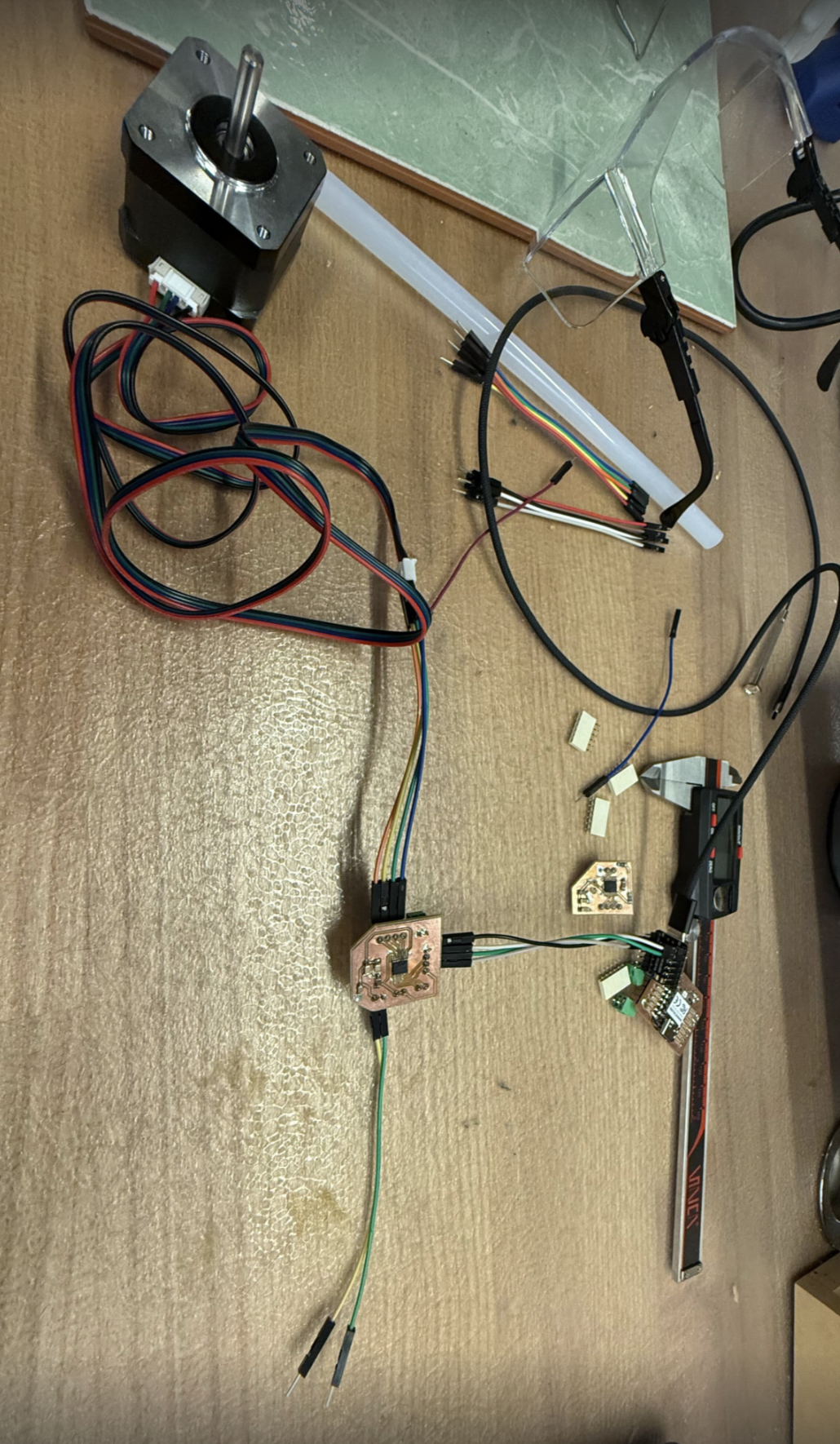
For this week’s assignment I am building towards my final project - which is recreating SpiRobs. I need stepper motors for this, so I decided to build a stepper motor driver. This week was by far the hardest week for me. You will see why soon.
Group Assignment
I didn’t participate in it - but here is our groups link: https://fab.cba.mit.edu/classes/MAS.863/EECS/Week8.html
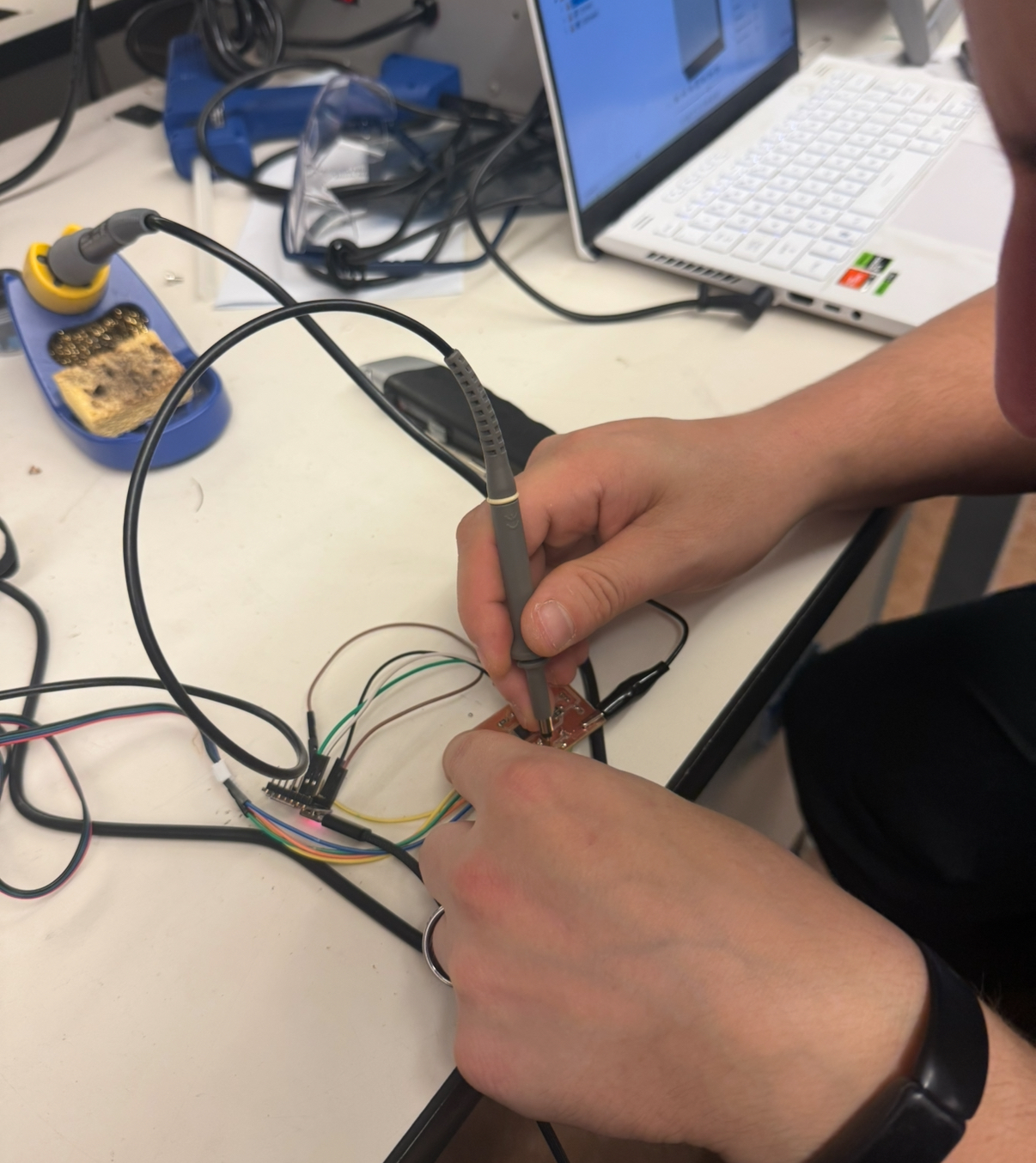
Anthony and I did hook up our stepper motor driver to the oscilloscope to measure the current being drawn and it was 0 - since my board was initially not working.
Acknowledgments
This board would not exist in a functional state if it wasn’t for Anthony. Just do find and type in Anthony and that will speak for itself.
Round 1
I first looked at the parts we have for a stepper driver, and we had https://www.digikey.com/en/products/detail/texas-instruments/DRV8428PWPR/13563046
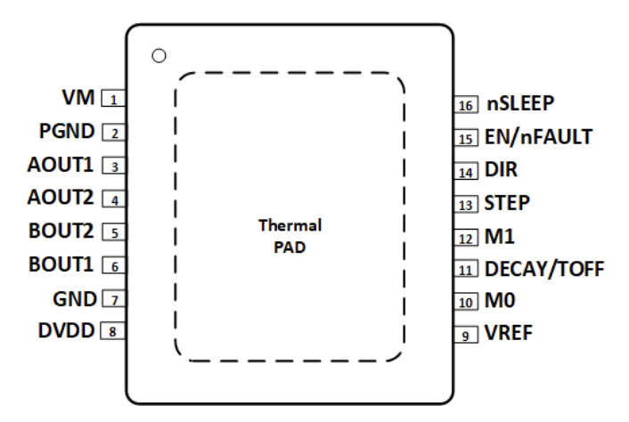
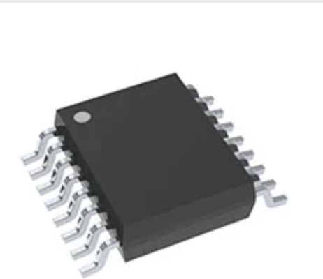
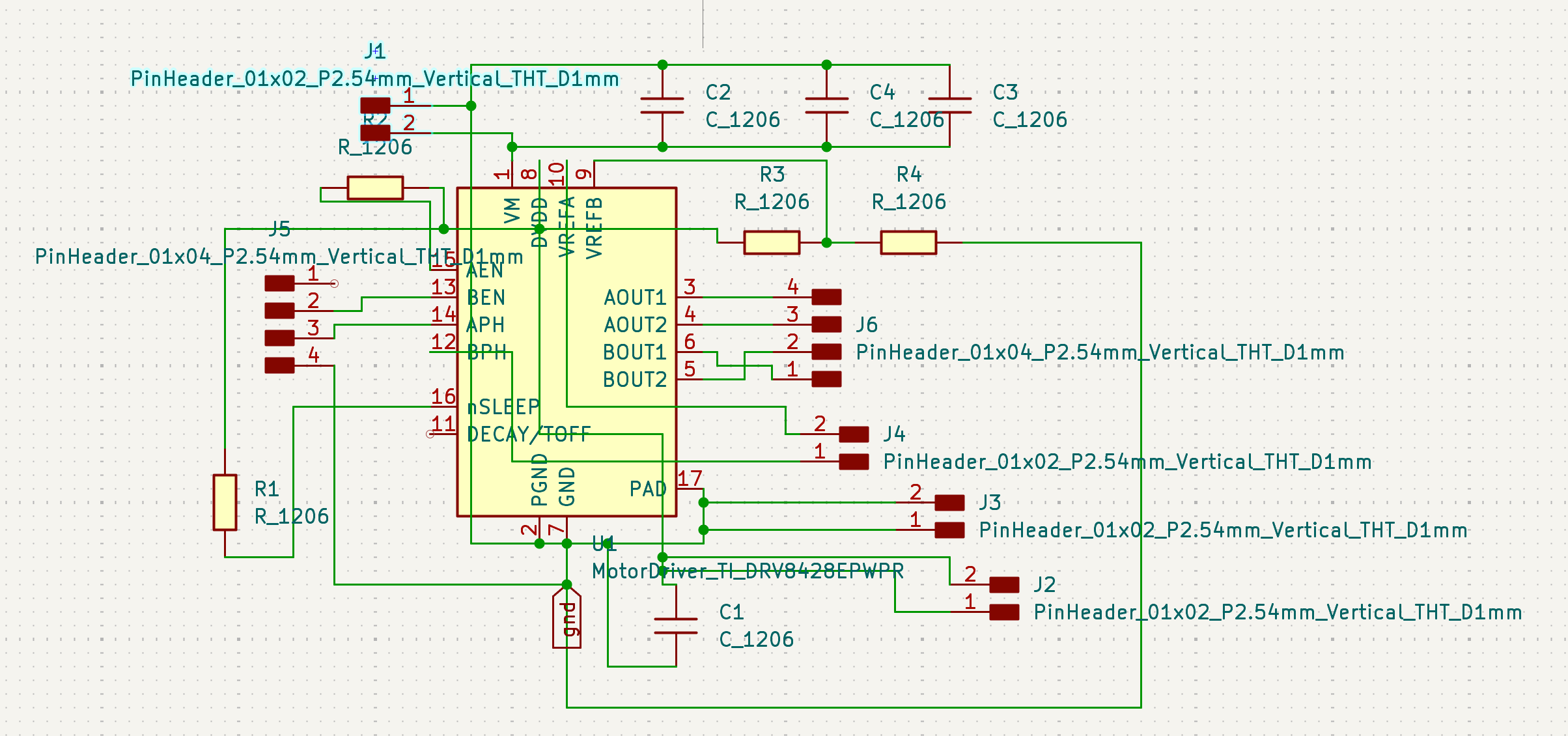
To be honest, this was so tiny, that I was not sure if I could even solder this properly. I then started to design the schematic with Anthony after going over the datasheet. I also learned about basics of the stepper motor and the 4 phase step pattern to drive the motor’s 4 pins. The DRV8428 makes it easy to control the motor, what we need to control is DIR, STEP, M1 and M0. STEP takes in a pulse - for each step, and DIR is puled high or low for the direction. M1 and M0’s state (hi, low, floating) determines the step size.
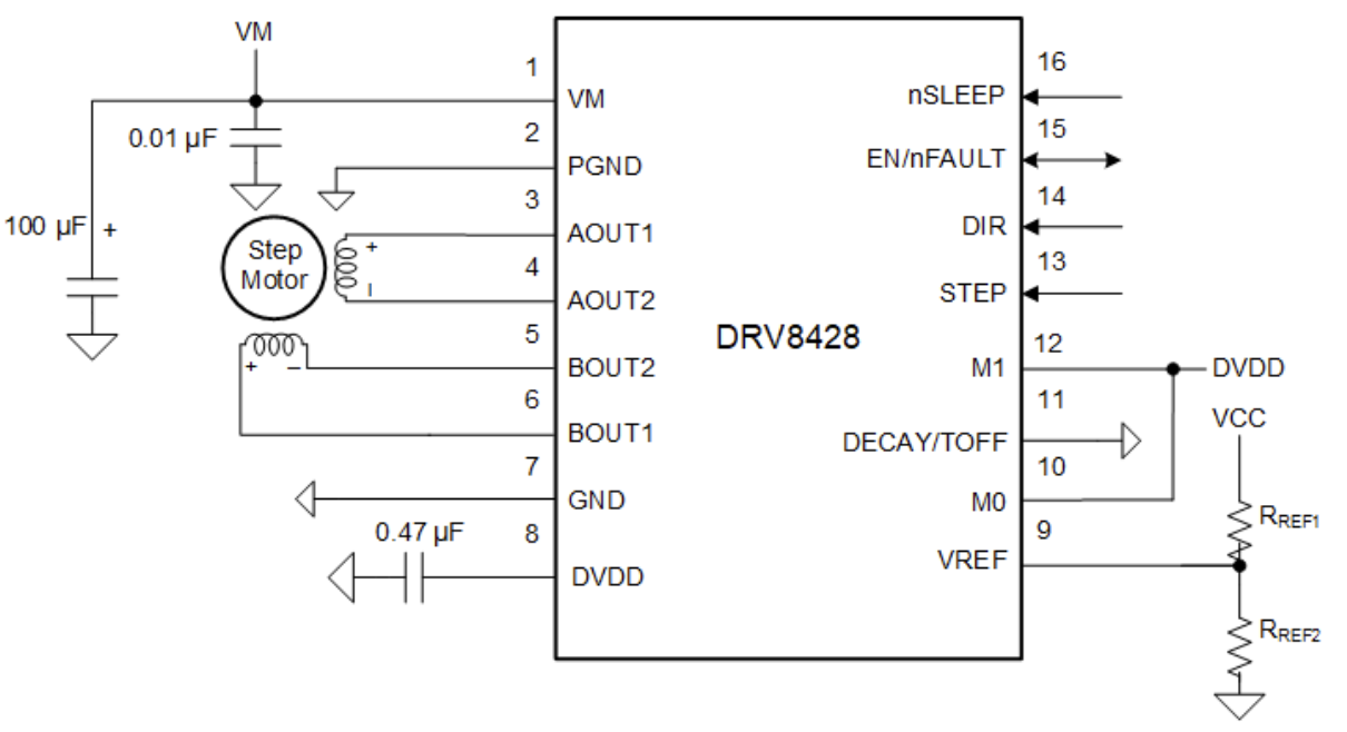
This is figure 8-1 from the datasheet. I followed most of it (this was also the main cause of my problems) to design the first version.
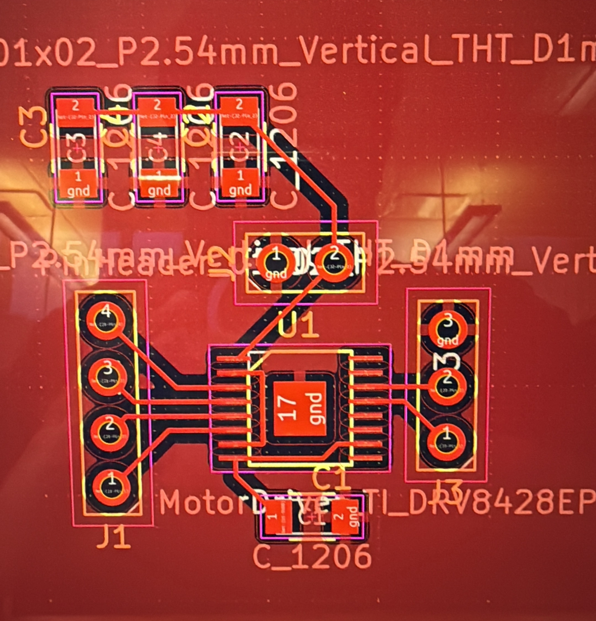
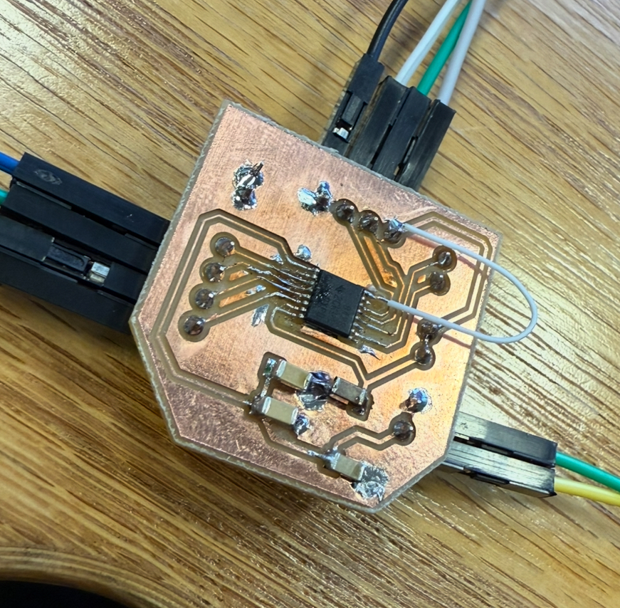
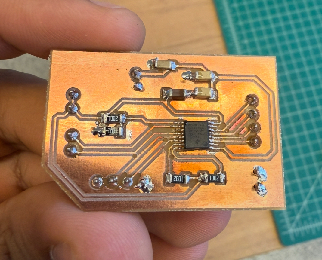
Anthony said I can use 2 10 uf capacitors in parallel instead of a 100uf one, and we replaced the .47uf with a 1uf. I think milled this board and soldered all the components
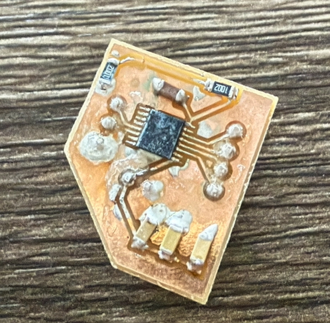
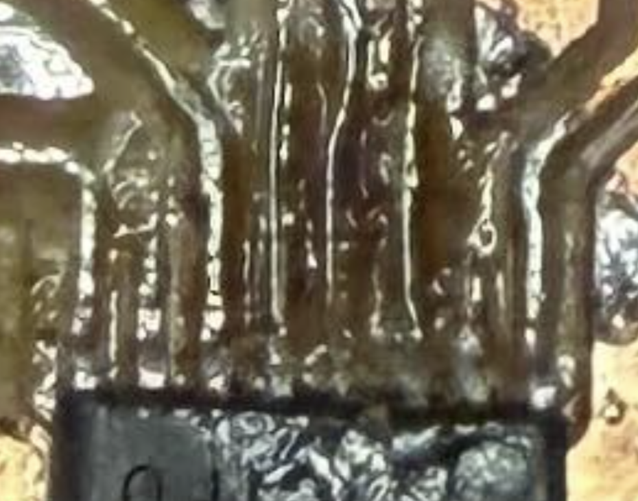
You might be wondering why it looks a bit gross with that layer covering everything, it turned out I didn’t solder the header pins properly where the black part was flush to the PCB. The gap caused the metal pin to poke through and break the trace. That’s why the trace that has the pin between it has solder because I fixed it and then took Gorilla gel glue and covered the whole board with it.
Then when I went home and tried to hook everything up - that trace popped out again!
Round 2
I was afraid of header pins now - and wanted to switch to screw terminals.
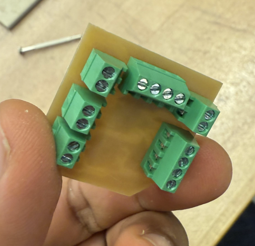
I thought this will be the final board and wanted to make M0 and M1 customizable so I added 3 screw terminals, one for M0,M1 and one for DVDD and one for Ground, such that I can connect M0,M1 to them in different configurations to change the step size.
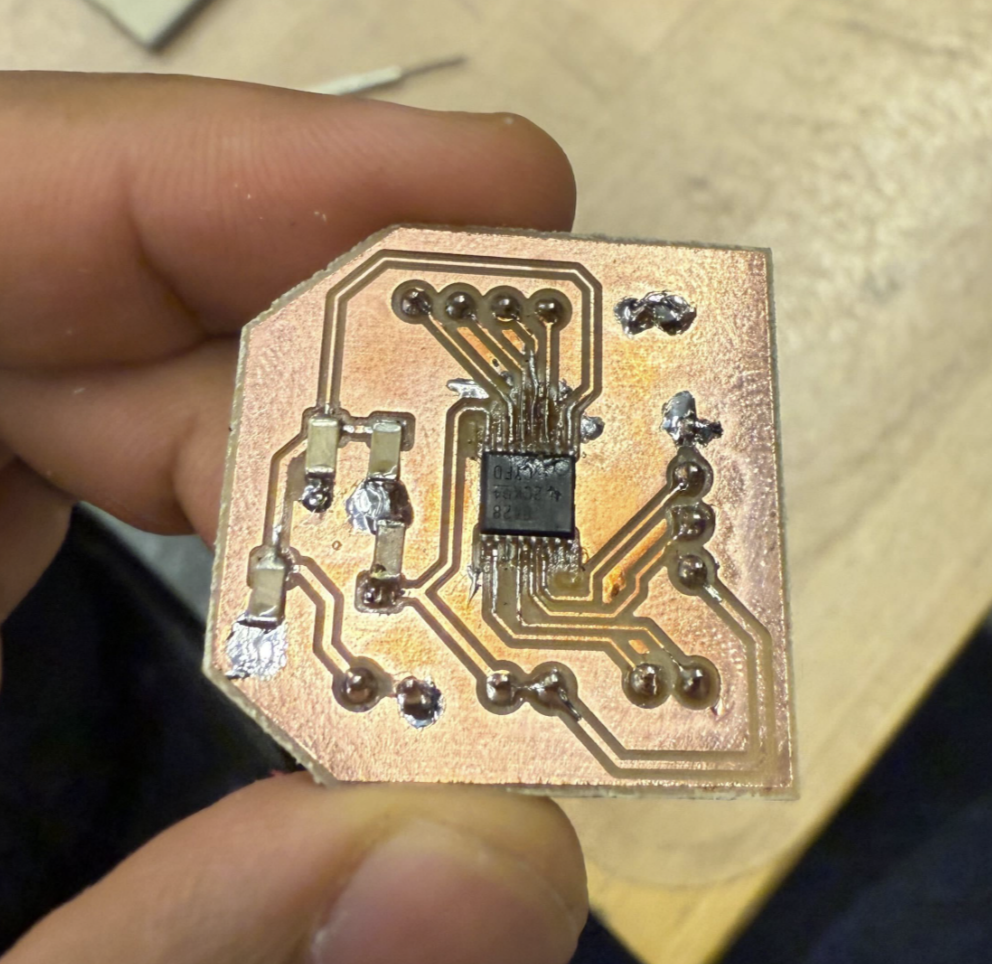
This board was the hardest soldering experience I had in my life. The traces to the motor controller partly broke so there was a gap between the legs of the IC and the trace. I had to then take a really thin copper wire from some scrap wire laying near the soldering station.
The microscope was my best friend for this.
After hooking VM and PGND to the power supply at 12 V and also the Xiao’s 5v both didn’t seem to work. I had no idea why, so I came back the next morning to meet Anthony.
Round 3
I sat with Anthony to debug this. The first mistake he pointed out was I didn’t connect nSleep, which needs to be at HIGH to enable the device. So we did a small hack.
That didn’t work. The motor wasn’t even hard to turn when everything was powered so there still was a fundamental issue. Then Anthony spotted I was inputting 3.3v into DVDD - which was wrong, DVDD just needed a capacitor connected to ground. Anthony had told me this before when we were first designing the schematic but I forgot - my bad.

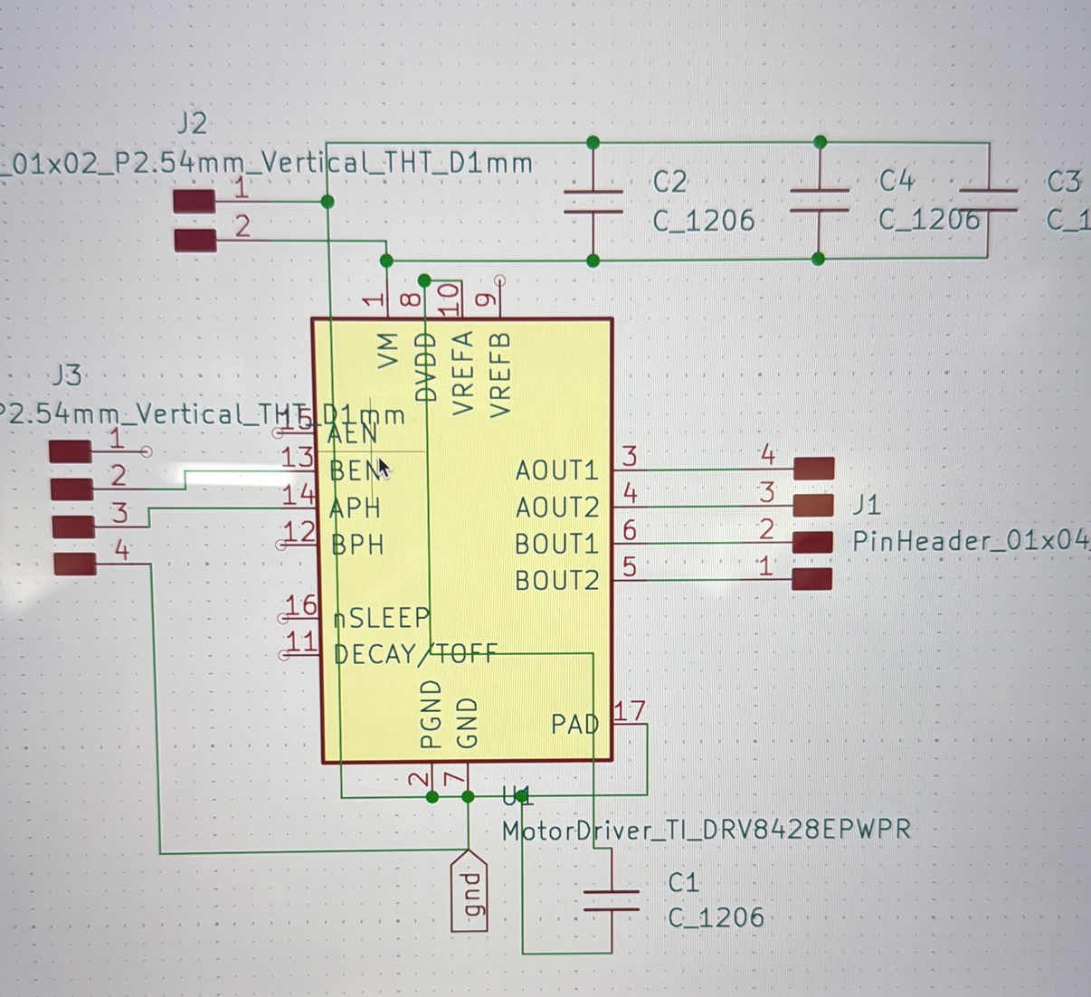
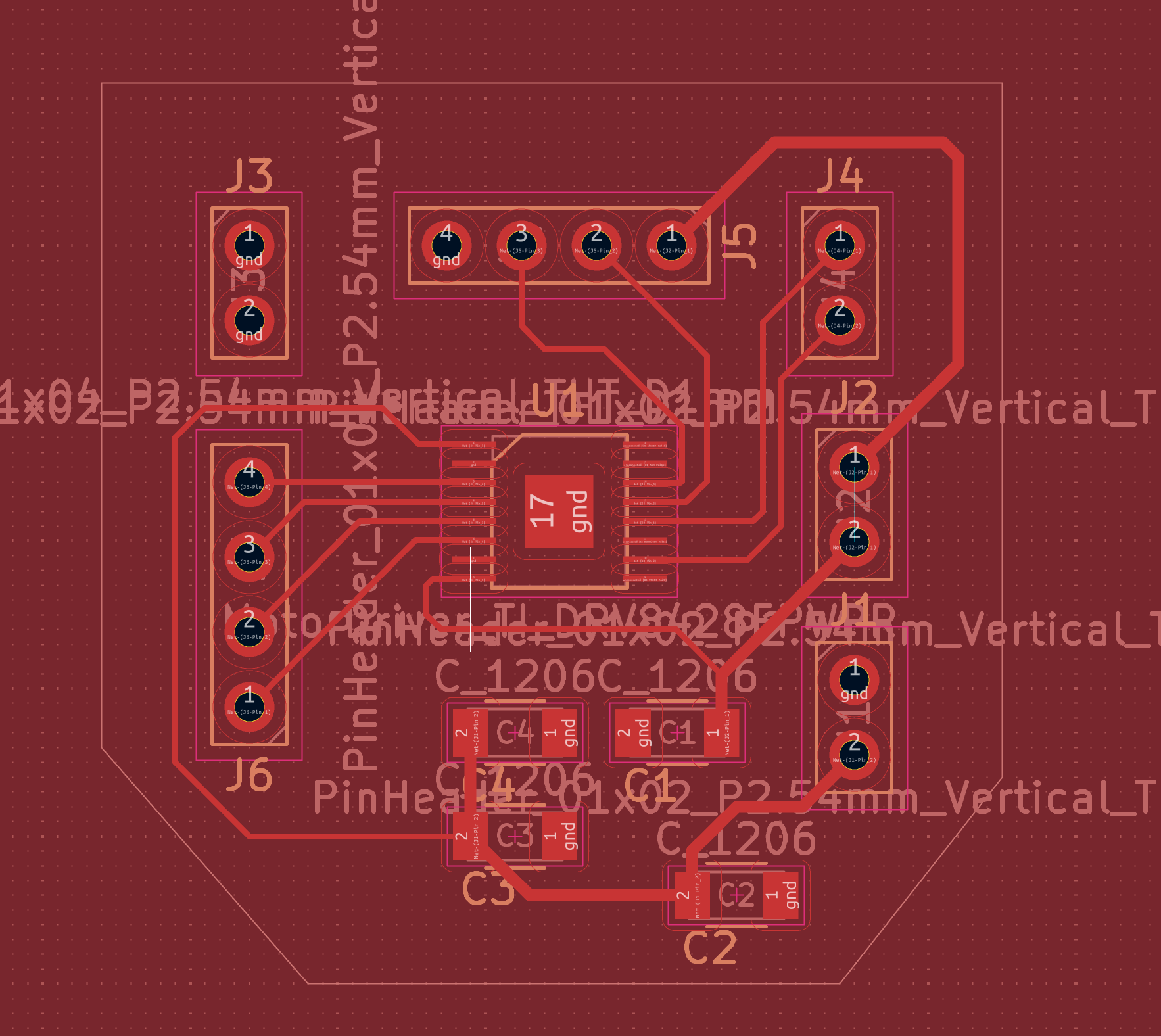
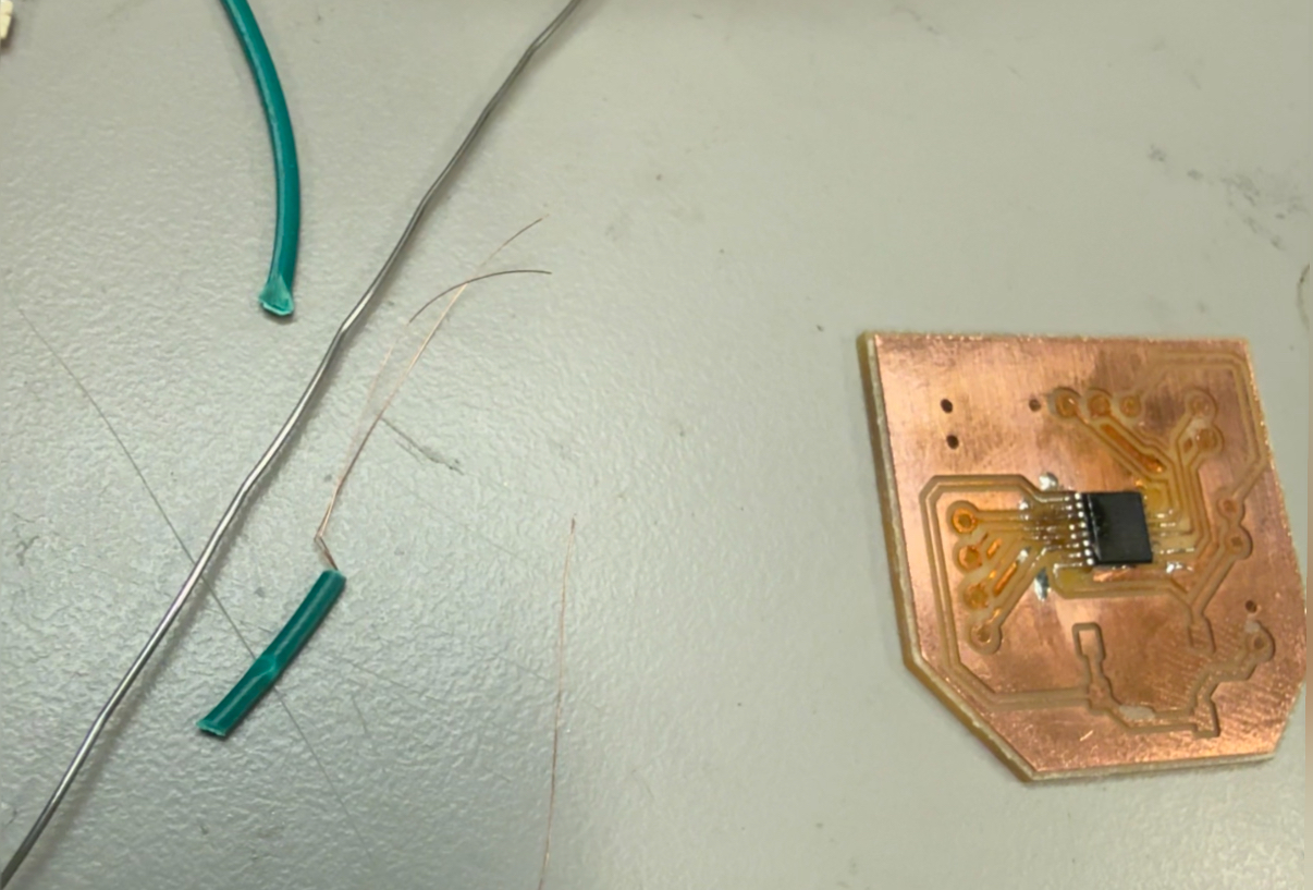
So now the board could have been fried. I also needed to connect VREF to a resistor divider (each resistor is a 10k) and Anthony explained how this sets the reference voltage. I then redesigned the schematic and the board. Both nSLeep and EN/nFAULT was connected to DVDD via a 10k resistor each. We also increased the trace width of the IC’s pad to .24 mm to prevent it from flaking off.
Soldering this time was smooth since all the traces were intact.
It still didn’t work…
All the connections looked good and there was no shorts, so then Anthony came up with a hypothesis nSleep was connected to DVDD - but the board needs to be on for DVDD to be HIGH - so its a circular issue. The way to circumvent this is directly pull nSleep HIGH via the 3.3 line from the xiao with a 10k resistor. And this is what I soldered.
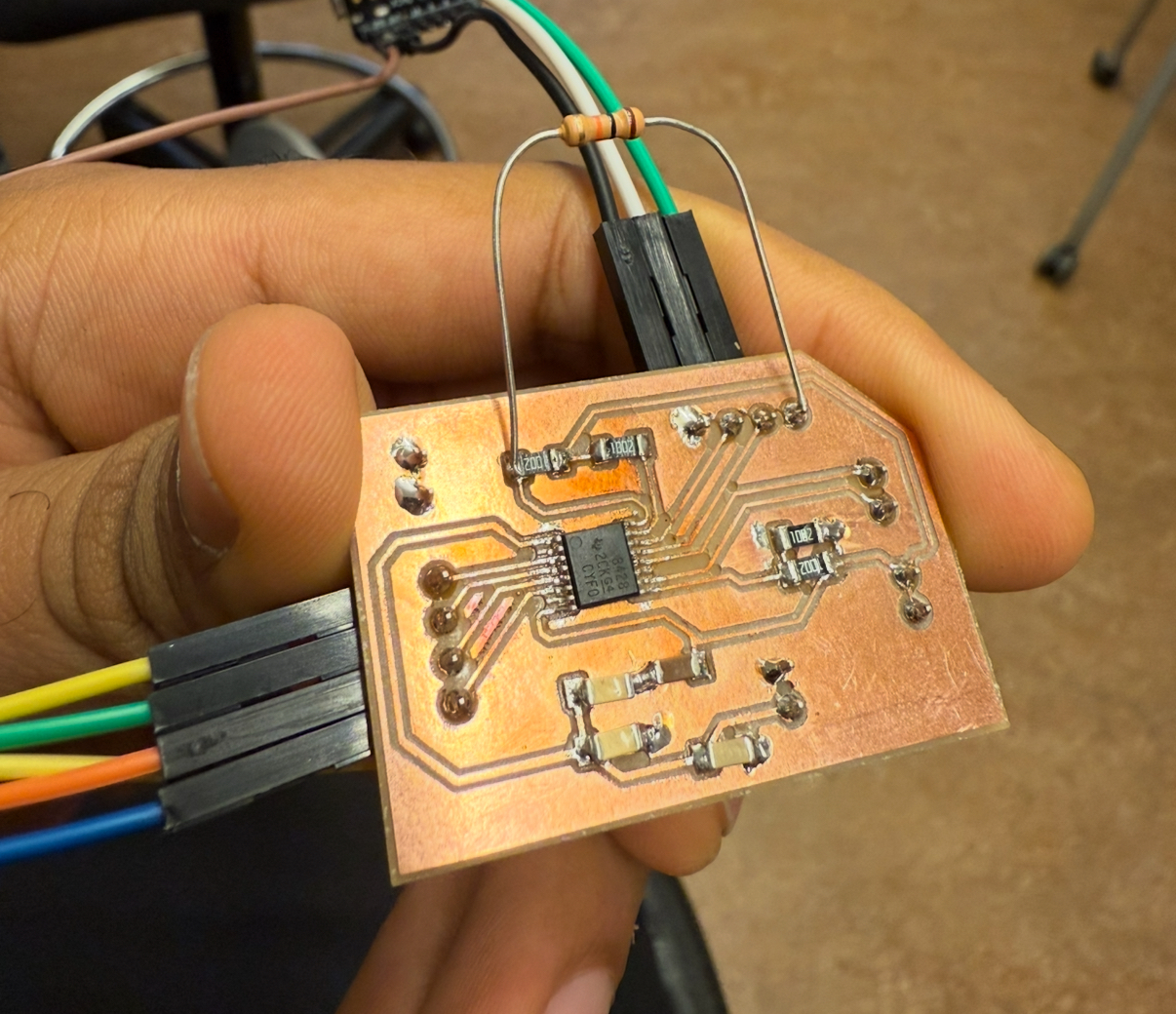
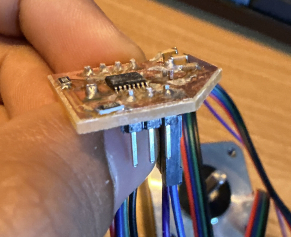
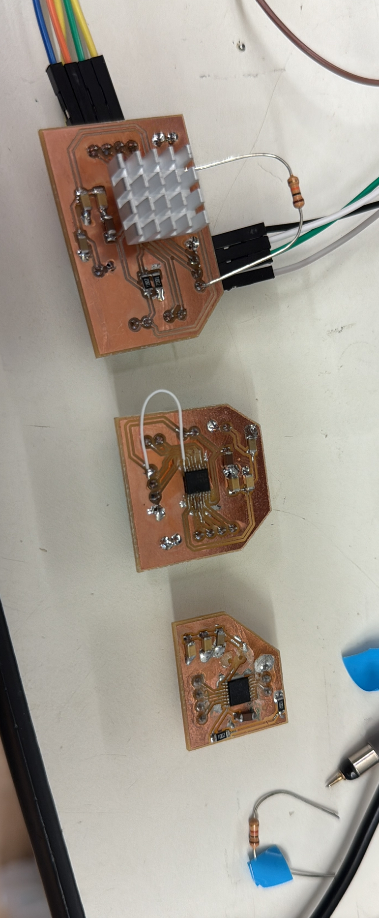
This worked! Until it didn’t fully, after a short while the motor started to twitch and then Anthony realized the IC was getting very hot and then we added a heat sink and I added another one on top to be super safe, and then it started to work continuously. In my next iteration I need to do better thermal dissipation.
The 3 generations.
Code:
// This is modified from the class code by Neil
// hello.DRV8428-D11C.ino
//
// DRV8428-D11C stepper hello-world
//
// Neil Gershenfeld 5/30/21
//
// This work may be reproduced, modified, distributed,
// performed, and displayed for any purpose, but must
// acknowledge this project. Copyright is retained and
// must be preserved. The work is provided as is; no
// warranty is provided, and users accept all liability.
//

#define DIR D0
#define STEP D1
#define DELAYHIGH 10
#define DELAYLOW 500

void setup() {
   digitalWrite(STEP,LOW);
   pinMode(STEP,OUTPUT);
   digitalWrite(DIR,LOW);
   pinMode(DIR,OUTPUT);
   }


void loop() {
      digitalWrite(STEP,HIGH);
      delayMicroseconds(DELAYHIGH);
      digitalWrite(STEP,LOW);
      delayMicroseconds(DELAYLOW);
   }
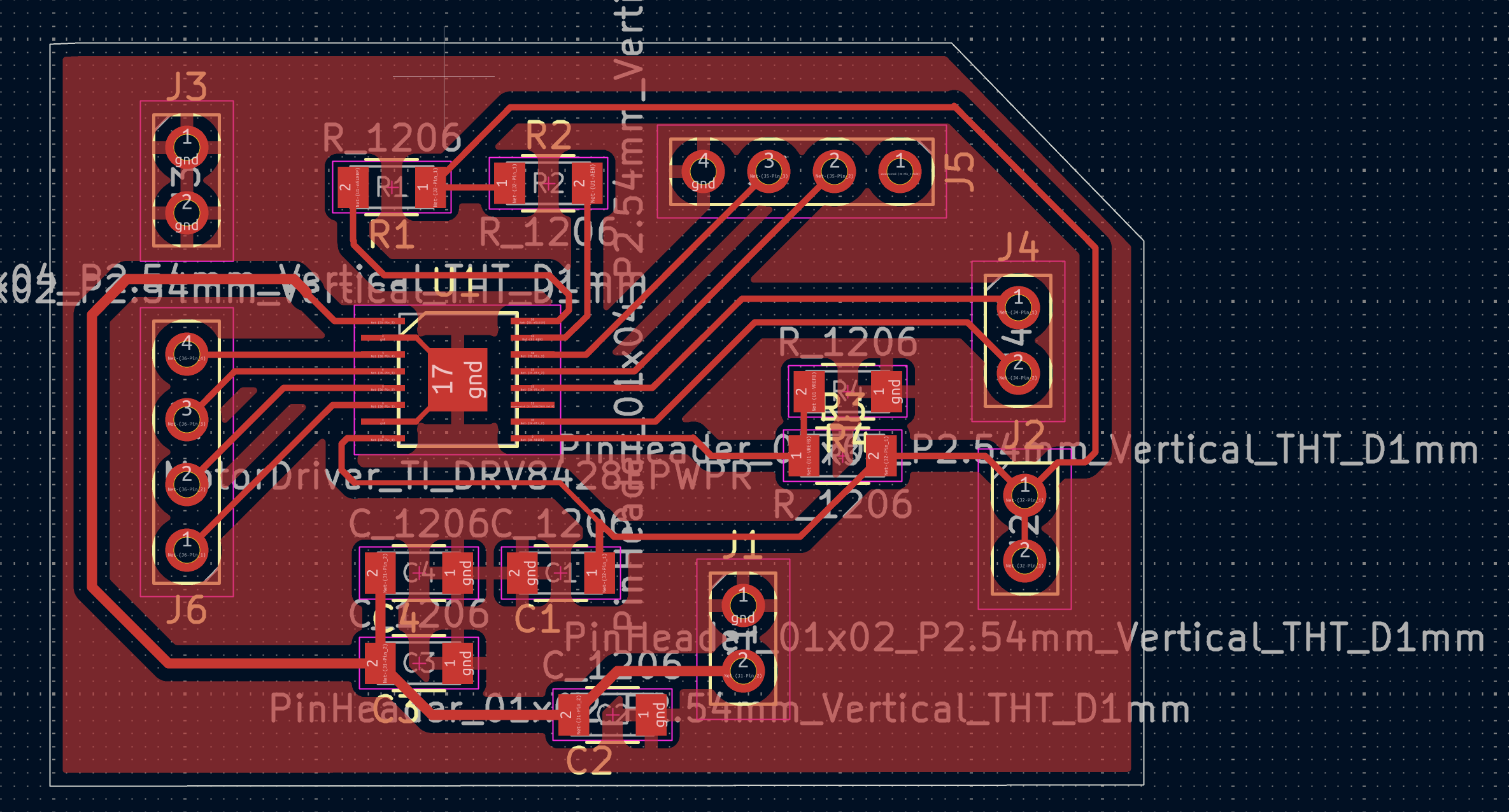
For the PCB files - I unfortunately somehow lost this version, but I made a more compact better one - with the same schematic for my final project - so the Kicad files are there.