Week 8 - Output Devices Group Assignment Summary
Measuring Power Consumption of Output Devices
Assignment Overview
This page summarizes the group assignment for Week 8, focusing on measuring power consumption of motors, servos, and stepper motors using adjustable power supplies and precision energy analyzers. We systematically investigated different motor types to understand their performance characteristics and when to use each type.
Group Assignment: Measuring Power Consumption of Output Devices
Measuring power consumption of motors, servos, and stepper motors using adjustable power supplies and precision energy analyzers to understand performance characteristics and when to use each type.
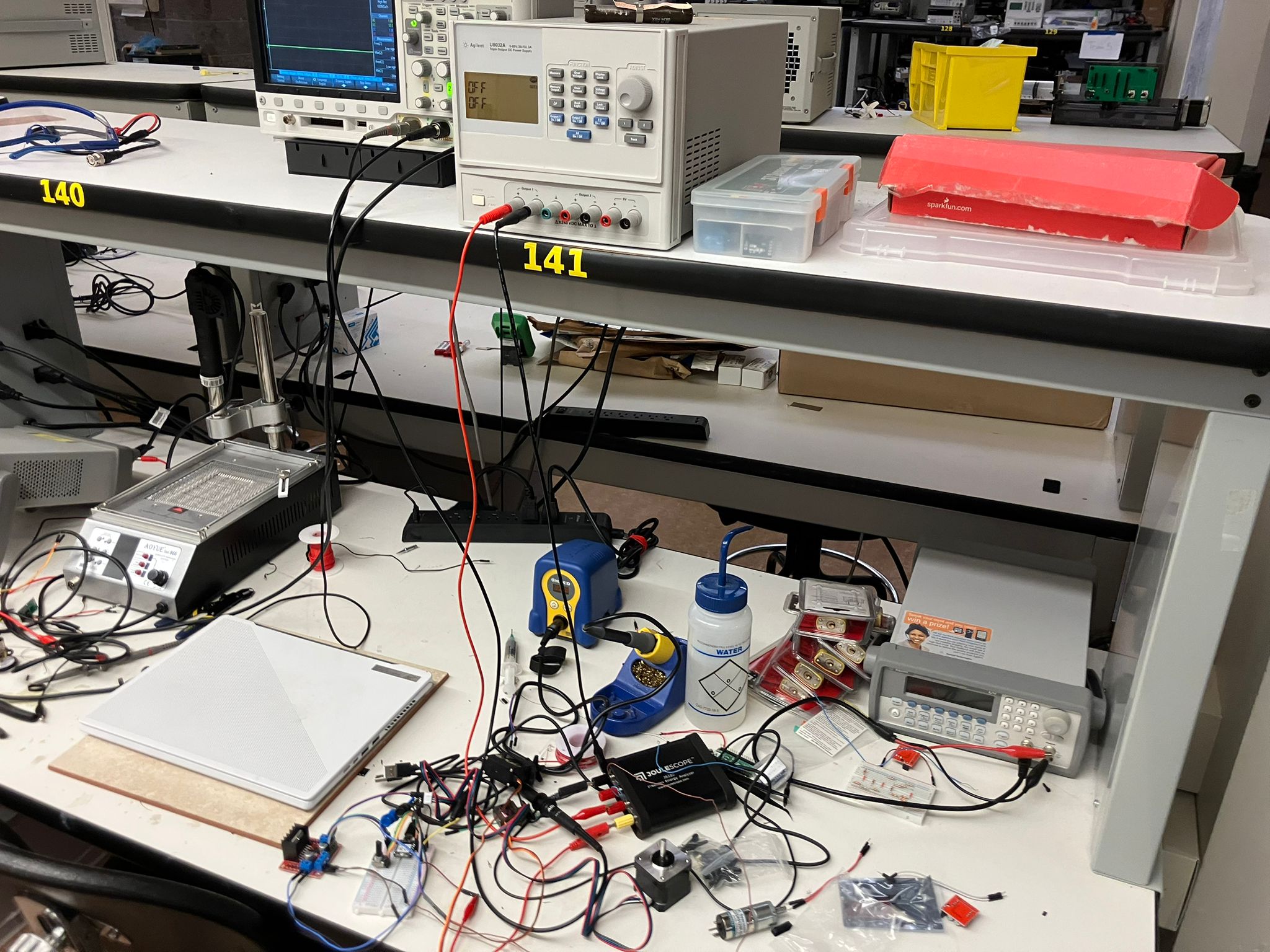
Measurement Setup
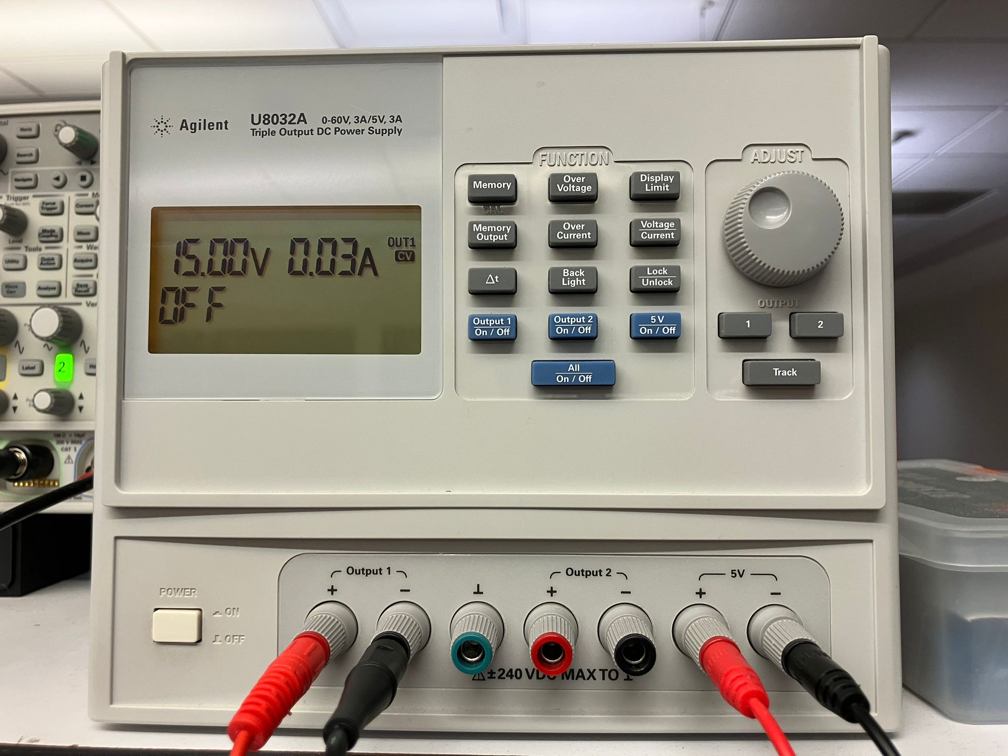
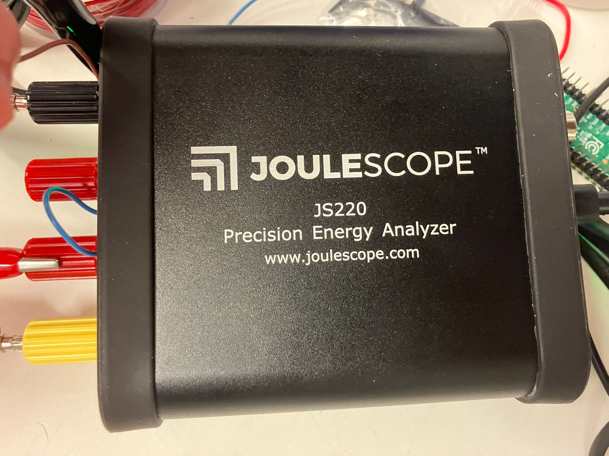
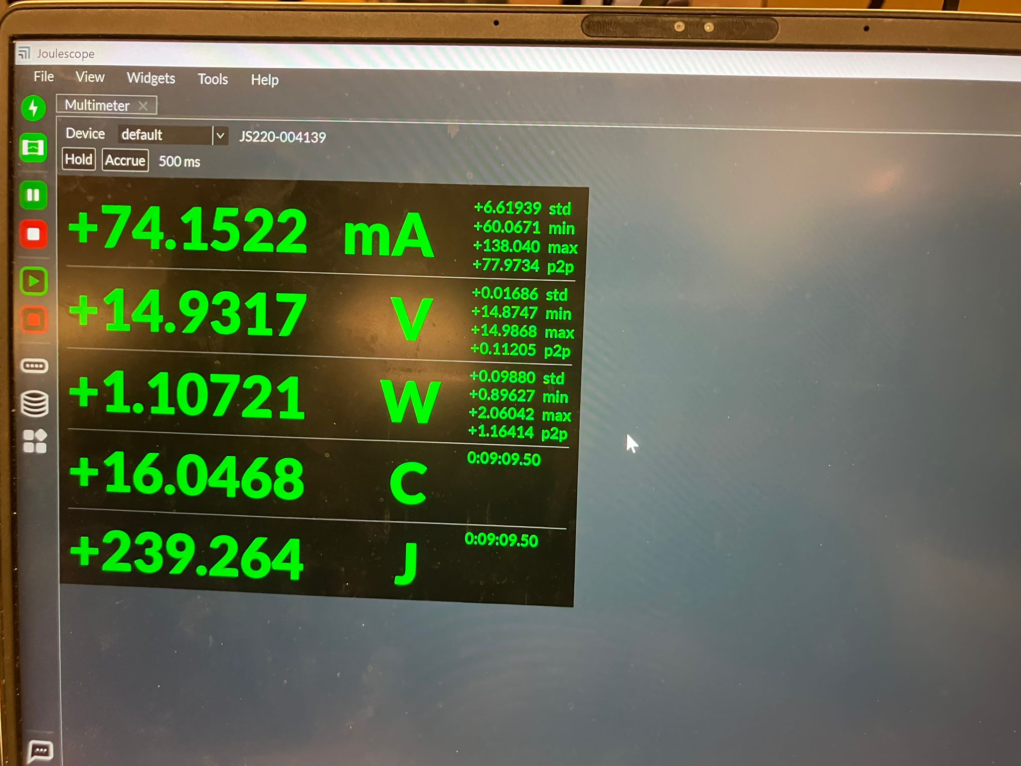
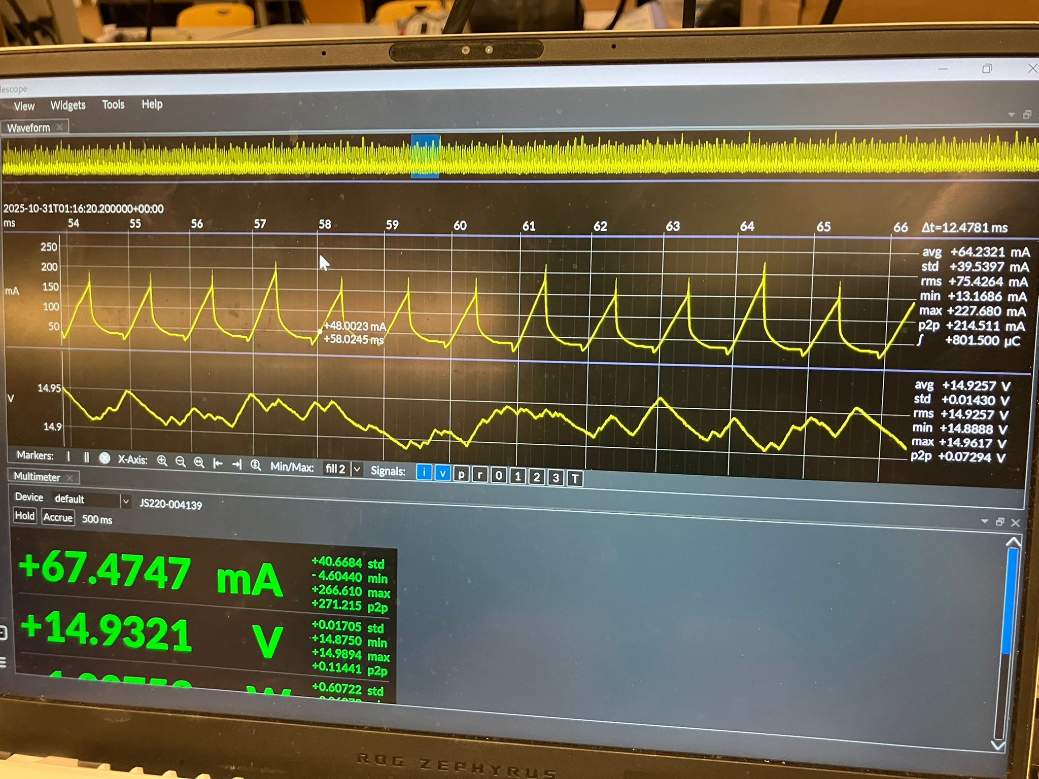
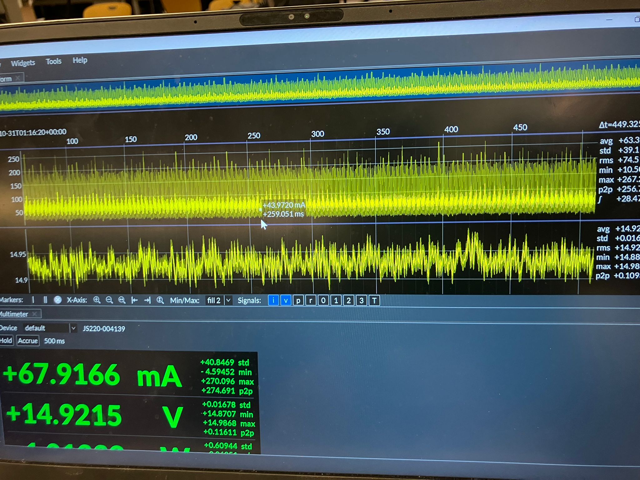
We used an adjustable power supply set to 15V and measured quiescent power consumption of 450 mW (0.03 A, where P=IV) before connecting any motors. Power measurements were conducted using the Joulescope (JS220) Precision Energy Analyzer to measure current, voltage, power, charge, and energy in real-time.
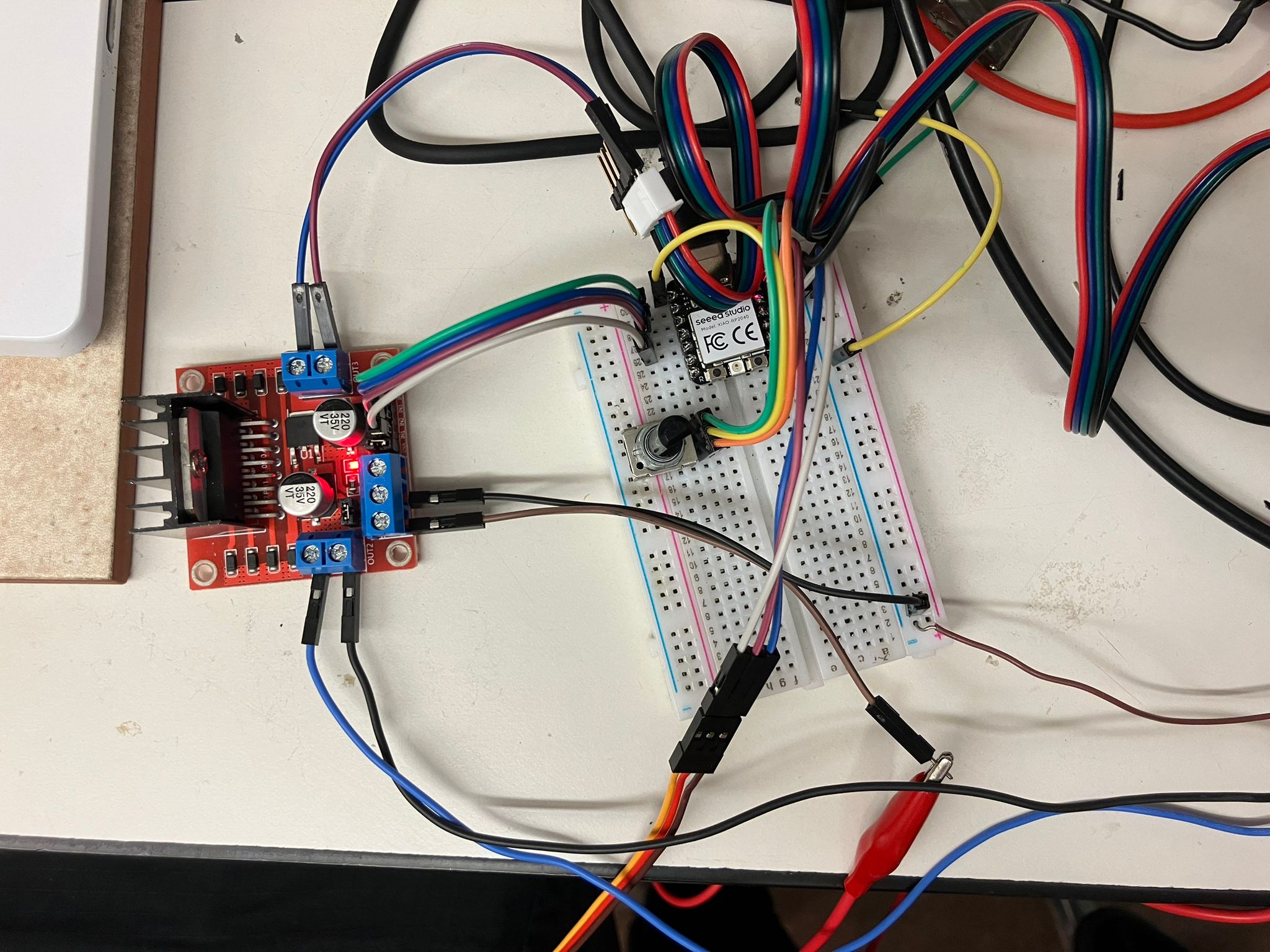
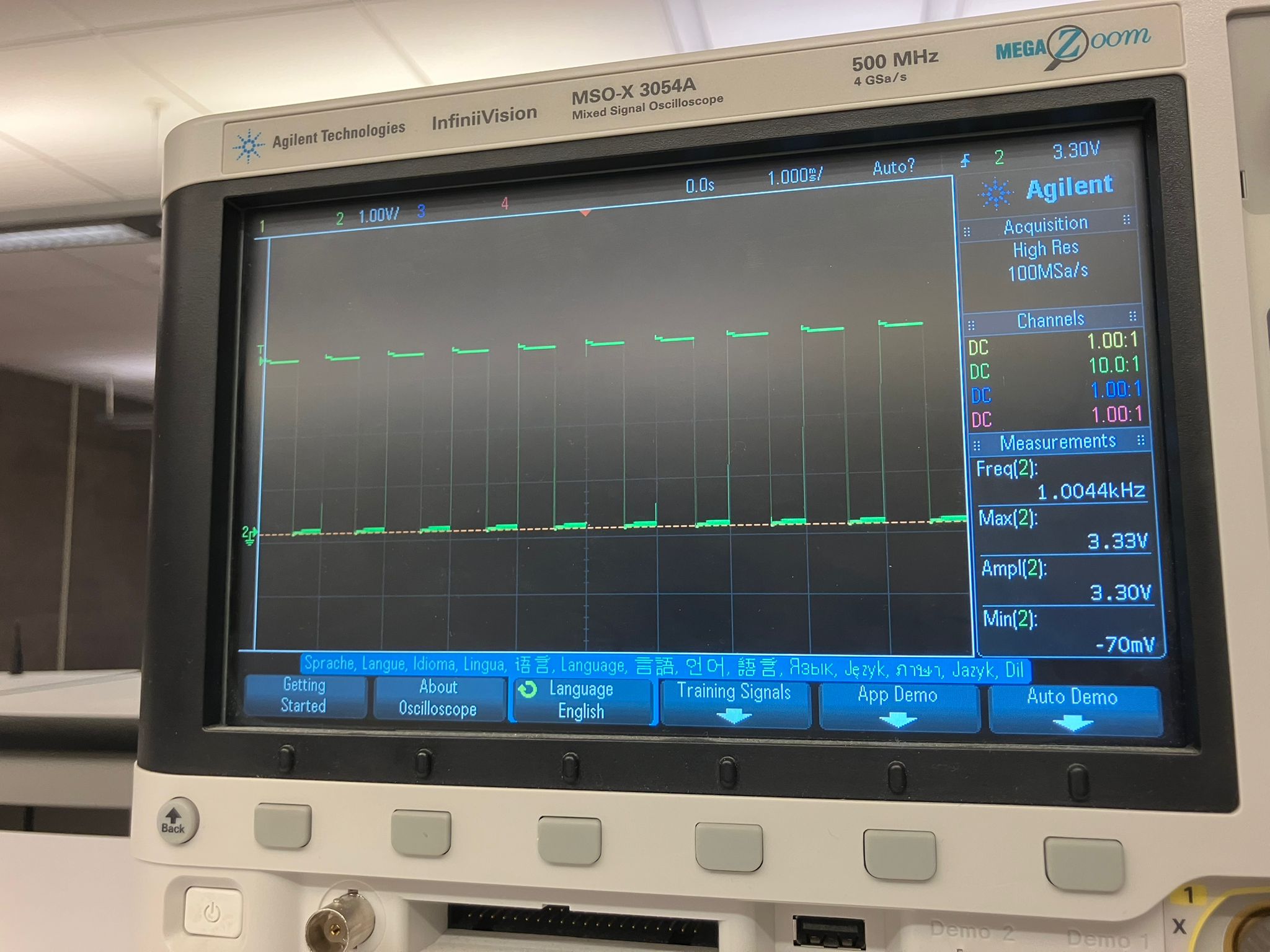
Using a potentiometer to change motor speed, we observed that below a certain threshold, the motor doesn't have enough power to spin (no mechanical work, just electrical losses). Above this threshold, speed increases with power. The dI/dt (rate of current change) cannot change instantly—it takes time. The PWM signal from the microcontroller (roughly 50% duty cycle) is smoothed after passing through the motor driver, with more linear behavior on the rising edge than the falling edge.
Motor Comparison Results
All motors tested at 15V supply, 2A current limit, with the same potentiometer value for comparison. The potentiometer determines speed and power for DC motors, and position for servos.
DC Motors (Voltage-Controlled)
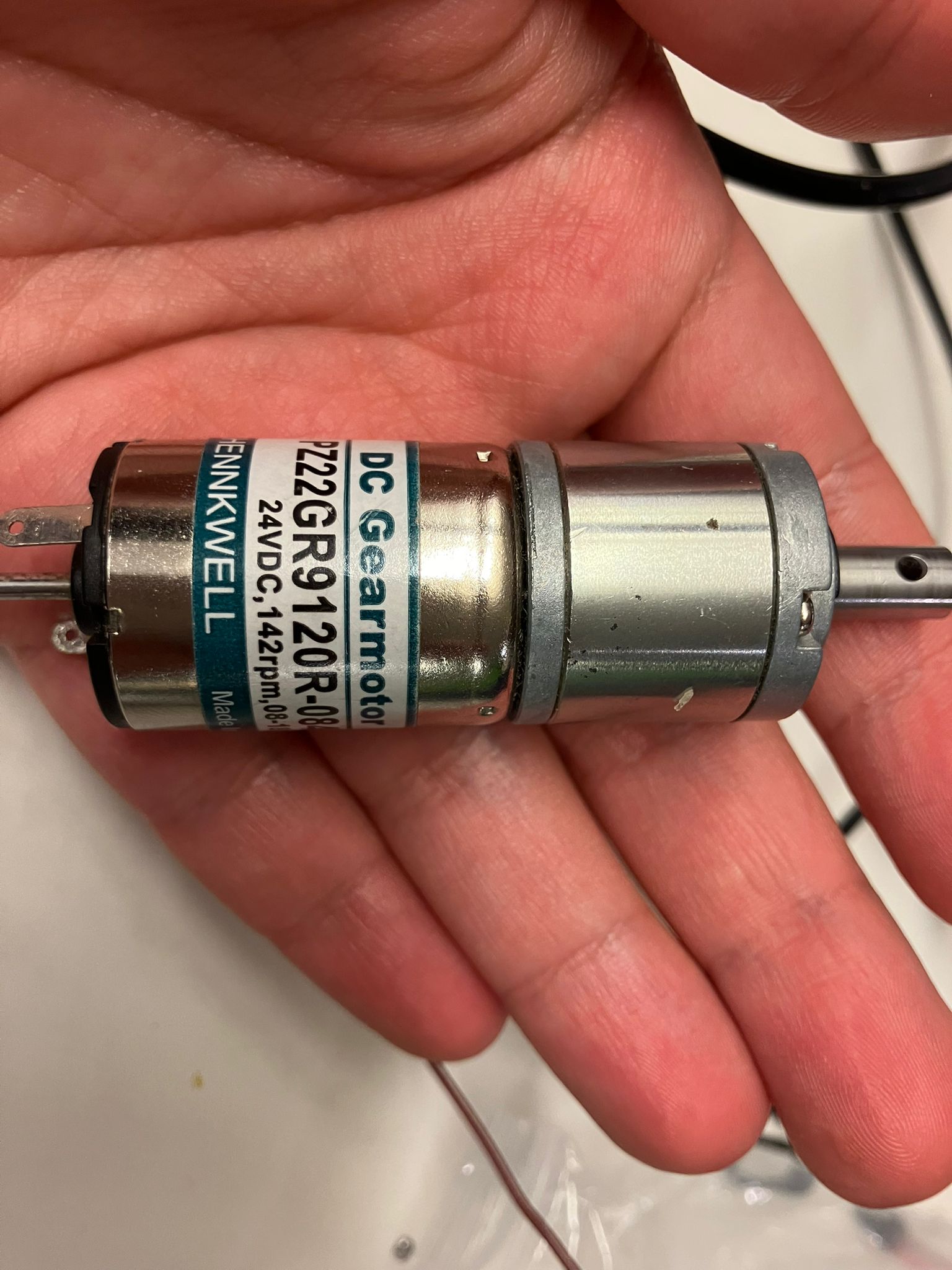
DC Brushed Motor (Large)
Characteristics: Low-speed, high torque, no positional control
- Current: 57 mA
- Voltage: 14.49 V
- Power: 0.8 W
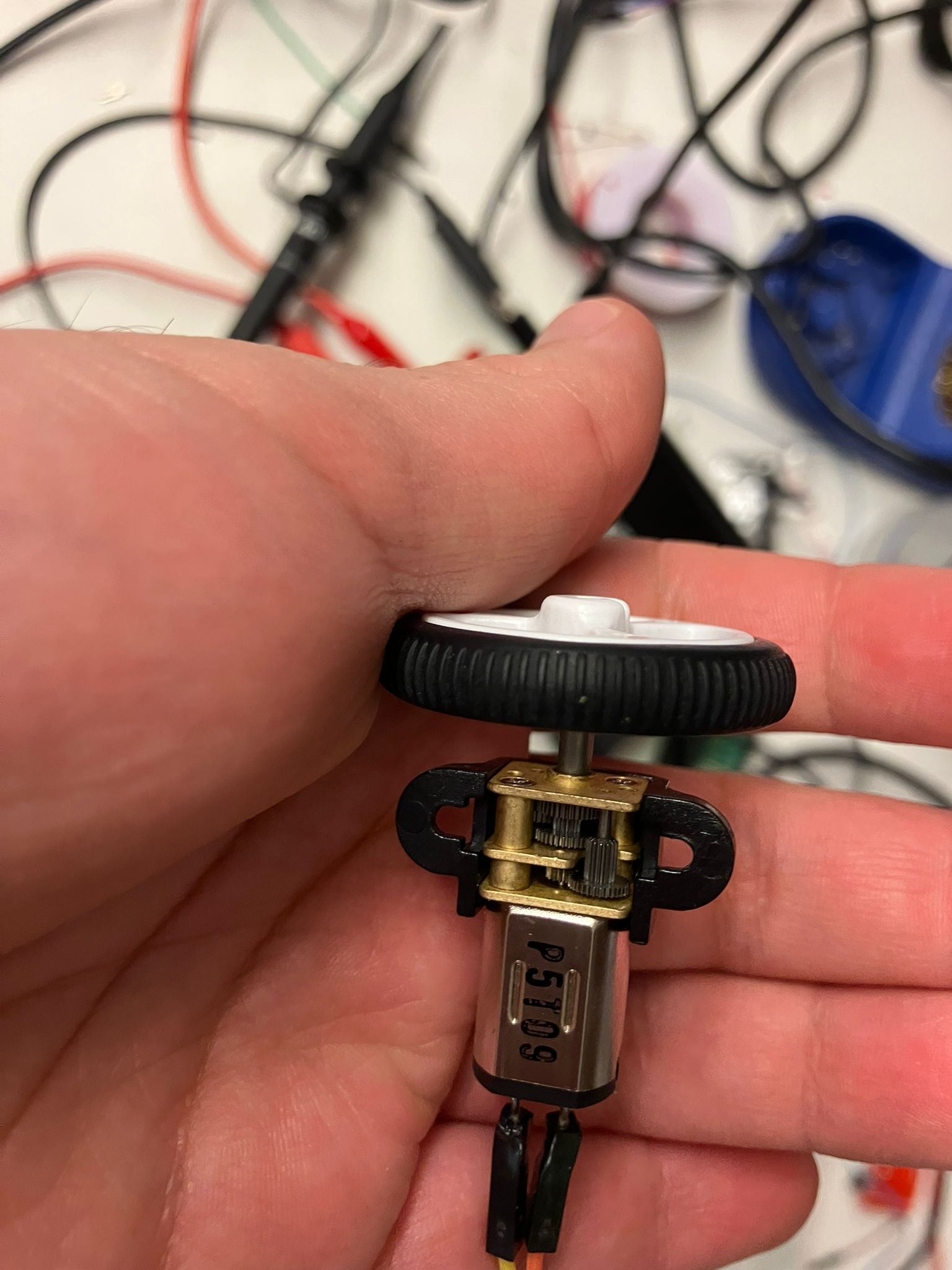
DC Brushed Motor (Small)
Characteristics: High speed, medium torque, no positional control
- Current: 0.34 A
- Voltage: 14.47 V
- Power: 4.86 W
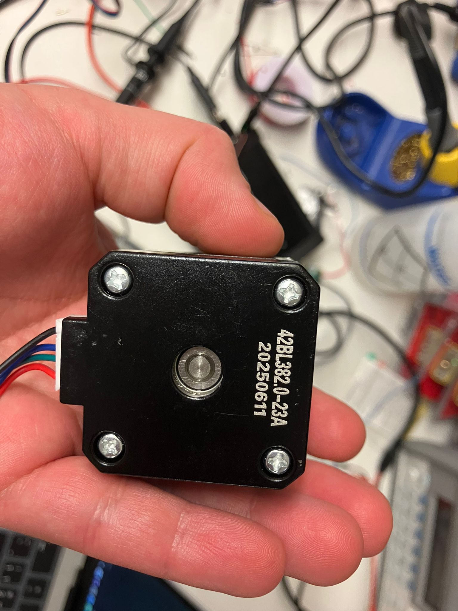
DC Stepper Motor (Current-Controlled)
Characteristics: Medium speed, medium torque, zero absolute positional control (relative positioning only)
- Current: 2.0 A
- Voltage: 10.93 V
- Power: 22.33 W
Servo Motors (5V Supply, Position-Controlled)
All servos tested at 5V supply, 2A current limit. Potentiometer determines position; power consumption remains relatively constant.
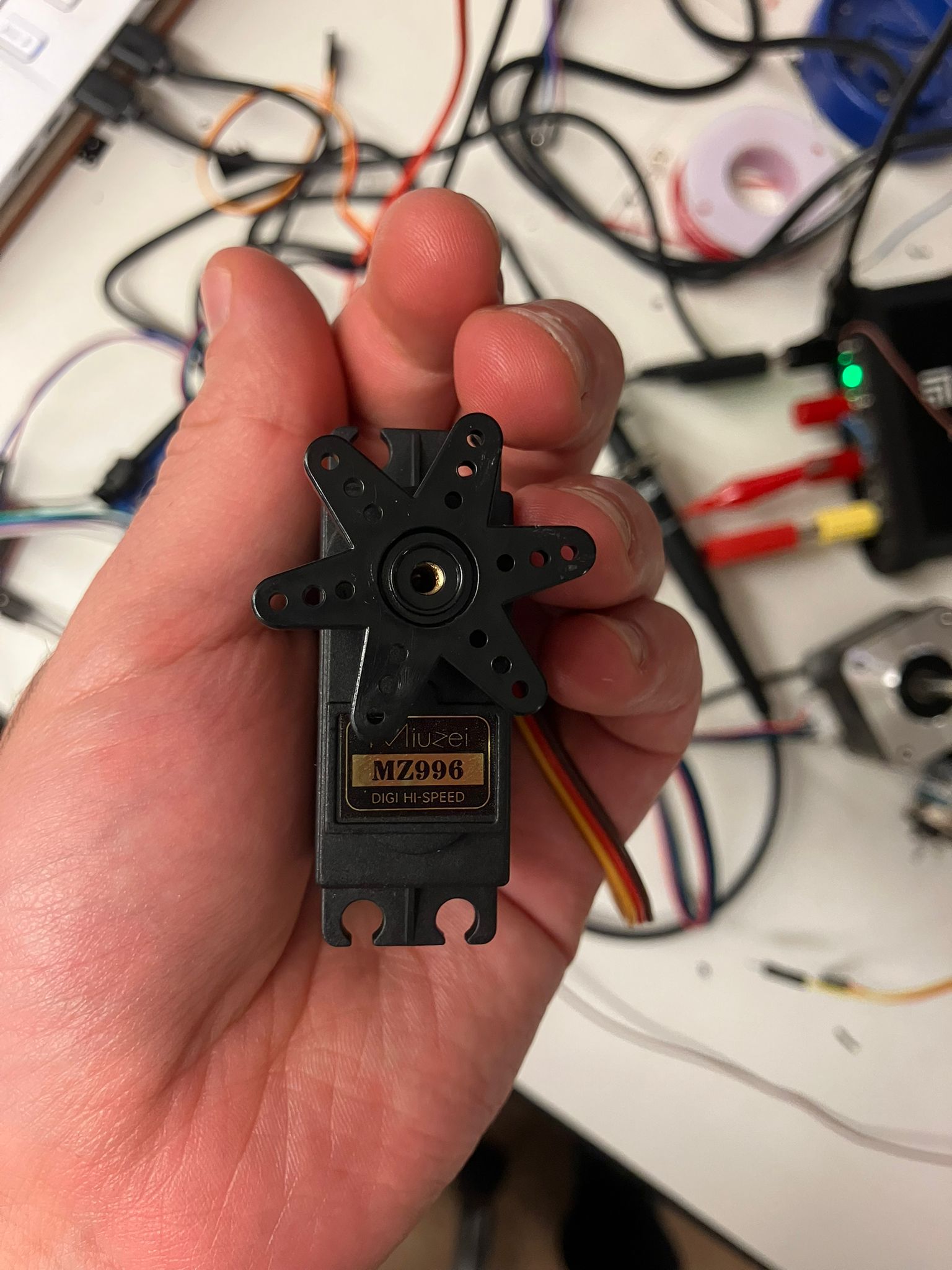
Servo Motor (Large)
Characteristics: Absolute positional control, slower response
- Current: 10.6 mA
- Voltage: 4.99 V
- Power: 53.4 mW
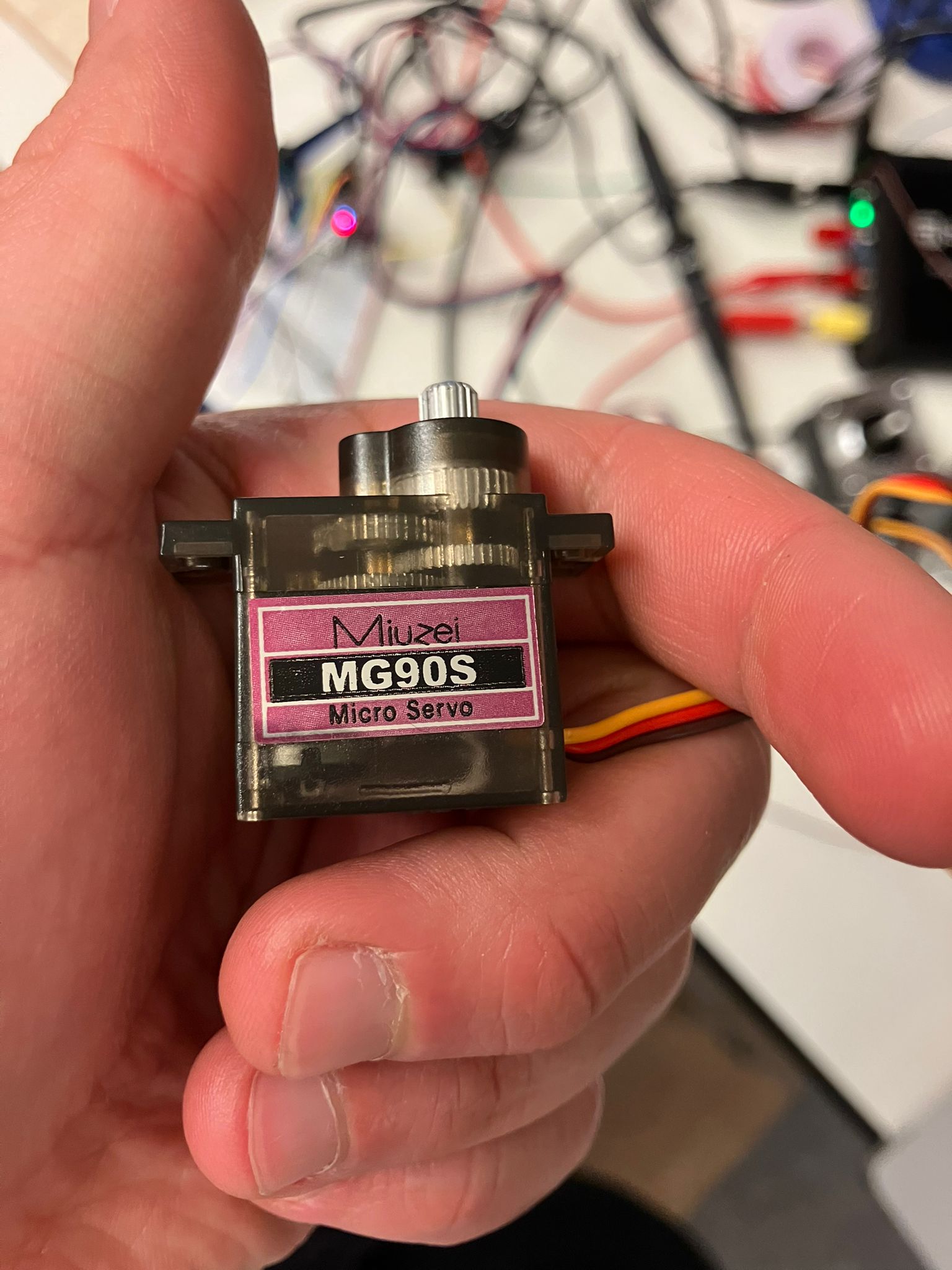
Servo Motor (Micro)
Characteristics: Absolute positional control, slower response, lower power
- Current: 5.04 mA
- Voltage: 4.99 V
- Power: 25.05 mW
Motor Comparison Summary Tables
Constant Voltage Comparison (15V Supply, 2A Current Limit)
DC brushed and stepper motors tested at 15V. Potentiometer controls speed for brushed motors, and step rate for stepper motor.
| Motor Type | Size | Current | Voltage | Power | Characteristics |
|---|---|---|---|---|---|
| DC Brushed | Large | 57 mA | 14.49 V | 0.8 W | Low-speed, high torque, no positional control |
| DC Brushed | Small | 0.34 A | 14.47 V | 4.86 W | High speed, medium torque, no positional control |
| Stepper | N/A | 2.0 A | 10.93 V | 22.33 W | Medium speed, medium torque, relative positioning only |
Constant Current Comparison (5V Supply, 2A Current Limit)
Servo motors tested at 5V. Potentiometer controls position; power consumption remains relatively constant regardless of position.
| Motor Type | Size | Current | Voltage | Power | Characteristics |
|---|---|---|---|---|---|
| Servo | Large | 10.6 mA | 4.99 V | 53.4 mW | Absolute positional control, slower response |
| Servo | Micro | 5.04 mA | 4.99 V | 25.05 mW | Absolute positional control, slower response, lower power |
Summary: When to Use Each Motor Type
- DC Brushed Motors: Simple applications requiring variable speed and torque, where positional control is not needed
- Stepper Motors: Applications requiring precise relative positioning with medium power consumption
- Servo Motors: Applications requiring absolute positional control with low power consumption, especially in battery-powered systems
Reference Materials
Source: MIT HTMAA Week 8 Group Assignment
Detailed documentation of output device power consumption measurement and motor comparison analysis
Full Assignment Details
For complete details on the Week 8 group assignment, including comprehensive power consumption measurements, detailed motor comparison tables, and complete analysis results, please visit the full assignment page.
🔗 View Full Week 8 Group Assignment DetailsSpecial Thanks to Our Section
We would like to express our sincere gratitude to all members of our section for their invaluable collaboration throughout this group assignment. Your contributions were essential to the success of this comprehensive output device power consumption analysis project.
Collaboration Activities
- Power measurement and energy analyzer operation
- Motor testing and characterization
- Power consumption analysis
- Measurement technique documentation
Knowledge Sharing
- Joulescope energy analyzer operation and setup
- Motor characteristics and power measurement methodologies
- Output device selection and application guidelines
- Embedded systems power management
This collaborative effort demonstrates the power of teamwork in technical education and hands-on learning. The collective knowledge and shared experiences significantly enhanced our understanding of output device power characteristics and measurement techniques.
References
- Output Device Power Analysis
Comprehensive guide to measuring and analyzing power consumption of motors and actuators - Energy Analyzer Operation
Professional measurement equipment usage and power analysis methodologies - Motor Selection
Best practices for selecting appropriate motor types for different applications - Power Management
Current limiting, voltage regulation, and power consumption optimization techniques - Embedded Systems Design
Guidelines for designing efficient output device interfaces
Ethical AI Use
Documentation of AI tool usage for this week's group assignment summary and website development work.
Week 8 - Output Devices Group Assignment Summary Development
This session covers the development of the Week 8 page for the output devices group assignment, including content structure, technical documentation, and comprehensive coverage of power consumption measurement processes.
AI Development Documentation
Complete development transcript documenting the AI-assisted creation of the Week 8 group assignment page, including content structure, technical documentation, and website development process.
Key AI Activities
- Content Structure
Creation of comprehensive HTML structure for output device power consumption documentation - Technical Documentation
Development of detailed sections covering power measurement and motor comparison techniques - Process Integration
Implementation of output device characterization and measurement workflow information - Navigation Integration
Addition of Week 8 link to main index page for seamless course navigation - Image Integration
Integration of key images and videos from week8groupassignment folder with proper styling and captions - Link Integration
Addition of external link to full Week 8 assignment details with proper accessibility attributes
AI Tools Used
- Cursor AI
Code generation, content structuring, and website development assistance - Technical Content Generation
Creation of comprehensive output device power consumption documentation - Website Design
Implementation of consistent styling and responsive layout - Content Integration
Seamless integration of Week 8 content into the page structure - Media Processing
Integration and styling of images and videos with proper responsive layouts