HTMAA 25
home about me final projectI’ve built a lot of little parts for quite practical things, so I wanted to make something more “useless” and whimsical. My main want:
Some secondary wants:
I was juggling quite a few different ideas in my head, before someone suggested to me that I could make something that shoots. What’s something fun that shoots? A peashooter!
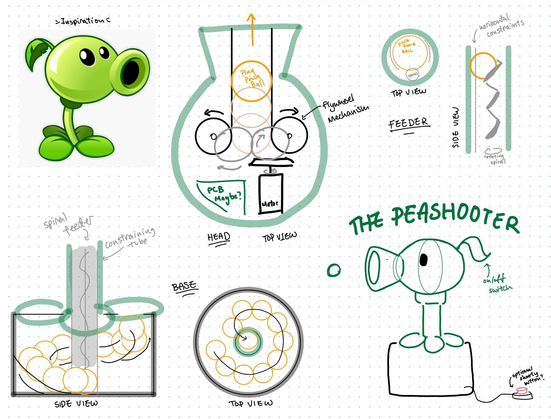
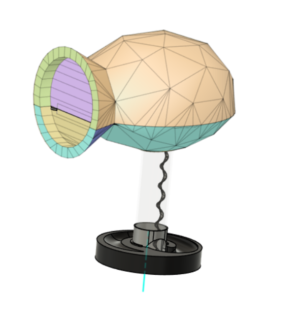
The overall design process can then be seen from my week 1 documentation. Here is my v1 CAD:
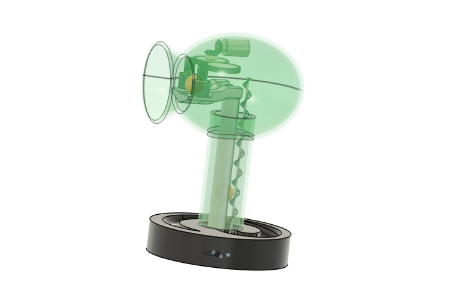
It’s not small, it’s barely disassemblable, but I hope it will pass physically robust - everything delicate is encased, and the shell seems easy to make sturdy.
It definitely has moving parts.
This might have to largely be 3D printed. I’m thinking I could CNC-mill the base out of wood, though, which would make it more organic (suitable for a plant) and sturdy. Leaves and other decorations I think would be cool to lasercut out of clear green acrylic, and heat-gun into shape. Ping pong balls I will purchase.
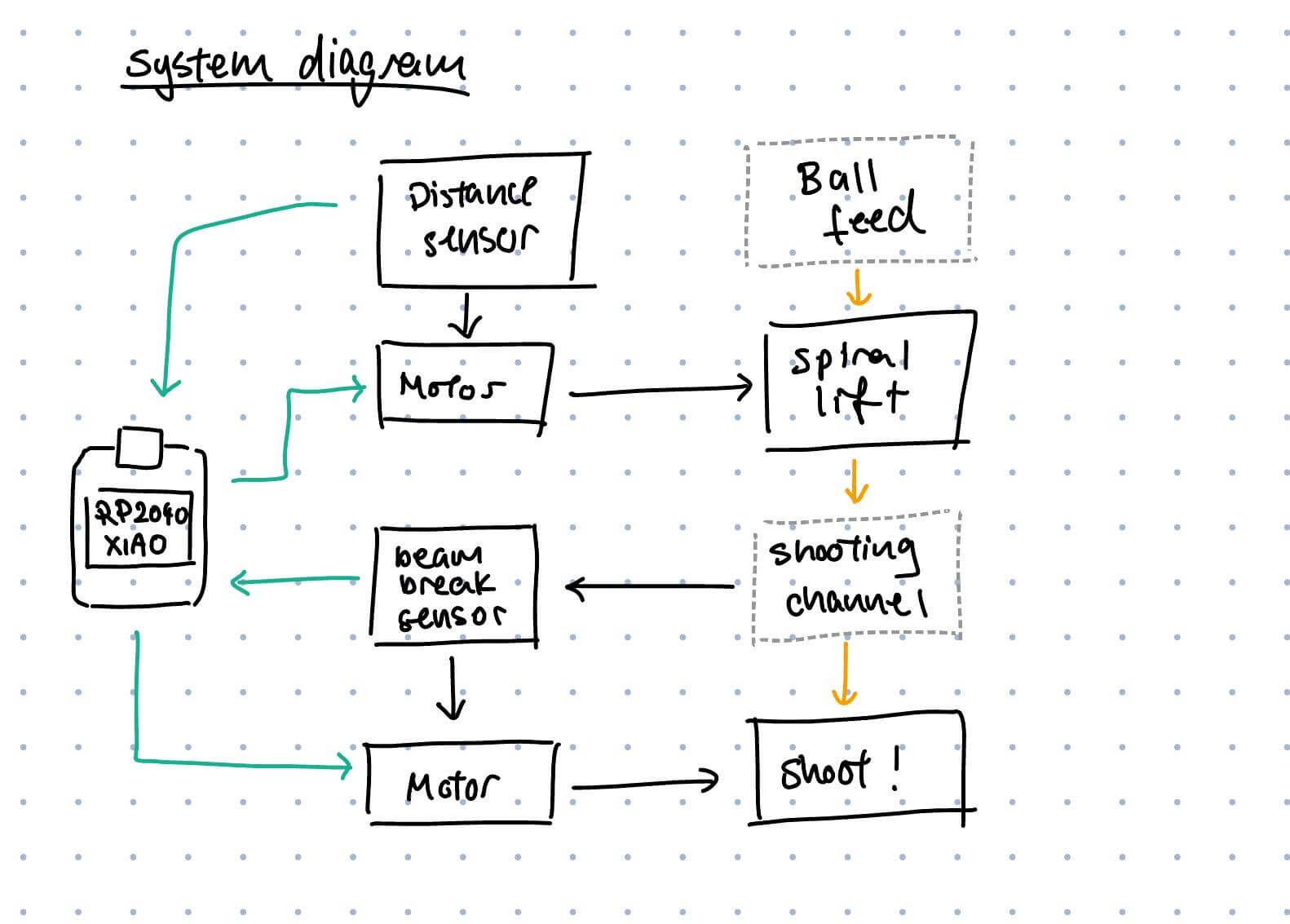
Anyways, system diagram!
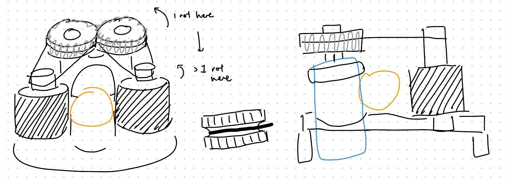
A gear chain might have been my first idea, but it likely wasn’t going to be the best one. I also sketched out the following mechanisms:
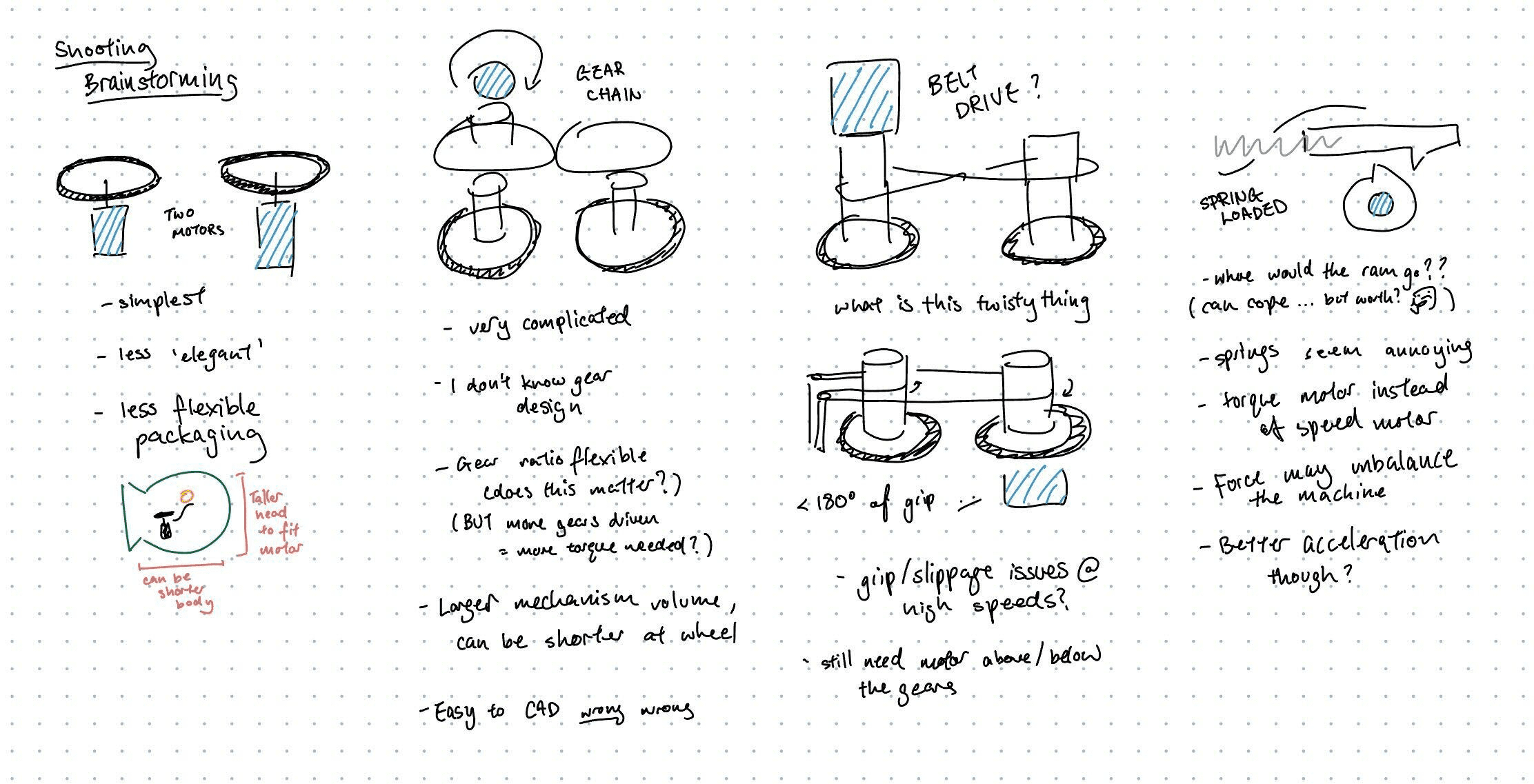
Where the summary is that:
Turns out I still couldn’t decide. I’ve always had trouble thinking of things in the abstract, so the next step was to prototype something.
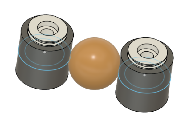
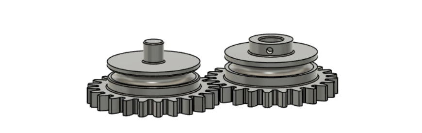
The gears were stiffer and louder than I expected, but worked fairly well. The stiffness could be mitigated by using bearings instead of having a plastic-on-plastic axel, but I was still worried about force transfer and the general loudness/impreciseness of plastic meshing, especially at speeds. With this in mind, I designed the sketched out the following mechanism next:
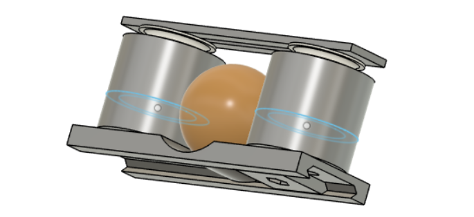
One motor, two gears, two bands.
I redesigned the flywheels to allow for being band-driven, adding a 3mm channel for a rubber band to slot into. Since the wheels are tall and I was worried about bearing loading, each wheel has a press-fit divot for a bearing at the top and bottom (16mm in diameter + theorised 0.05mm offset for snap fit tolerance).
Bearings slot in perfectly. I also designed a slot system to hold the wheels while I’m testing them, allowing me to adjust the spacing between the wheels. Worried about applying tension (from my bands) on a skinny (5mm diameter) 3D print axel, I designed for the central axel to be 55mm long M5 bolt Anthony helped me find in the EECS storeroom. My stackup was to be as follows:
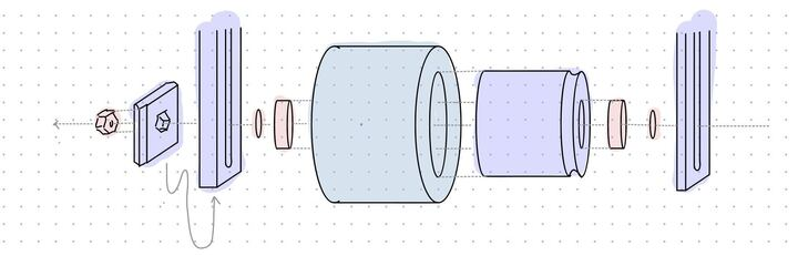
nut-slider-slide-washer-bearing-tire-core-bearing-washer-slider-bolt
Where washers would hold the bearing off of the flat plastic sliders and allow the bearings to turn.
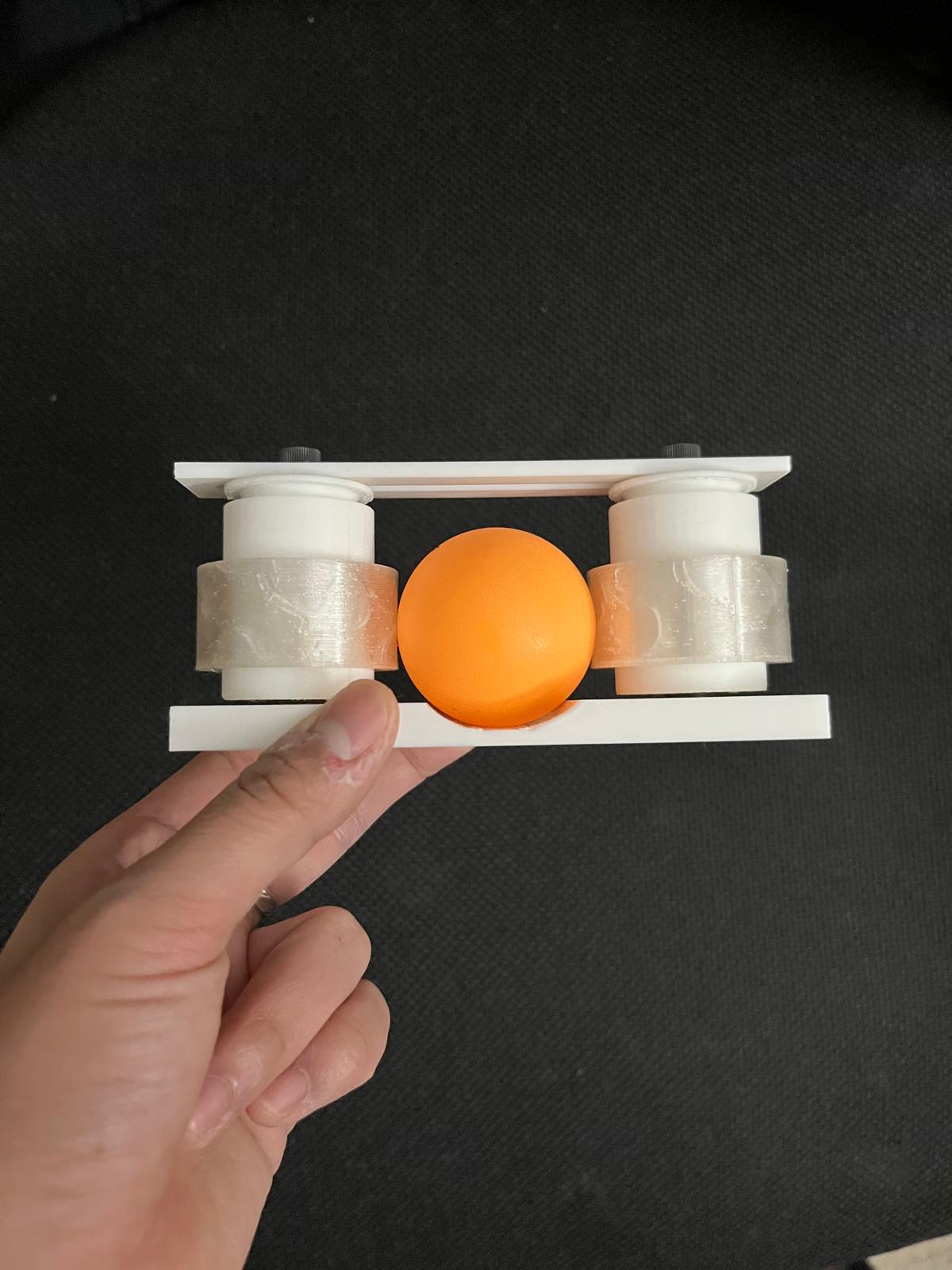
And here is my first draft. I printed the wheel core and top and bottom pieces with PLA at 15% infill on the Prusa Core One, and the tires with TPU at 15% infill (at half height for faster printing). The core was printed with organic supports from the base only to support the band slot and the bearing inset on the bottom of the core.
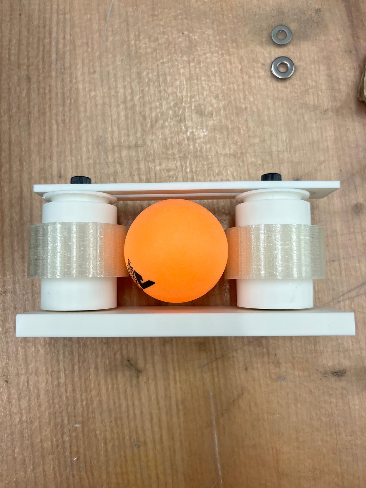
Unfortunately, I had neglected to consider height too much, and while it held together (see above) with one washer on either side, it turns out the roughness from the 3D print necessitated two washers on the bottom of the stackup for smooth spinning, which was just enough that the nut at the bottom could not properly thread onto the bolt. Another issue was that the TPU tire, which kind of worked but wasn’t squishy enough to satisfy me.
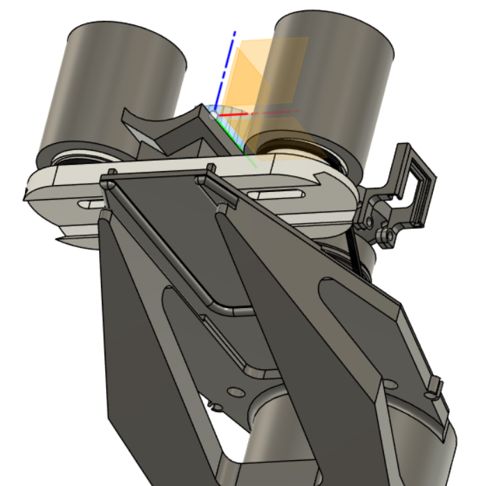
I CADded a shorter stackup and reprinted everything. The TPU tire I reprinted at 5% gyroid infill, which Google told me was a fairly squishy infill option. Here is my final CAD:
And the final test assembly:
I unfortunately only had 4 of the 16mm bearings, but I found a bunch more 22mm-OD bearings in the EDS storeroom, and decided to design to these instead.
Unfortunately, as the gears have to meet above the channel where the ping-pong ball goes (due to the dimensions of the head), the packaging was… not ideal. This is especially exacerbated by the fact that the motor gear (and its motor) has to be completely clear of the ball channel, which would force me to either put the axel of the driven gear above the ball channel and severely limit my support options, or make the gears extra large in diameter, which seemed like an even worse idea with fast motors and plastic gears (something something torque?).
I could go out and find longer bolts for my flywheel axel so that I could raise the entire gear/band mechanism further above the channel, but that also seemed un-ideal, especially since all of this was going to determine head size.
After some deliberation, I realized that this would genuinely all work better upside down, where, if I let the ball drop from a bit of a slope, I’d have significantly more vertical space to work with for my gears.

As I was contemplating this, my PETG gears finished printing. I chose 4 perimeter walls for extra stiffness, and organic supports.
They suck. The rubber band gets caught in the gear teeth, the channel in the middle didn’t get enough support and was scraggly and too narrow to clear, and the 0.05mm clearance that left a beautiful snap fit for the bearing in the PLA did not work nearly so well on the PETG.
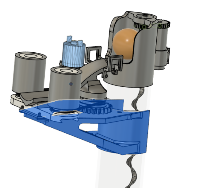
This needed a redesign where the channel was significantly further away from the gears.
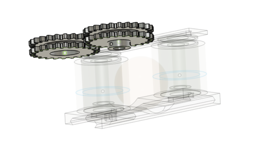
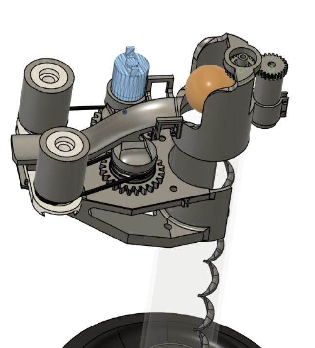
Here, the motor gear would be attached to the motor via set screws, and the driven gear would be attached to the structures via a bearing on top and a bearing on the bottom.
I hold the gears and the motor in place with the slide, which slides (ha) into the base holding the wheels with a pair of dovetial grooves, as this would allow for easy adjustability in the y-direction to adjust tension in my bands, without needing to reprint my entire slide.
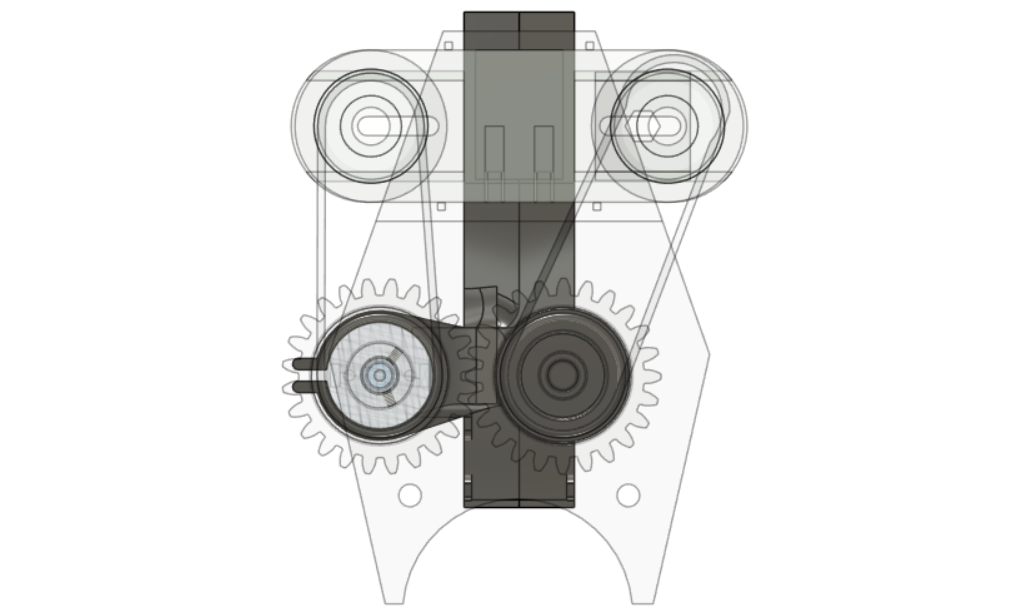
Unfortunately, because of the flip upside down and the addition of the slide, it no longer seemed possible to use the 55mm bolts as an axel through both wheels. Instead, I used a singificantly shorter bolt to hold the bottom bearing to the sliding base.
// insert image
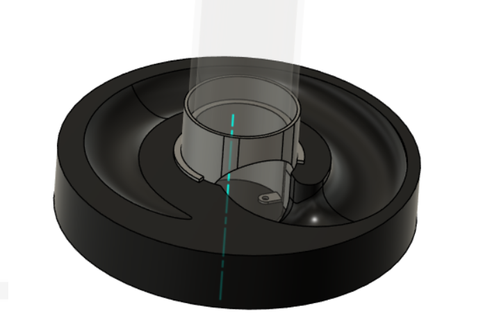
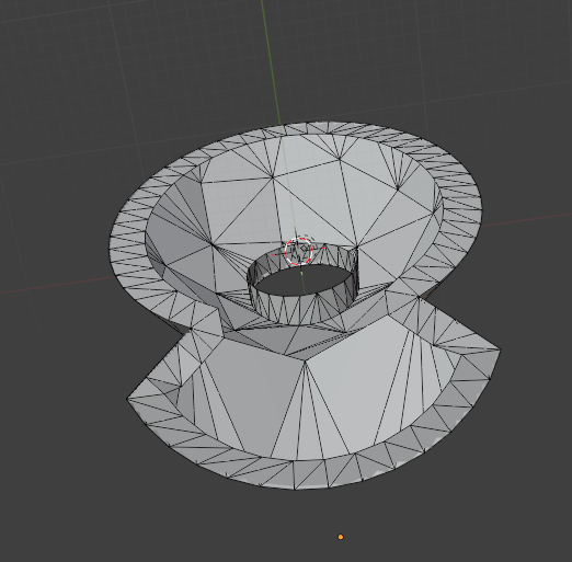
I created a little test spiral and base emulating what the bottommost section of my feed mechanism was going to be.
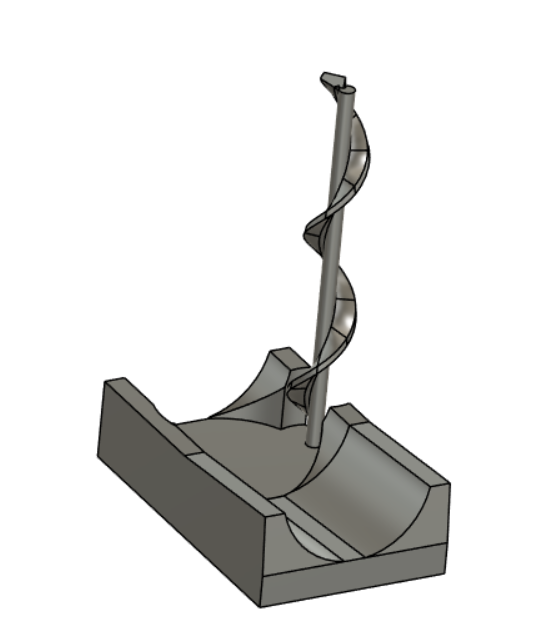
I only really printed a couple of these small spirals before I found one I was happy with. I decied on final parameters of 40mm pitch, 0.2mm spiral rib thickness, 4mm spiral ID, and 15mm spiral OD.
My input devices week implements and tests a distance-sensing system.
My output devices week links these sensors to my chosen motors.
At this point, my documentation becomes super patchy, and everything sort of happened in parallel all at once in the week immediately preceeding the final project presentation. These will be grouped by section and not strictly chronological.
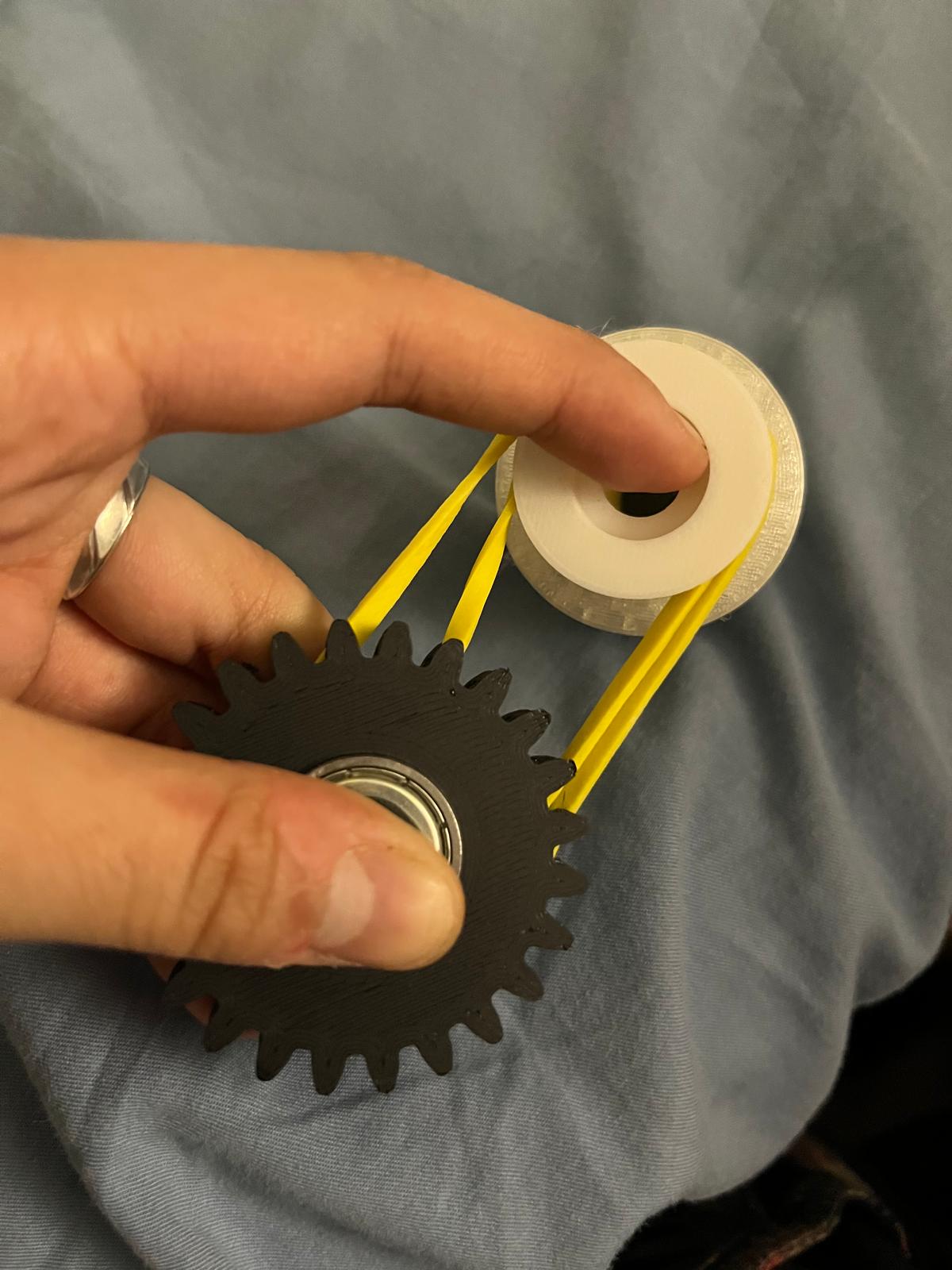
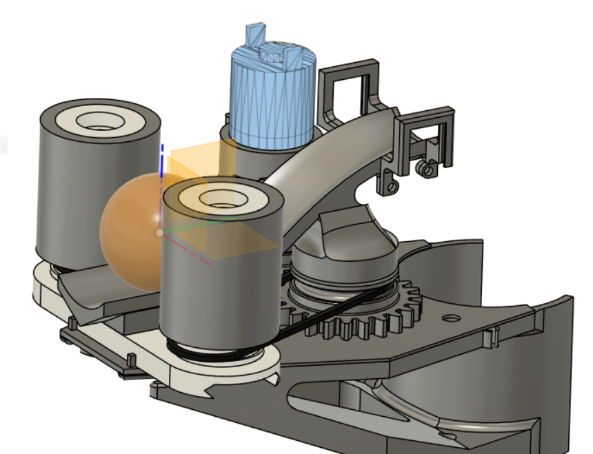
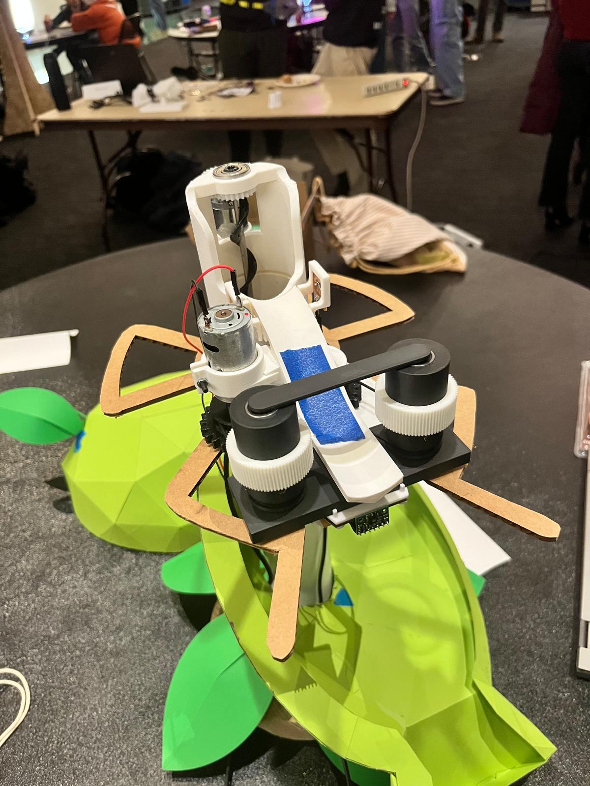
I printed a floor to constrain the entire mechanism better, and tested spinning with a power supply and some rubber bands to act as my belt. This rubber band was just generally annoying - it slipped out of its groove relatively often, and, since it was long enough that it had to be folded in on itself, it wasn’t as effective at force transfer.
I ended up replacing them with 2 3/8” o-rings bought from McMaster. These ended up still having some slack in them, but they transferred force adequately. I ended up also increasing the distance between the gears and the wheels on the floor - which was perfectly doable (for test purposes) in the 30 minutes it takes to print the floor because of the dovetail groove attachment between the ball slide (attached to gears) and the wheel holder (attached to wheels). To improve grip, I also printed a new batch of TPU gears with ridges on them (max diameter 40mm, 1 perimeter, infill 10% gyroid), which turned out much squishier, I think partially also because of change of filament.
This started shooting actually pretty smoothly:
The base I CNC-milled, as I had planned to do. I found a piece of wood measuring about 20x20x40cm and shrunk my previous CAD from week 1 down to fit within these dimensions. I then, with help from the wonderful Anthony, constructed a CAM program to 3-axis mill the wood on the EDS router.
There were 3 parts:
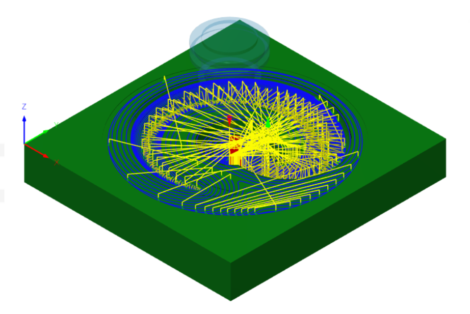
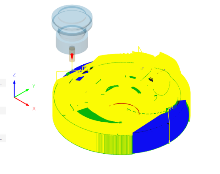
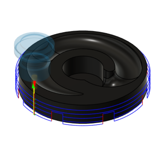
We then created a program for the Avid CNC and did some very similar setup to Make Something Big week to set up and zero the machine. The block of wood we screwed into the sacrificial surface of the machine with brass screws.
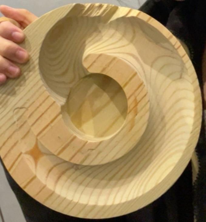
Result:
For the main tube of the peashooter, I purchased a length of 2.067” ID PVC pipe, as I didn’t really see the point in manufacturing for myself a tube. I cut it to length on a bandsaw and used a manual mill (to be fair, more like fancy drill press) to mill a slot down its side, as someone suggested it’d be cool to watch the ping pong balls as they went up the stalk.
I then designed and 3D-printed (PLA, default settings, organic supports) the following holder that would press fit both in the floor and against the pipe:
As well as structure that would attach to the PVC pipe and support the shooting mechanism floor. It was great that this and the floor were separate pieces, as this was a 4-hour print and I was glad that it did not need to be reprinted with minor changes in the floor.
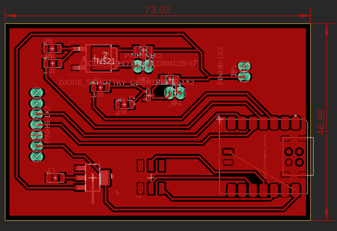
It also contained an 50x80mm slot for a PCB right under where the shooting mechanism would go, to minimize wire lengths.
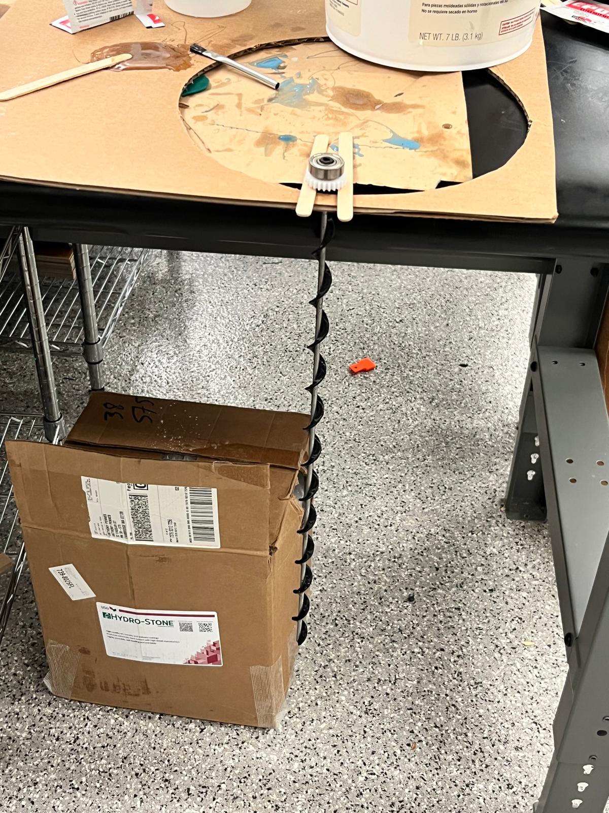
The original plan was to 3D-print the spiral as I’d printed it for the test piece. To maximise stiffness, I printed it at 4 perimeters in PETG. Unfortunately, it was still wayyy too flexy, and the motor could not successfully transfer torque the full way through to transmit balls up.
I then attempted a few more ideas, including:
I went on a mini quest until I found a length of 4mm diameter steel rod scrap, which actually seemed perfect. I then printed the same structure without the plastic core, wrapped it around the metal core, and used epoxy to bond the two. This was significantly stiffer and worked significantly better.
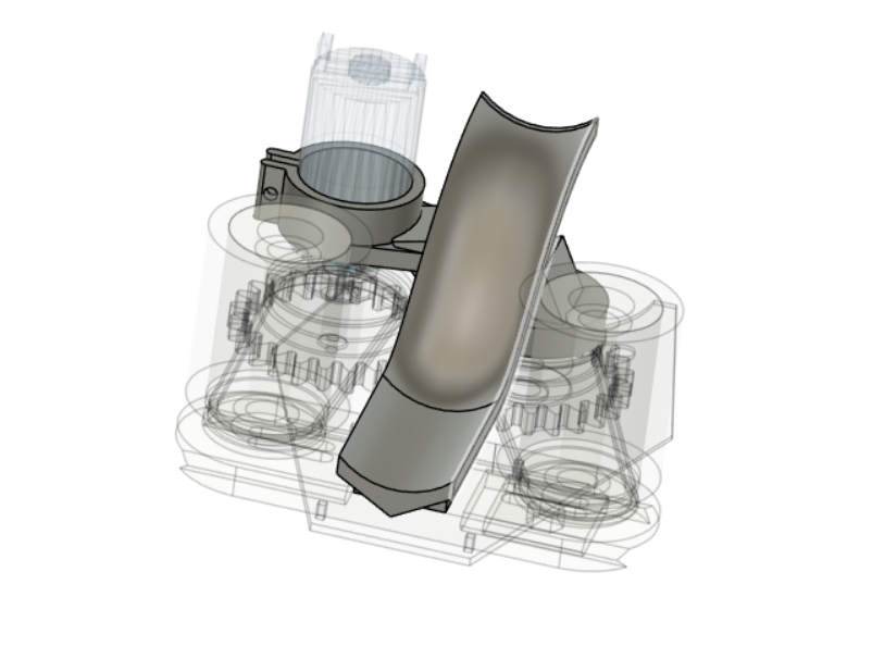
I then also created a pipe cuff to hold the motor and a bearing that constrained the top of the spiral.
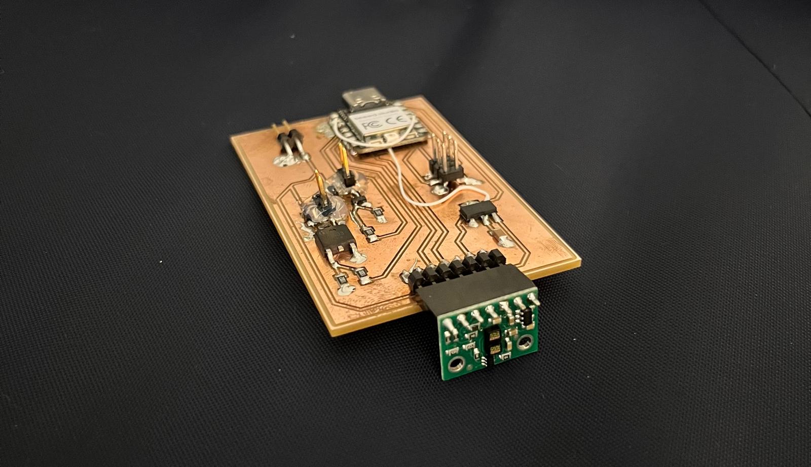
I initially used the PCB made during input/output devices week to test my motors, but the transistor on the shooting motor blew when I attempted to put a little more current on it. Makes sense - it was only rated for 3A. I replaced it with a larger transistor and reshaped my board to be less than 5cm by 8cm.
Then I soldered the whole thing and slotted it into the slot I made on the shooting support. I used hot glue to reinforce the motor pins (where I had lost traces previously), and had to wire two pins on the XIAO together, as I’d accidentally put my analog sensor on a non-analog pin.
I then re-printed the slide with the final design, including little holders for the beam-break sensor.
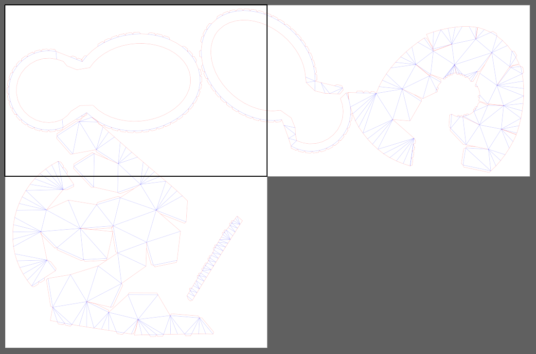
I wanted the exterior to be quick to manufacture, despite its volume, and so was thinking of ways to lasercut. In a stroke of inspiration, I found this Blender extension called Export Paper Model that allowed you to export meshes as nets. This was perfect.
In Fusion, I then sketched out the shapes I wanted (including making sure that all areas that I didn’t want were distinct from ones I did, e.g. by pushing in the hole for the peashooter mouth), converted it to a mesh, and reduced the face count until it was suitably low poly.
I then loaded this into Blender. In here, I deleted the faces I did not want, converting these closed objects into open surfaces.
Then I exported as an SVG and did some recoloring/arranging on Adobe illustrator.
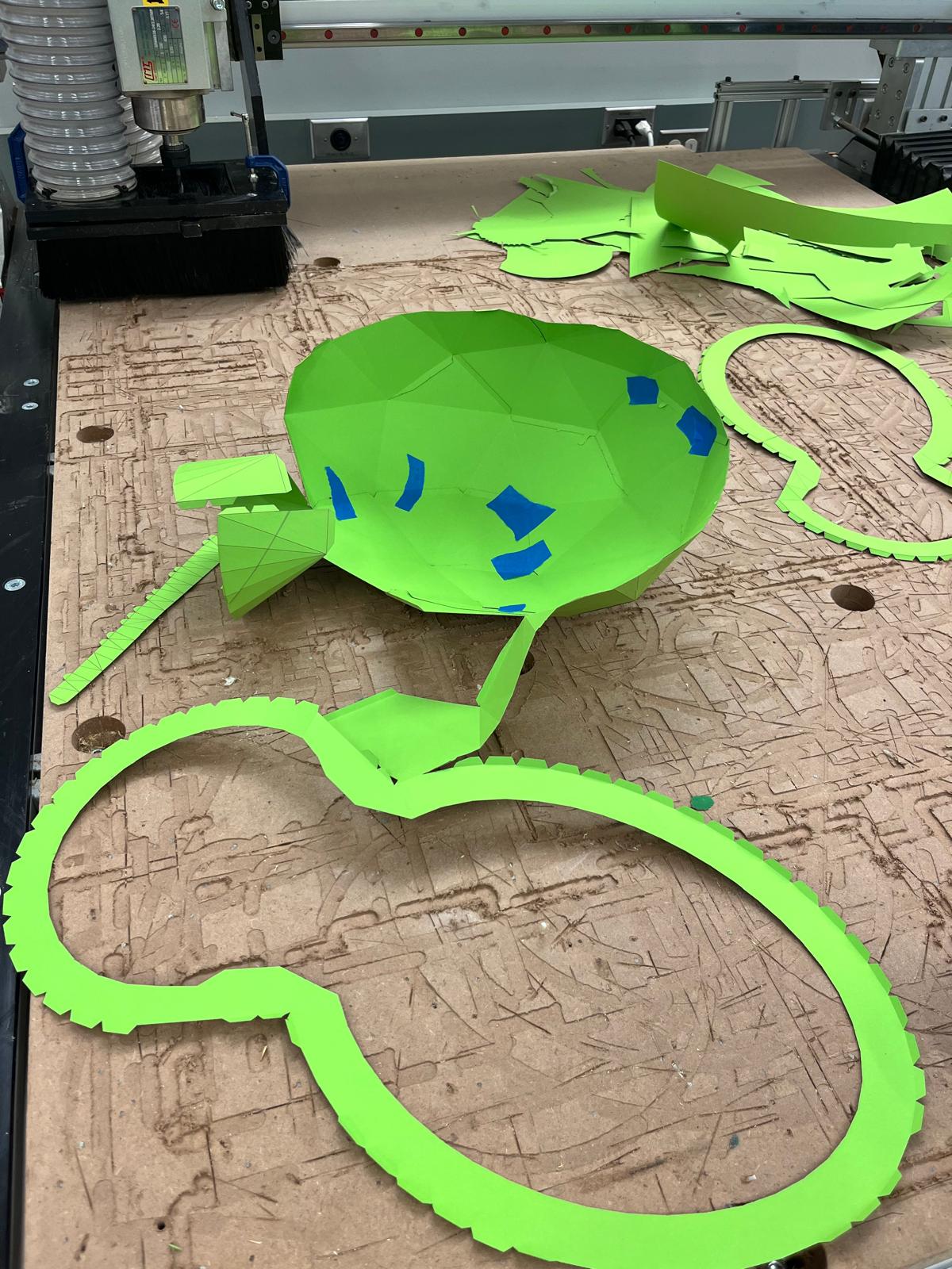
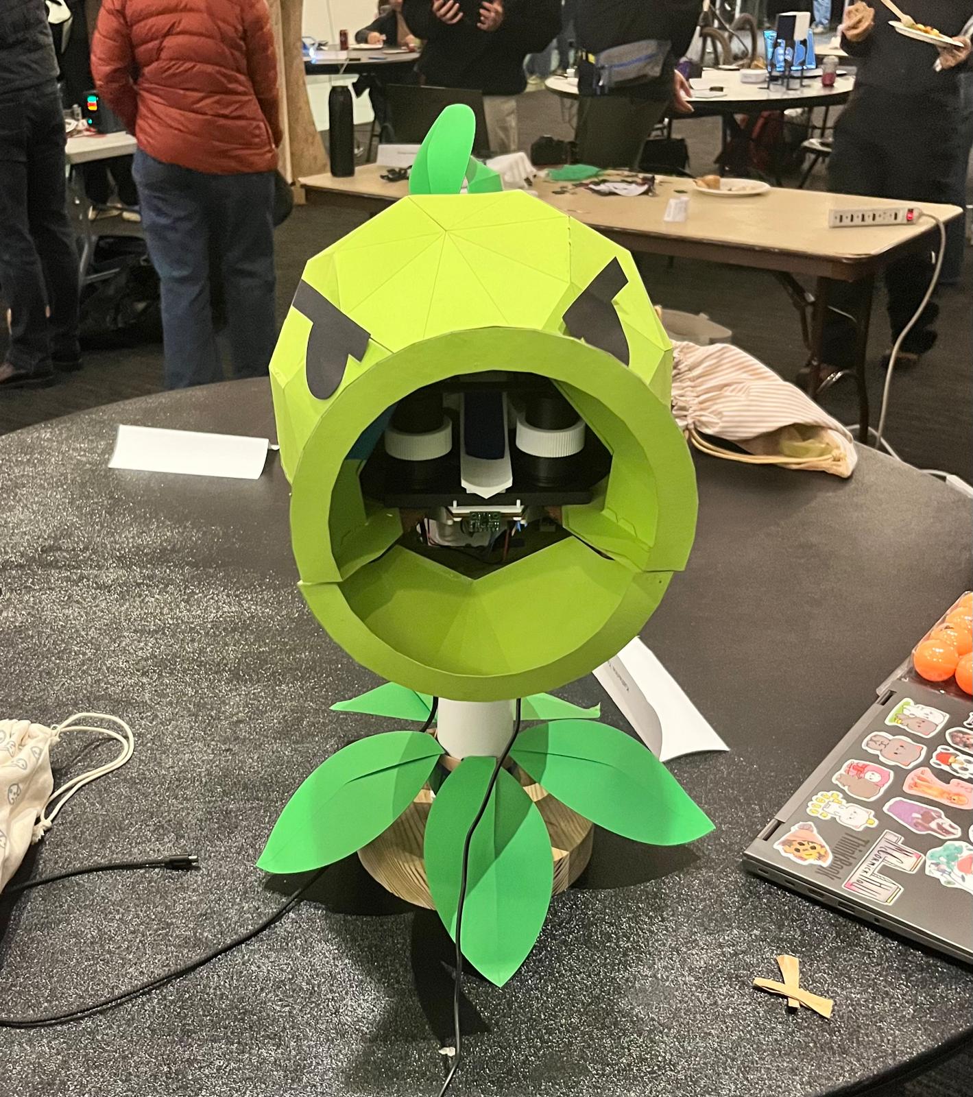
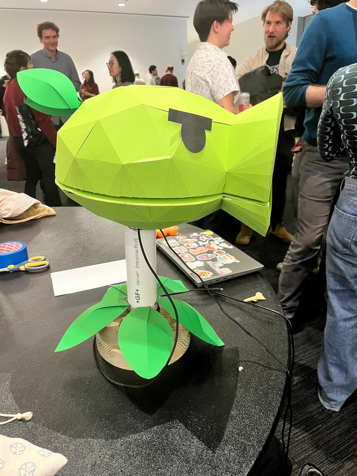
On a scrap sample of cardstock, I tested lasercutter settings until I found working settings: cut speed 100% power 60%, engrave speed 100% power 25% . I then cut my actual pieces and assembled them.
I then lasercut this cardboard support that gets sandwiched between the shooting support and the shooting floor.
And lasercut some and eyes to finish it off!
/*
This example shows how to take simple range measurements with the VL53L1X. The
range readings are in units of mm.
*/

#include <Wire.h>
#include <VL53L1X.h>

#define RED 17
#define GREEN 16
#define BLUE 25

#define MOTORA 29
#define MOTORB 28

#define IRLED 3
#define PHOTOTRANSISTOR 27

const int THRESHOLD = 50;
const int SPIN_TIME = 800;

const bool serial = true;

VL53L1X sensor;

int ambient;
int trigger_time;
int last_beam;

int on_measurements[3] = {0, 0, 0};
int off_measurements[3] = {0, 0, 0};
int idx = 0;

int photoread() {
  digitalWrite(IRLED, HIGH);
  delay(30);
  on_measurements[idx] = analogRead(PHOTOTRANSISTOR);
  // if(serial) { Serial.println(on); }

  digitalWrite(IRLED, LOW);
  delay(10);
  off_measurements[idx] = analogRead(PHOTOTRANSISTOR);
  // if(serial) { Serial.println(off); }

  idx += 1; idx %= 3;

  int on = (on_measurements[0] + on_measurements[1] + on_measurements[2]) / 3;
  int off = (off_measurements[0] + off_measurements[1] + off_measurements[2]) / 3;

  return abs(on - off);
}

void setup()
{
  pinMode(RED, OUTPUT); digitalWrite(RED, HIGH);
  pinMode(GREEN, OUTPUT); digitalWrite(GREEN, HIGH);
  pinMode(BLUE, OUTPUT); digitalWrite(BLUE, HIGH);

  pinMode(MOTORA, OUTPUT);
  pinMode(MOTORB, OUTPUT);

  pinMode(IRLED, OUTPUT); digitalWrite(IRLED, HIGH);
  pinMode(PHOTOTRANSISTOR, INPUT);
  pinMode(4, INPUT);


  photoread(); photoread(); // fill up buffer;
  ambient = photoread();

  if (serial) {
    Serial.begin(115200);
    Serial.println("Begin");
    Serial.println(ambient);
  }

  Wire.begin();
  Wire.setClock(400000); // use 400 kHz I2C

  sensor.setTimeout(500);
  if (!sensor.init())
  {
    // Serial.println("Failed to detect and initialize sensor!");
    digitalWrite(RED, LOW);
    while (1);
  }

  sensor.setDistanceMode(VL53L1X::Long);
  sensor.setMeasurementTimingBudget(15000);
  sensor.startContinuous(15);
  // Serial.println("new program");

  trigger_time = millis() - SPIN_TIME;

}

void loop()
{
  int current_time = millis();

  // inputs

  int beam = photoread();
  int dist = sensor.read();

  if (serial) {
    Serial.println(beam);
  }

  if (beam > ambient + THRESHOLD || beam < ambient - THRESHOLD) {
    digitalWrite(BLUE, LOW);
    trigger_time = millis();
  }
  else {
    digitalWrite(BLUE, HIGH);
  }

  if (dist < 1000) {
    digitalWrite(GREEN, LOW);
    digitalWrite(MOTORB, HIGH);
  }
  else {
    digitalWrite(GREEN, HIGH);
    digitalWrite(MOTORB, LOW);
  }

  if (current_time < trigger_time + SPIN_TIME) {
    // digitalWrite(MOTORA, HIGH);
    digitalWrite(RED, LOW);
  }
  else {
    digitalWrite(MOTORA, LOW);
    digitalWrite(RED, HIGH);
  }

}In the early morning hours on the day of the presentation, it finally worked:
… Unfortunately, my PCB failed just before my actual presentation, so these are the videos I have. I believe that one of the already-damaged traces leading to the high-current motor finally, actually failed. Should definitely have made that trace thicker.
This was super fun, especially figuring out what manufacturing method was best suited for each of my components. This was also incredibly challenging, and definitely pushed my design and making skills. Thanks, everyone, for the amazing class!
Files: PCB design, CAD