HTMAA 25
home about me final projectThis week’s task was to create a microcontroller board with an input device. As will be seen, I largely took this as an opportunity to create a first version of the electronics I will need for my final project.
Using an oscilloscope, we measured the signals produced by a microphone as well as a phototransistor. See full documentation.
I wanted to use the input devices and output devices weeks to essentially create a first draft of the entire electronics of my final project - the peashooter. This meant that at minimum it should incorporate:
After consulting with Anthony, I was handed the VL53L1X Time-of-Flight Distance Sensor, the JYCRS390H 12V DC Motor, and the PZ22GR9120R DC Gearmotor.
The 12V motors also meant that I needed a 12V power supply to the board separate from the 5V USB line from my laptop.
Additionally, I wanted to include the following:
My first general sketch looked something like:
// insert picture
Again another consultation with Anthony and some online sources, I made the following refinements:
This resulted in the following sketch:
// insert picture
And the following Fusion schematic:
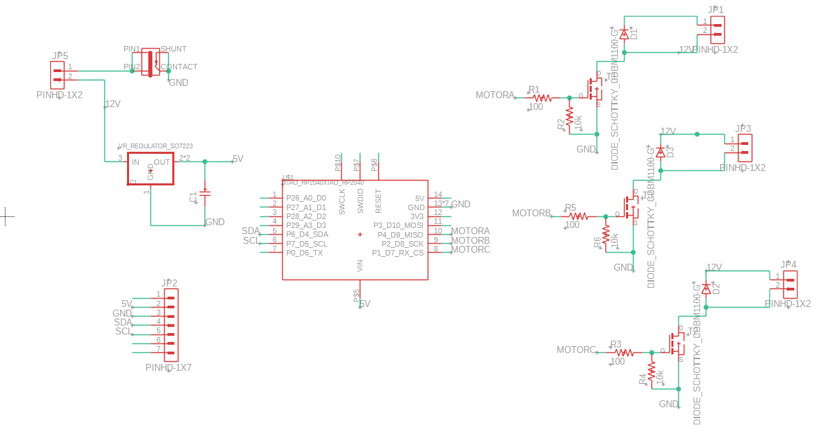
In the course of drawing the schematic, I also made the following choices:
My first PCB layout was the following:
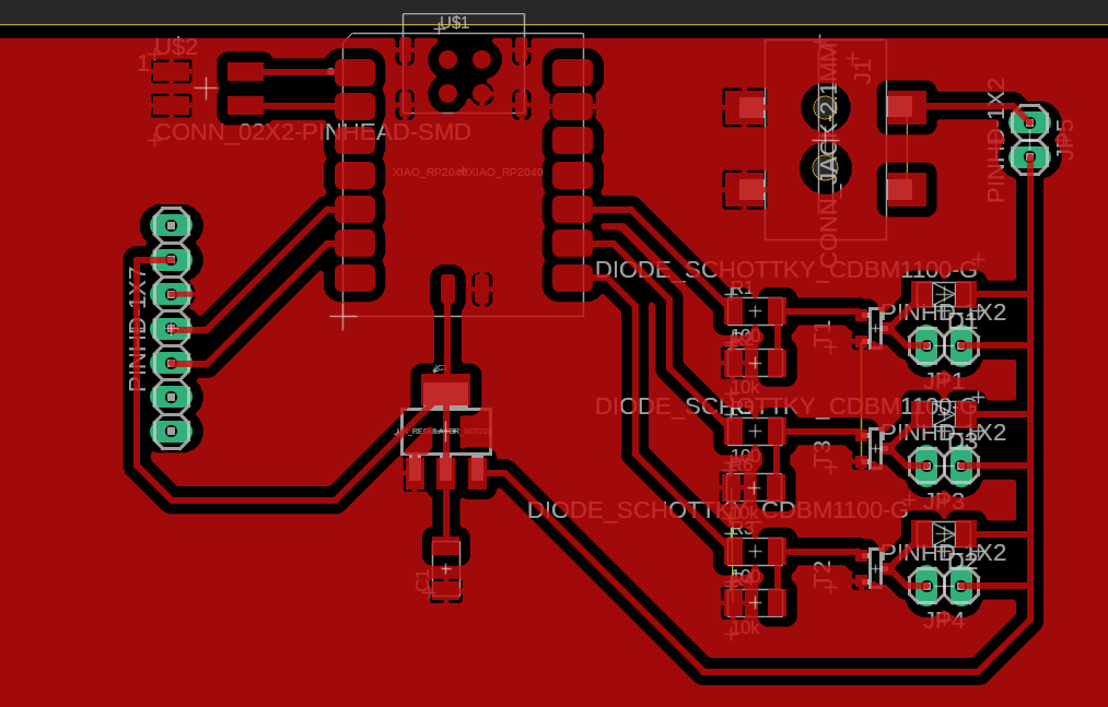
Which seemed neat and well laid-out, until I realized that ground was not connected. Most importantly, the source of two of my transistors did not contact ground. Since the motor current would be going through those points, I didn’t want to just put on a 0-ohm resistor.
In retrospect, this may have been an unnecessary design rule I imposed on myself, as consulting a data sheet for a 0-ohm 1206 resistor would have told me that many of them are definitely rated for enough current. Oh well.
After trying out a few other board layouts, e.g. the following (where I also updated the barrel jack to a component that we actually had)
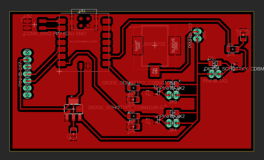
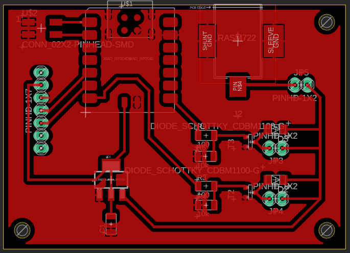
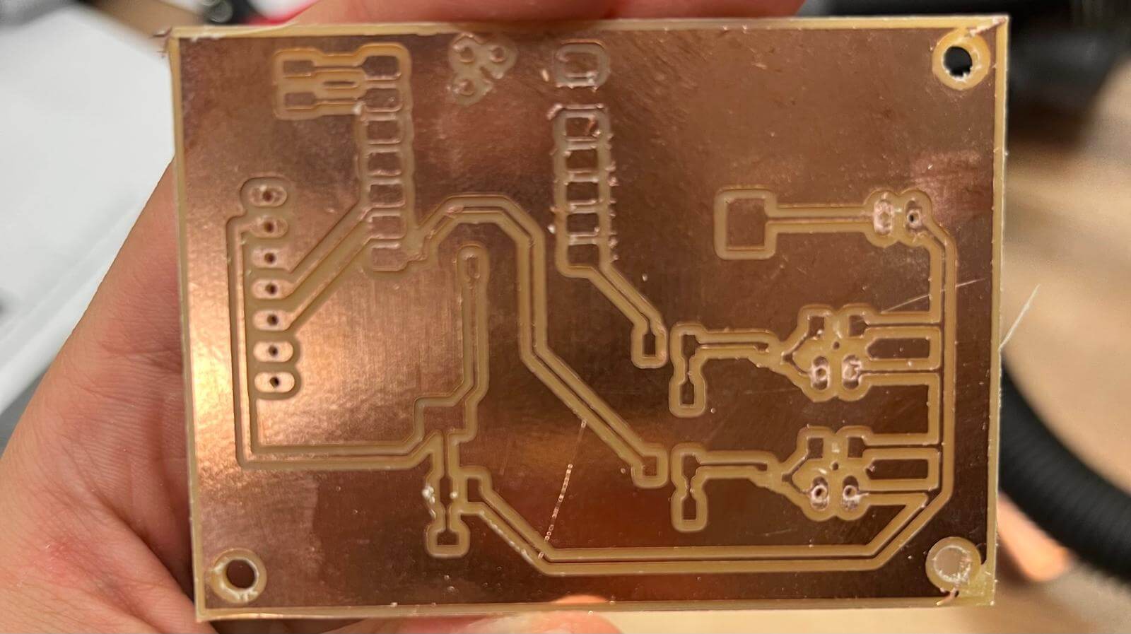
Note, however, that ground ground is still not connected on one of my motors. I decided that laying out three motors nicely would be topologically impossible with a single-layer PCB and decided to abandon the extra motor. This led to the final layout of:
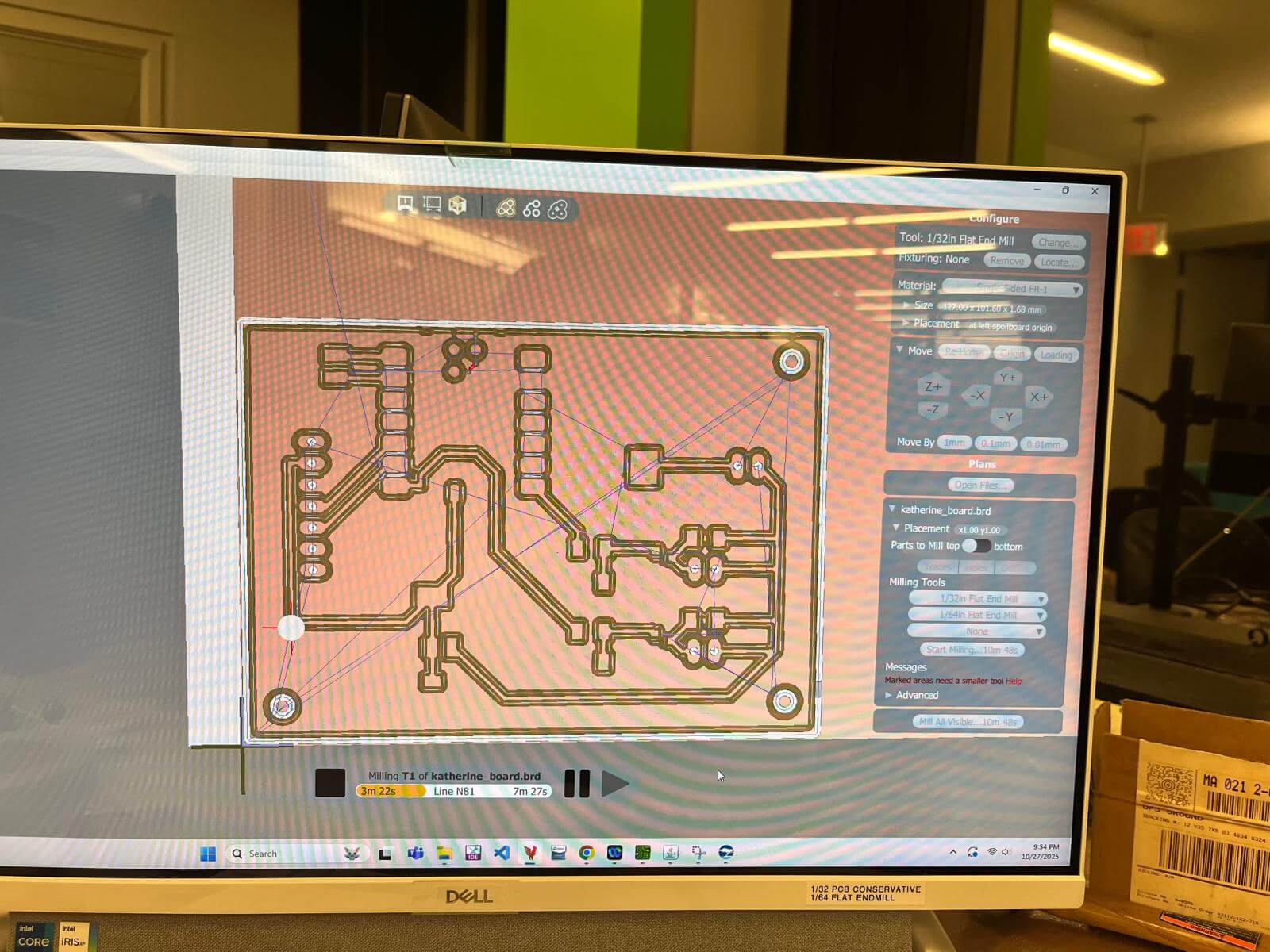
Using the Bantam Tools Othermill, the PCB was cut from single-sided FR1. The total milling time was about 10 minutes.
Since I was using the pads under the microcontroller that I could not access with a traditional soldering iron, I knew I needed to reflow solder the microcontroller. Unfortunately, after trying and failing to do this for a decent amount of time, I was running behind my self-imposed schedule and, for supply-side time management purposes, decided to go for a much less elegant method of simply sticking wires where they needed to go.
A thin wire was soldered to the Vin pad at the back of the microcontroller, then the entire back was covered with kapton tape and the microcontroller was traditionally soldered to the relevant pads. Since the back was no longer entirely flat, extra care was taken on this step.
The wire sticking out from underneath the back was then soldered to the original Vin trace. Instead of repeating the same thing for the ground pad from under the microcontroller, I wired ground over from an adjacent area on my ground pour.
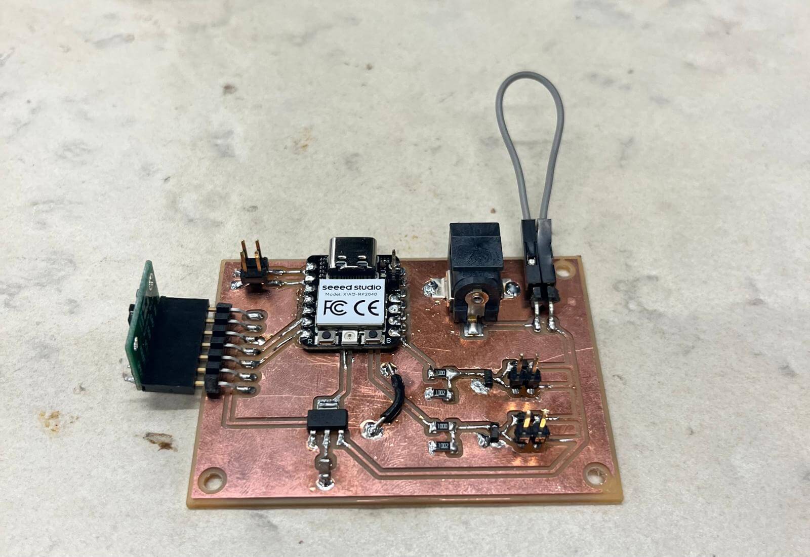
The rest of the components went on uneventfully. Here is the final result:
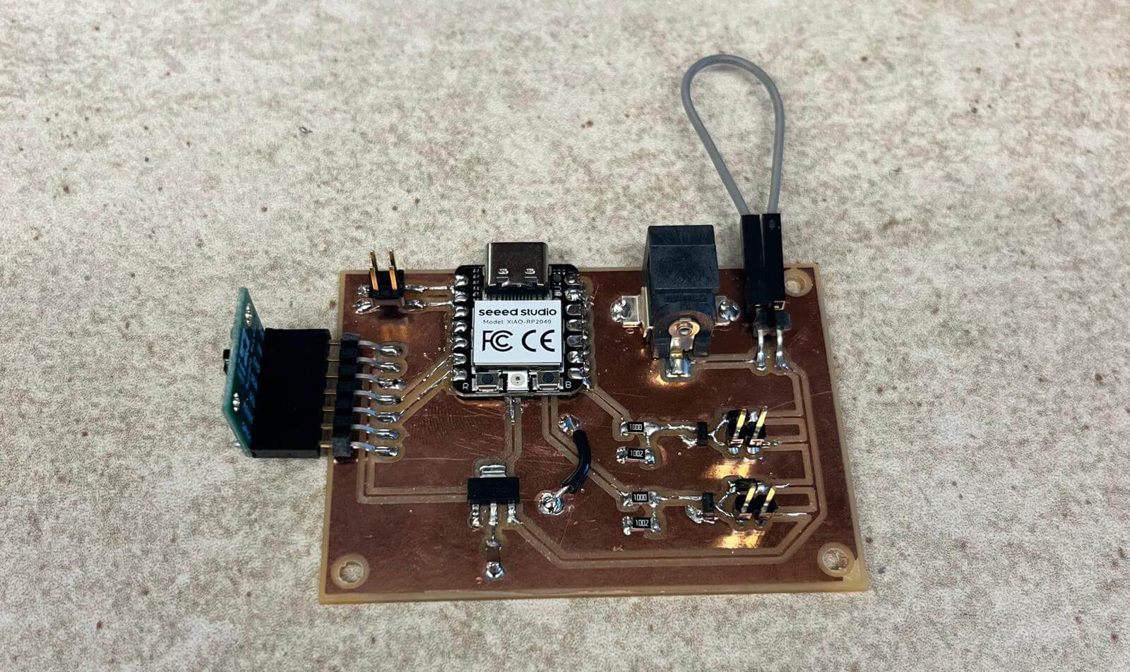
I used a small jumper wire to bidge the gap I left in my circuit for the switch.
To test the Time of Flight sensor, I first borrowed the default code provided by pololu to get serial readings of distance.
#include <Wire.h>
#include <VL53L1X.h>

VL53L1X sensor;

void setup()
{
  while (!Serial) {}
  Serial.begin(115200);
  Wire.begin();
  Wire.setClock(400000); // use 400 kHz I2C

  sensor.setTimeout(500);
  if (!sensor.init())
  {
    Serial.println("Failed to detect and initialize sensor!");
    while (1);
  }

  sensor.setDistanceMode(VL53L1X::Long);
  sensor.setMeasurementTimingBudget(50000);

  sensor.startContinuous(50);
}

void loop()
{
  Serial.print(sensor.read());
  if (sensor.timeoutOccurred()) { Serial.print(" TIMEOUT"); }

  Serial.println();
}Since this worked pretty smoothly, I then modified the code so that it would work without Serial, in anticipation of later powering my board off of the 12V barrel jack. This script turns on the blue LED on the XIAO if something is detected within 300mm.
#include <Wire.h>
#include <VL53L1X.h>

#define RED 17
#define GREEN 16
#define BLUE 25 // from XIAO RP2040

VL53L1X sensor;

void setup()
{
  pinMode(RED, OUTPUT); digitalWrite(RED, HIGH);
  pinMode(GREEN, OUTPUT); digitalWrite(GREEN, HIGH);
  pinMode(BLUE, OUTPUT); digitalWrite(BLUE, HIGH); // high = off

  Wire.begin();
  Wire.setClock(400000); // use 400 kHz I2C

  sensor.setTimeout(500);
  if (!sensor.init())
  {
    digitalWrite(RED, LOW);
    while (1);
  }

  sensor.setDistanceMode(VL53L1X::Long);
  sensor.setMeasurementTimingBudget(15000);
  sensor.startContinuous(15);
}

void loop()
{
  int dist = sensor.read();

  if (dist < 300) {
    digitalWrite(BLUE, LOW); // on
  } else {
    digitalWrite(BLUE, HIGH); // off
  }
}
Plugging this into 12V, we see our 12V power works as well!
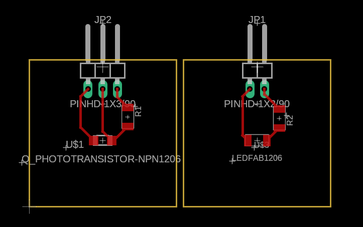
I designed 1” by 1” boards to hold the phototransistor and LED circuit components. As I did this, I realized that my phototransistor did in fact need an additional 3.3V pin, which I had neglected to include in my main PCB (this is why I should not have waited to do the phototransistor/led schematics). This will be dealt with in a sketchy fashion momentarily.
I also designed a holders on Fusion 360 that holds the two boards at >40mm apart - or enough pass a ping pong ball through. Since this was done in a hurry, it is slightly oversized.
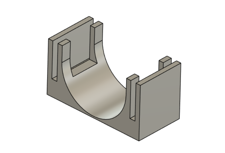
I then printed the holder and milled the parts. As both these machines were running, I soldered a single pin to the 3.3V output on the XIAO.
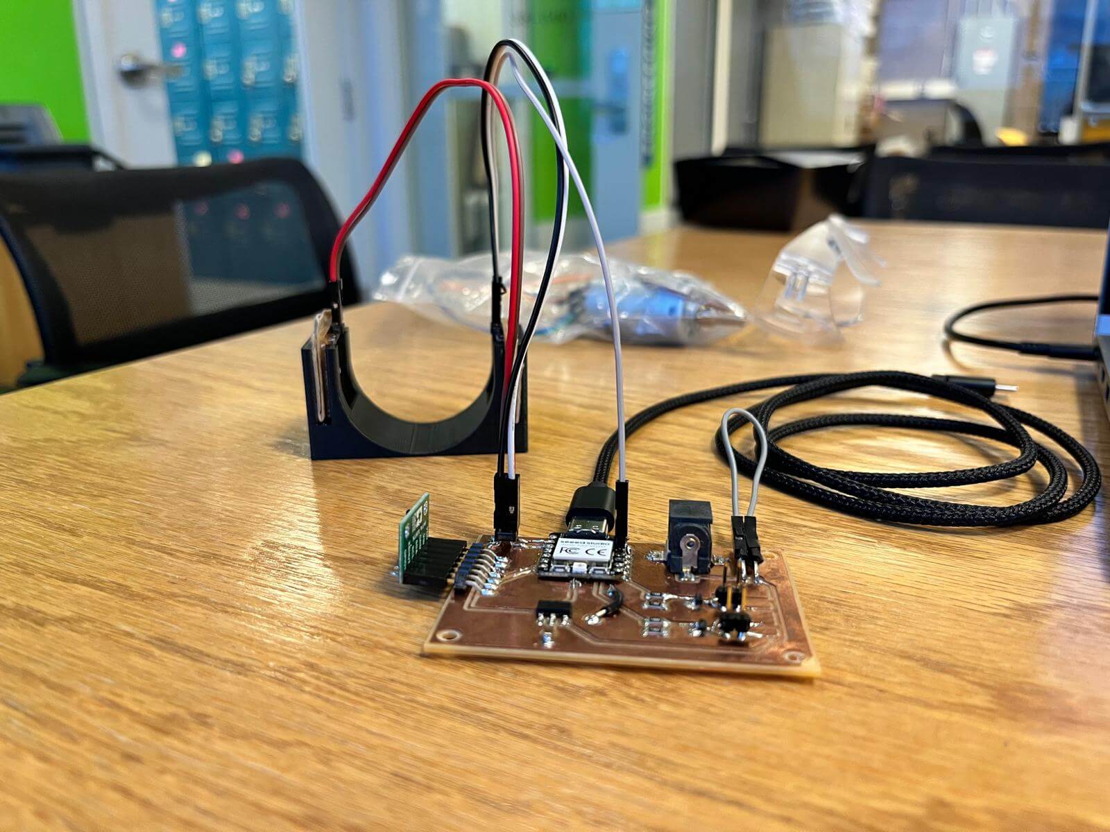
Here is the fully assembled beam-break sensor:
To test this, I ran the following code to get an idea of what my cutoff values would be:
#define IRLED 26
#define PHOTOTRANSISTOR 27

void setup() {
  pinMode(IRLED, OUTPUT);
  pinMode(PHOTOTRANSISTOR, INPUT);

  Serial.begin(9600);
}

void loop() {
  digitalWrite(IRLED, HIGH);
  delay(200);
  Serial.println(analogRead(PHOTOTRANSISTOR));

  digitalWrite(IRLED, LOW);
  delay(200);
  Serial.println(analogRead(PHOTOTRANSISTOR));
}
Unfortunately, with my original circuit (a 10kOhm resistor on the phototransistor and a 100 ohm resistor on diode), there was no difference between having the LED on and off - I got a consistent reading of 11 or 12 every tick.
Some searching revealed that bumping the resistor in series with the phototransistor would improve the sensitivity of these readings, so I increased that resistance to 100kOhm, which still didn’t produce enough difference. While we could see that values with the LED off would be in the low 20s and on would be in the high 20s or low 30s, this was not enough difference that I’d trust a cutoff value I gave to work with any kind of environmental variation.
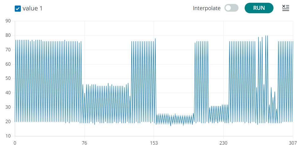
One last bump as I desoldered the resistor once again and soldered in a final 1MOhm resistor. This seemed to make the difference! The on/off distance was beyond random fluctuation error (see graph). Upon testing, I also interestingly discovered that my ping pong ball is slightly translucent in IR:
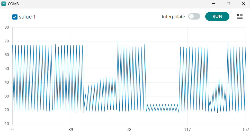
(dips in graph represent ping pong ball, hand, ping pong ball)
I then decided to see if I could push the contrast more by bumping the LED brightness. I reduced LED resistor value to 50Ohm, which is slightly above the resistance needed to produce maximum current. This produced the following graph:
(dips represent ping pong ball, hand, piece of paper, rolling ping pong ball)
… which isn’t really much different from the theoretically half-as-dim LED. Oh well, it was still enough contrast for my purposes. Using a reading of ~60 as my cutoff value, we can now see the sensor detect a ping-pong ball:
This is definitely a draft 1 board, but all the inputs work! Will probably use this to test things for now and then create a board with better layout (and all the correct pins, soldering etc.) for actual final creation.
Plan for next week: Add motors.