HTMAA 25
home about me final projectThis week, we went over 3D scanning and printing techniques
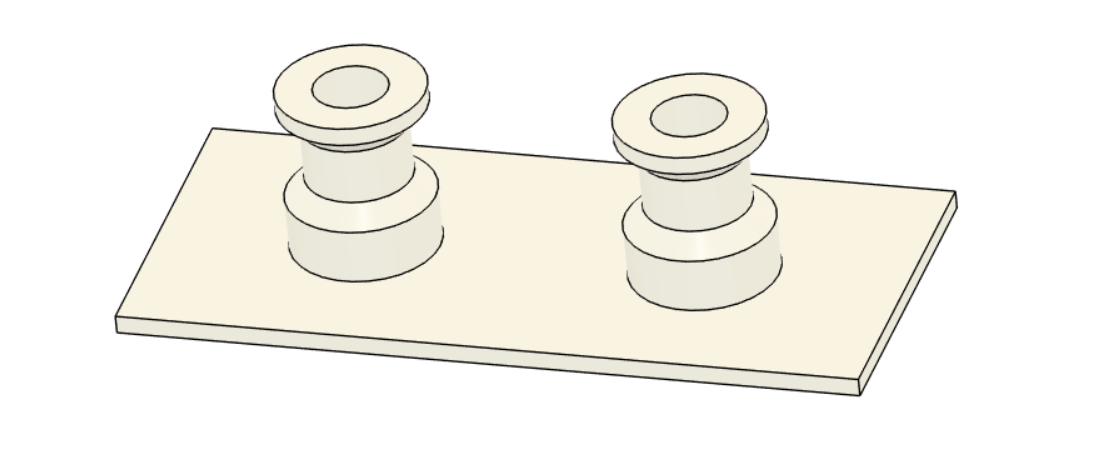
Our first task was to characterize the printer we had in EDS. It is a Prusa CORE One, with a 0.4mm HF nozzle. We printed two beds of design rules, documented here.
For me, the pertinent result was that the ring on the post could move with 0.3mm gap.
I wanted to print something that would be of use to my final project. Within my final project, I have two main mechanisms that may need to be 3D printed - a geared shooting mechanism, and a spiral ball-raising mechanism. The gear mechanism seemed more conceptually sketchy to me, so I decided to design to print a test gear mechanism.
It seemed cool to try and print in place, and would satisfy the assignment of printing something that cannot be subtractively manufactured, so I went with that.
The gears needed to be retained, but with a generous enough clearance gap for movement. While the gears would need to be printed “floating”, with supports, there needed to be no support material in the necessary clearance gaps between the gear and its axel. I decided on this profile:
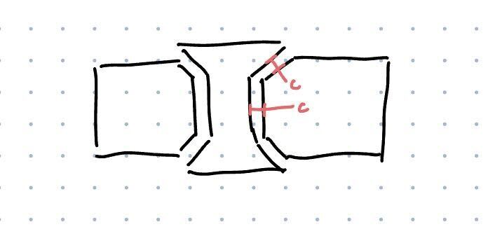
Where 45 degree chamfers, printable without supports, would retain the gear.
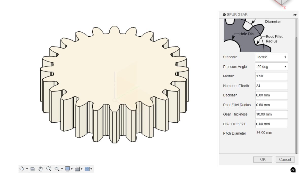
In Fusion, I used to spur gear generation tool to generate the gear, keeping the default settings of a 20 degree contact angle and 24 teeth, but changing the module to 1.5 so that the gear’s meshing diameter (or whatever it’s called) would be 36mm across. I used a root fillet radius of 0.5mm, a gear height of 10mm, and set the hole diameter to 0 - I would be crafting this profile myself.
Next, with the sketch tool, I created the following sketch profile:
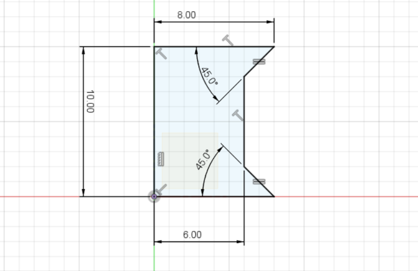
Which I revolved and subtracted from the spur gear body to create the chamfered hole. I then created a linked duplicate of this gear, so that I’d have two.
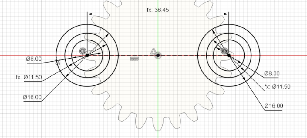
I next created a base plate - an arbitrarily sized rectangle. With a parameter named “clearance”, set initially to 0.3mm, I drew two sets of concentric circles with diameters 8mm, (12mm - 2*clearance), and (16mm - 2*clearance), spaced (36mm + 2 _ clearance) apart. I then extruded them in a spool shape (with the inner cylinder going clearance _ sqrt(2) above and below the gears) and chamfered them with the chamfer tool.
I then used a revolute joint to join the gears to the base, created a reverse motion link between the two joints, and voila!
My first print was the gears with an 0.3mm gap. It worked and spun, but the gears were loose and there was a little much backlash.
I then reduced my clearance parameter to 0.25mm (and also modified the CAD to include the axel-hole and a smaller base, in hopes of saving print time) and reprinted. It turns smoother and quieter!
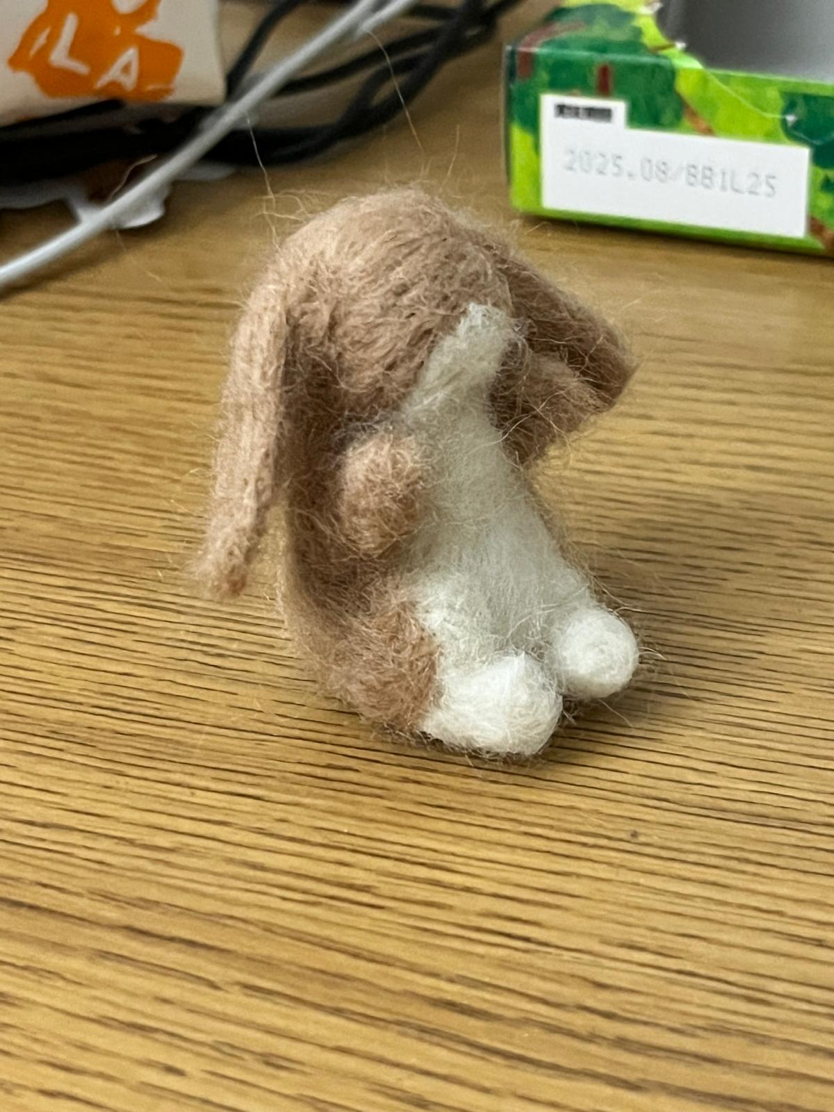
As my object to 3D scan, I chose this little bunny I felted a while ago. It’s asymmetric and light-colored, but has overhangs (under the ears) and lots of fuzz as surface noise. I was curious to see how it scanned.
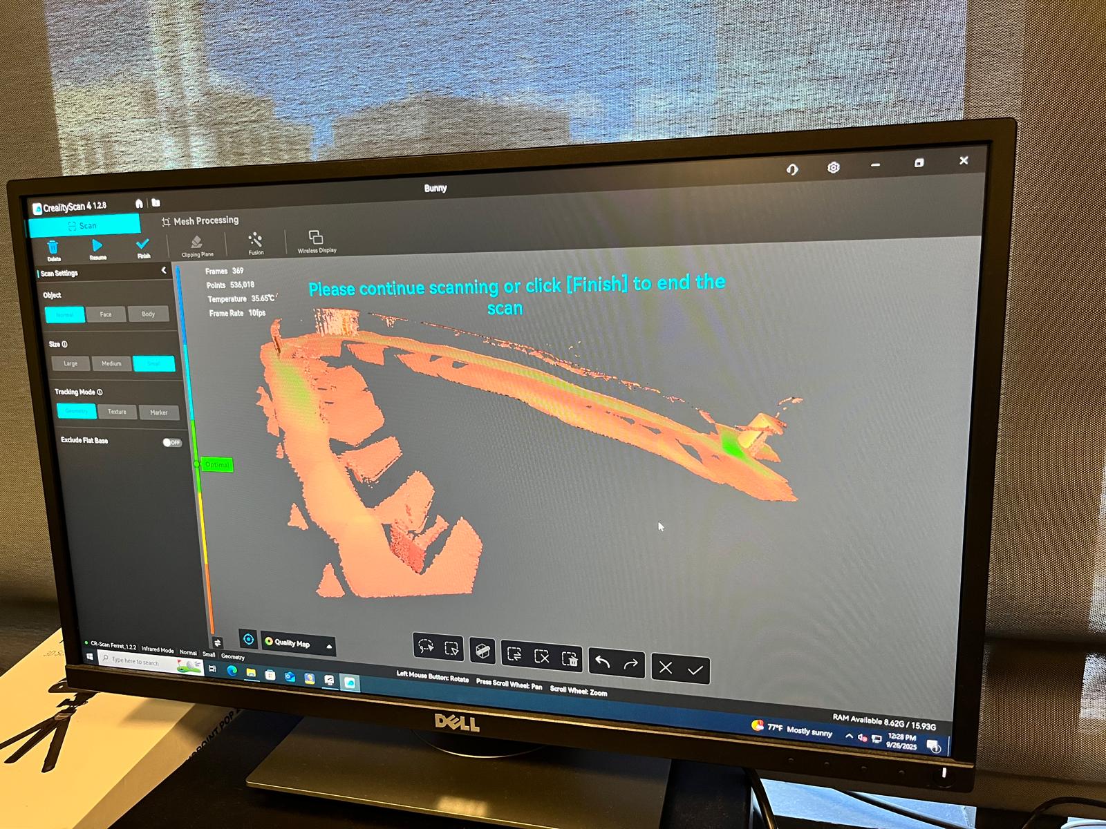
Our scanner was the Creality Ferret Pro. The bunny was placed on a small box atop an automatically-rotating lazy susan. As expected, the first attempt did not go very well, and the software seemed to have difficulty tracking the object.
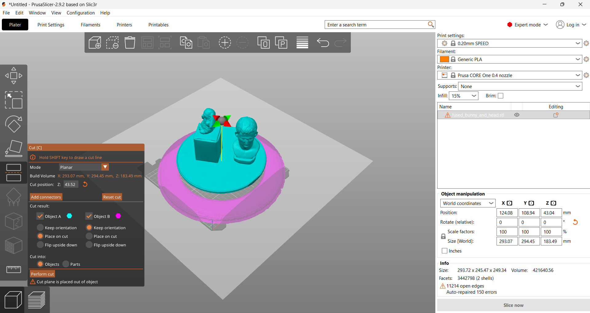
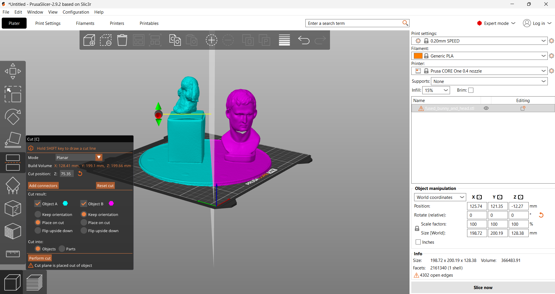
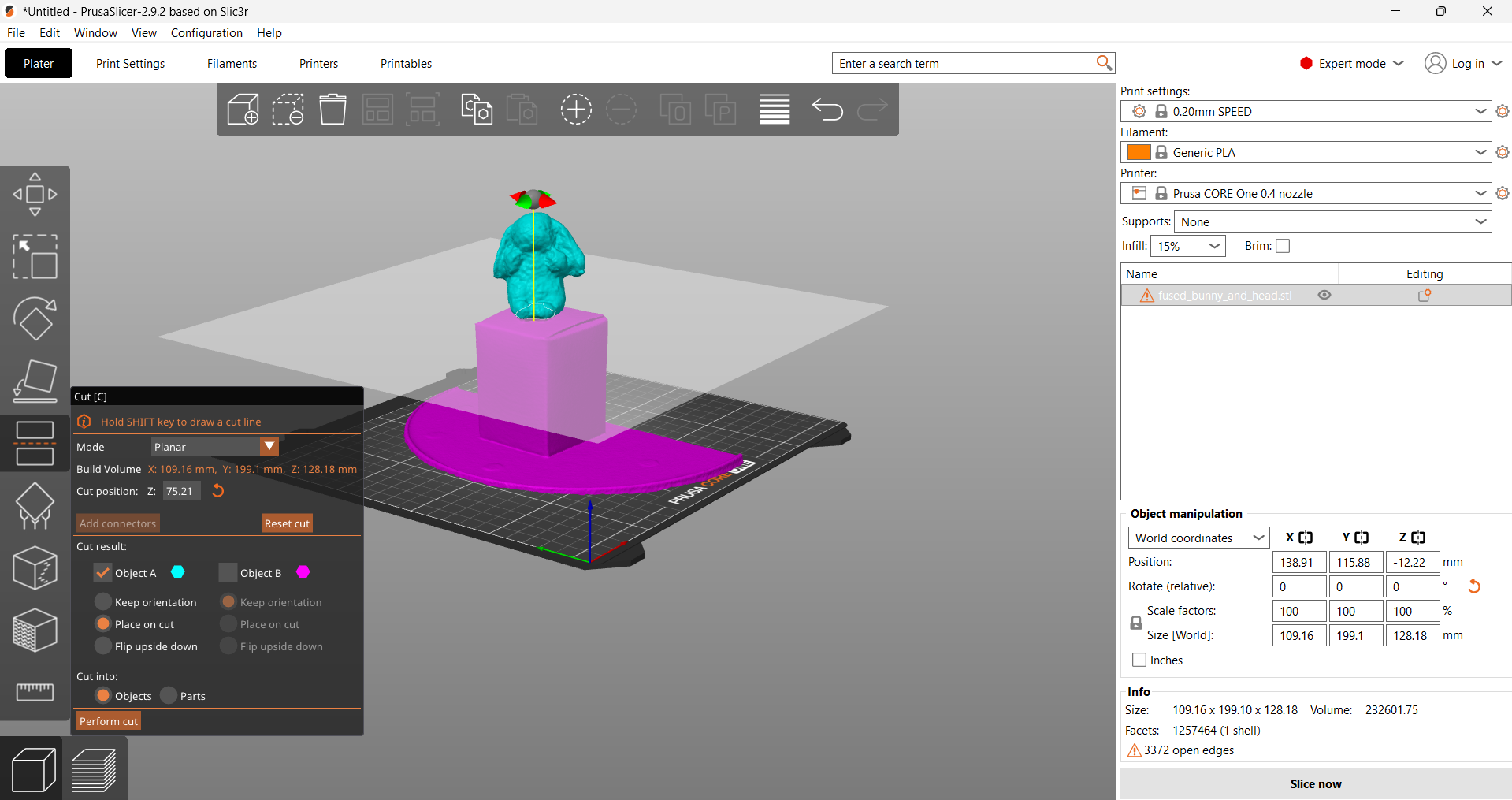
After putting the bust of Caesar next to the bunny, it scanned much better!
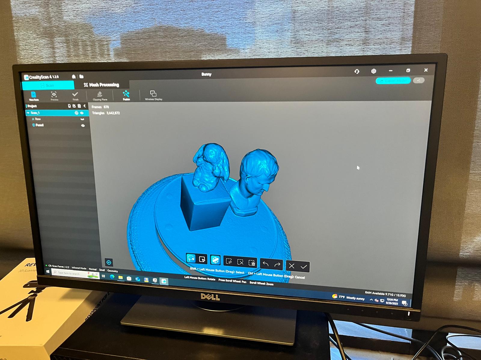
Sticking to what I knew, I just used the Prusa Slicer to crop out the bust and platform from the bunny.
And here is the final bunny:
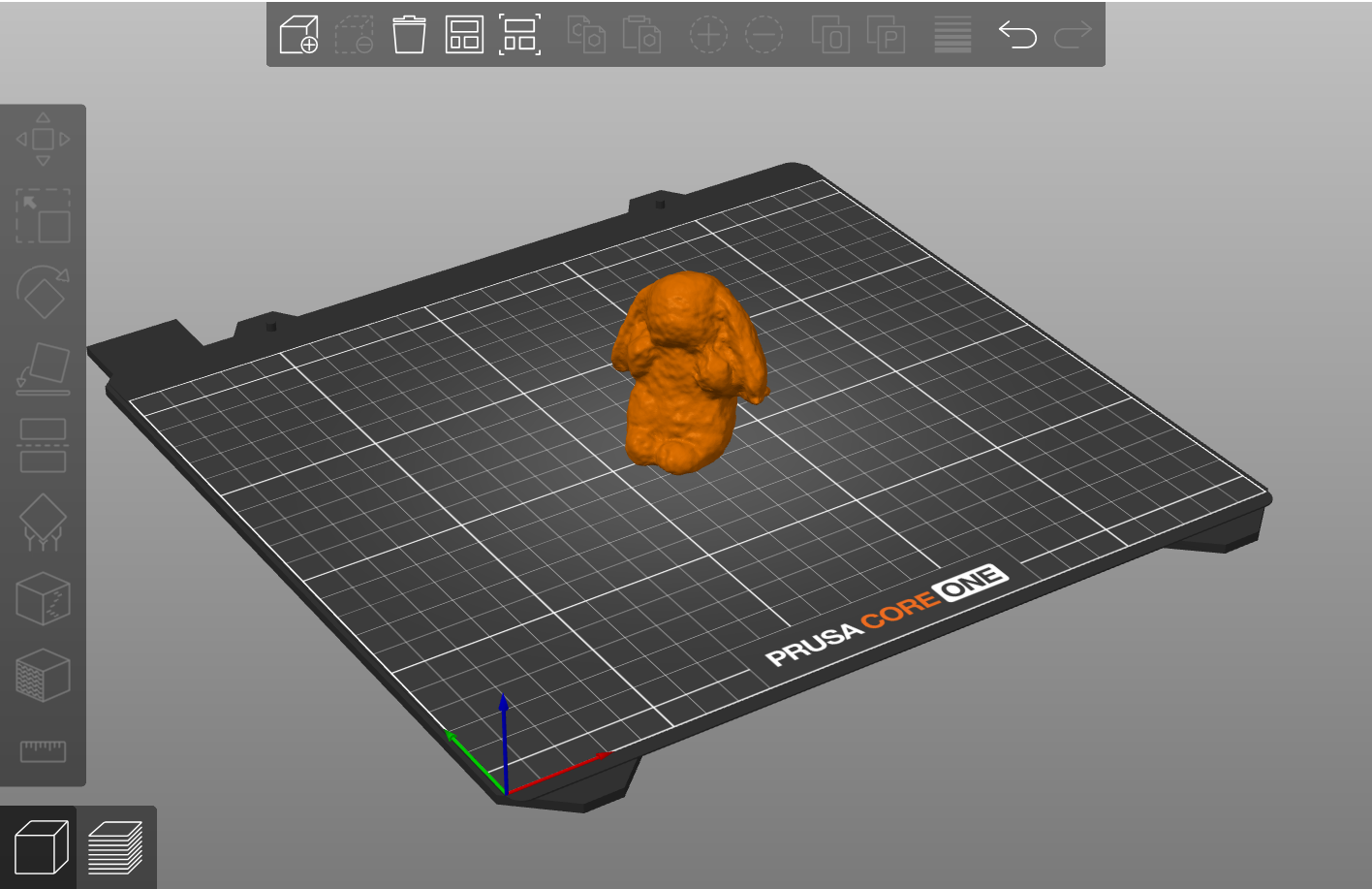
Lumpy and misshapen, but still generally bunny-looking!
A fun week, and now have some valuable information for designing my final project with :)