HTMAA 25
home about me final projectThis week’s task was to use an EDA tool to design an embedded microcontroller system and simulate its operation.
Found here: https://fab.cba.mit.edu/classes/MAS.863/EECS/Week4.html
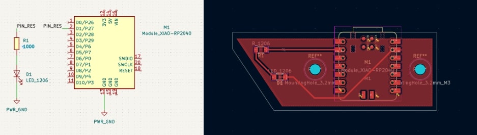
Having never used any kind of EDA tool before, my first course of action was to follow Quentin’s tutorial from recitation to design my first PCB in KiCad, whose sole purpose in life is to allow the RP2040 XIAO to light up a single LED:
To get an idea of how other tools worked, though, I also decided to try following Anthony’s tutorial to create a slightly more complicated PCB in Eagle, which is included in Fusion 360.
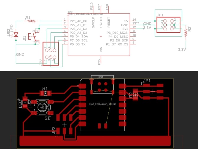
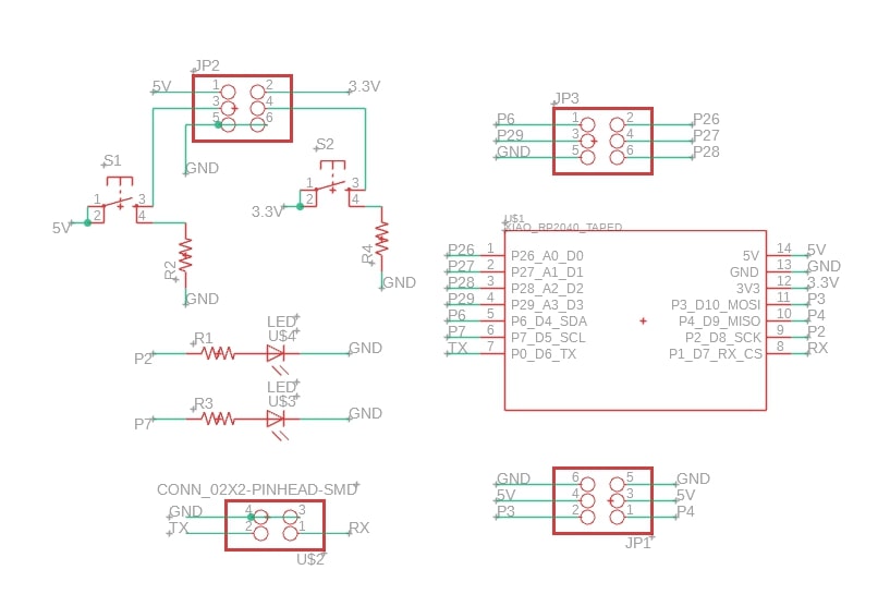
This one also includes the RP2040 XIAO, but now includes a switch to control the LED and some breakout pins to connect arbitrary other components to the microcontroller.
I really wanted to like KiCad more - I like the idea of open-sourced software, and I dislike Fusion’s cloud-based situation. However, Fusion was (surprisingly??) the more responsive/less laggy software for me, had slightly more powerful automatic rerouting, and required a little less mental overhead in terms of needing to remember to update/refresh things. I do dislike how Fusion’s dialogs take up so much screen space, and found it odd how it tried to require us to join the microcontroller grounds together while KiCad did not.
Since I’ve set up all the libraries for both, I might try KiCad again for my final project PCB. This week, though, I want my frustrations to be more design-related rather than software-unfamiliarity related, so I’ll go with Fusion.
I wanted to make a more generally useful breakout board that I could plug things into, but just routing all the pins to connectors seemed boring. I decided to try a different shape:
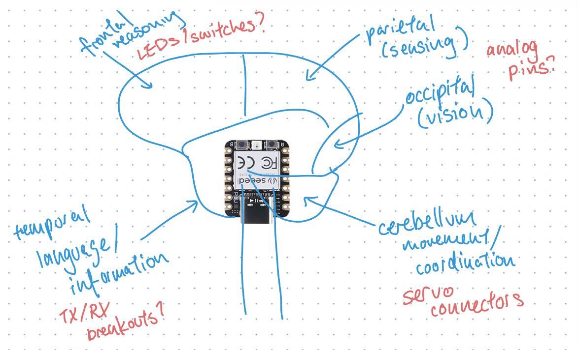
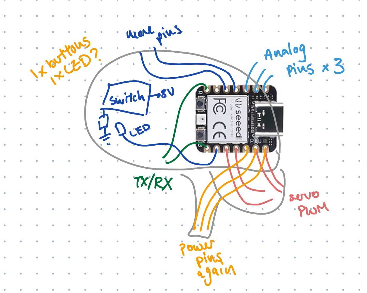
My first idea was to riff off of the computer-as-brain metaphor and literally make the PCB in the shape of a brain. To add an additional constraint, I thought of actually trying to push the symbolism and have the lobes of the brain correspond to connectors and/or PCB components, and created the above diagram. In my limited electronics experience, I have used TX/RX pins as well as servos with their power/ground/control lines, so I thought explicitly grouping things like that could be helpful too.
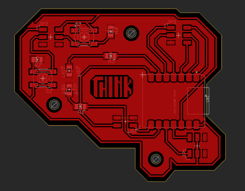
Upon trying to wire it, I had to reconsider the USB-down orientation. USB-right seemed to be more sensible for having pins reach the correct areas. I did consider seeing if I could route power pins around to the brain stem (representing energy from body -> brain), but discarded this idea later because of how many crossovers it’d introduce.
I played it very safe with components from the fab library, using the XIAO RP2040, LED1206, R1206, and CONN_03X2-PINHEAD-SMD components that were used in the tutorial. I also used a single CONN_02X2-PINHEAD-SMD, reasoning that it would be similar enough to the 3x2 variant.
I used 16mil clearance and 16mil trace width on a single-sided PCB.
My first step was adding the microcontroller and a bunch of miscellaneous components I knew I’d want. I labelled all the pins of the microcontroller and connected things that had to go together e.g. LEDs and switches with their resistors. My process then went like:
I knew I wanted a ground plane, because having lots of ground is useful. However, I had a breakthrough when I realized that power lines (which were also useful) could be routed around the ground plane and the breakout pins, since the pins didn’t have to be all the way at the edge of the board. If I outlined the brain with the 5V and 3V pins, I could access those voltages in the prefrontal cortex.
After routing everything, even with adding one more switch and LED than I intended, it turned out I still had a decent amount of empty space - there just aren’t that many pins on the RP2040 XIAO. I decided to then fill the empty space with a few m3 mounting holes as well as a little polygon graphic.
I drew the shape of the board last, following the power traces.
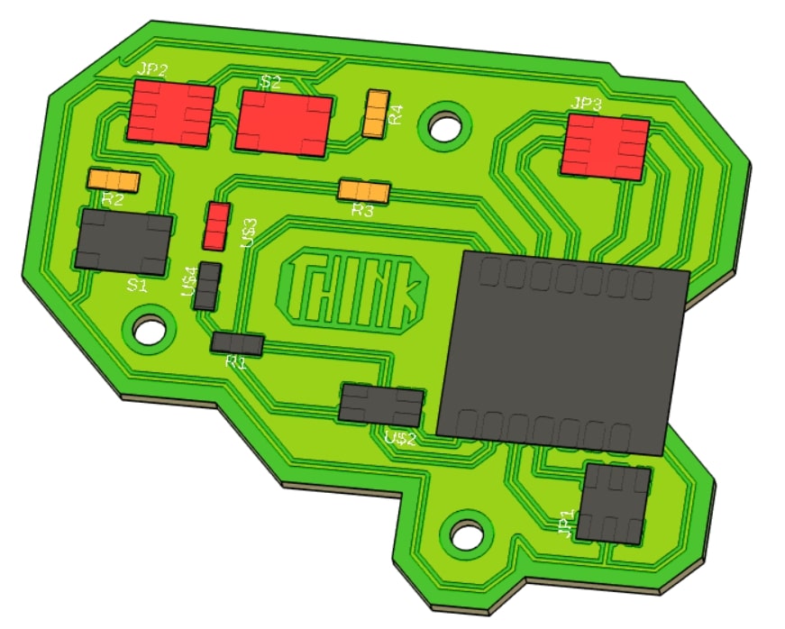
Fusion also allows you to pretty straightforwardly convert the 2D PCB to a 3D model, though the components stay as colored placeholders:
Fusion file can be found here: brain_board.f3z
My board doesn’t really have much connected on it at all, as most pins are just linked straight to a connector. Hence, for my simulation, I just chose to simulate the LED and the switch (button) mechanisms.
I used Wokwi, with a Arduino Nano board (there were no XIAO boards, though I probably should’ve used a Pi Pico). I linked up one switch and one LED in an equivalent manner to what I did in my schematic and wrote a small LED blink script.
#define LED 11

void setup() {
  pinMode(LED, OUTPUT);
}

void loop() {
  digitalWrite(LED, HIGH);
  delay(1000);
  digitalWrite(LED, LOW);
  delay(1000);
}
Then ran the simulation:
It works!
I was a bit intimidated at first, but once everything was set up it was pretty smooth going. All in all a fun week!