Designing and cut a modular construction kit on the lasercutter.
Characterizing the lasercutter's focus, power, speed, rate, and kerf as a group.
Tools
Epilog Lasercutter
Vinyl Cutter
Web Development (GitLab, VSCode, HTML)
Laser Cutting
Group Assignment
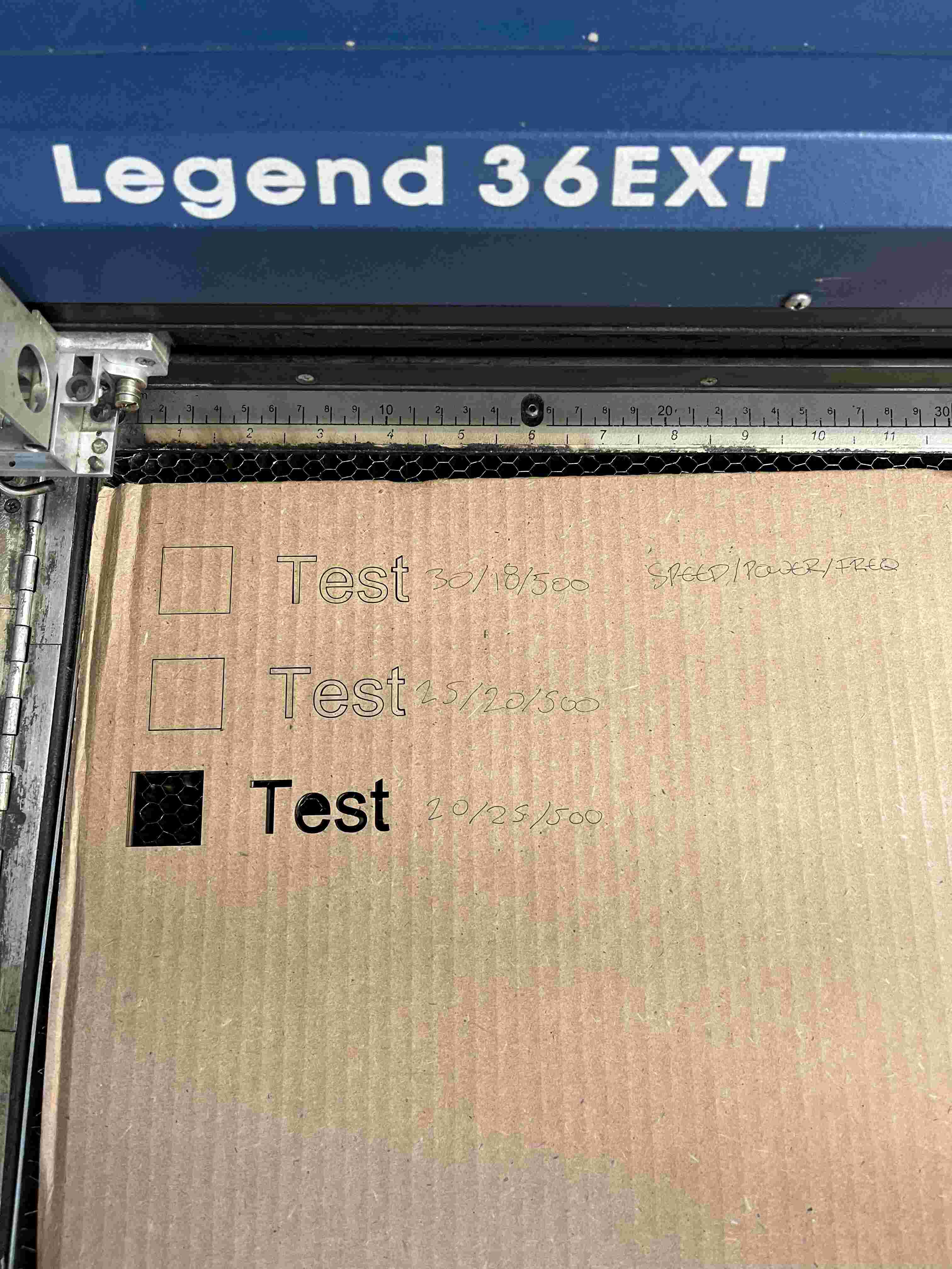
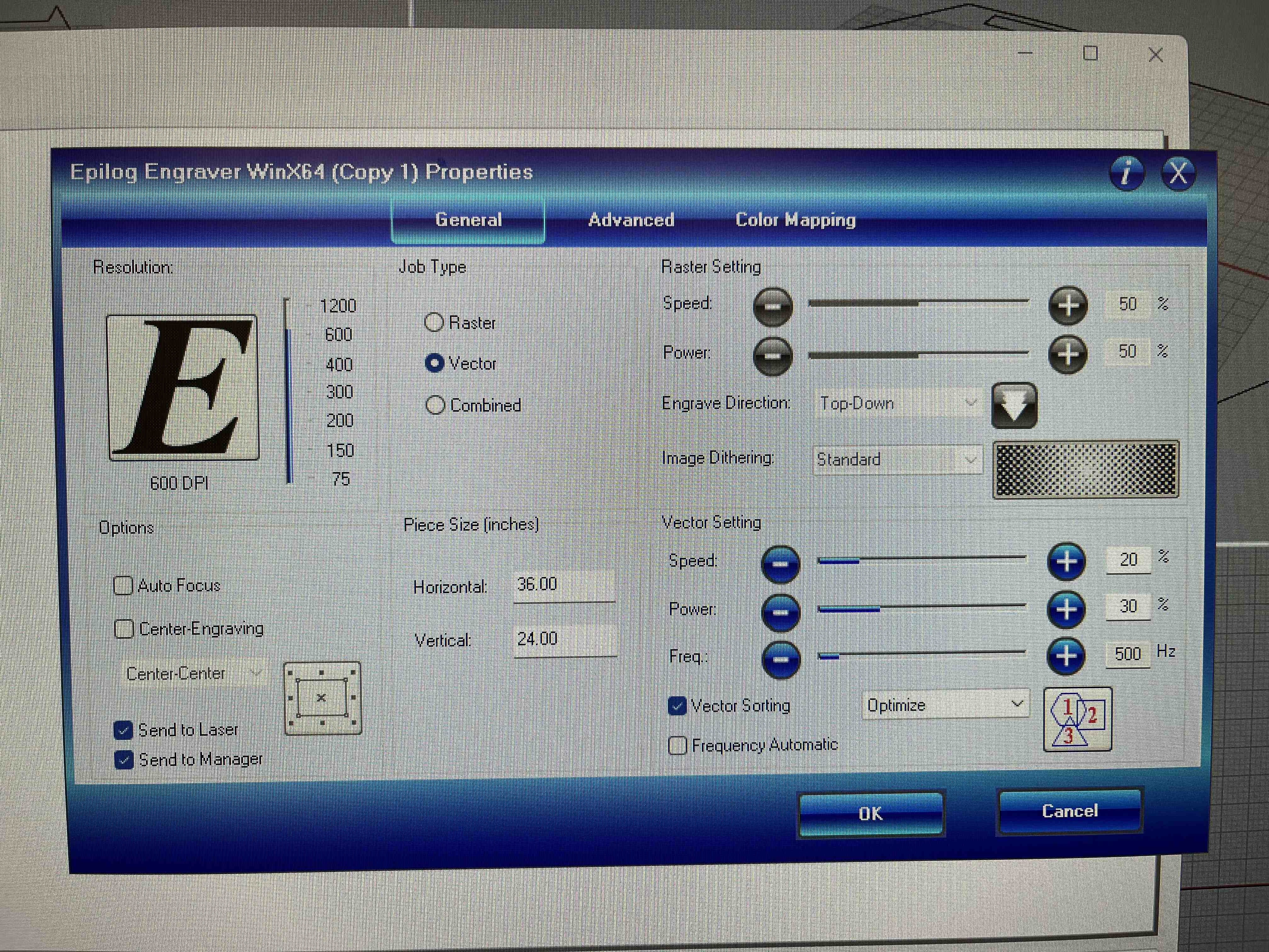
As part of our lab training in gaining familiarity with the laser cutter, we had to characterize and document the laser parameters for cardboard cutting. The wall by the laser cutter has a sheet outlining the rough settings guidelines for each material, which in our case was 3/16" thick cardboard. We ran several passes to test the optimal settings that cut through the material cleanly without charring it.
Focus: The laser is angled to form this hourglass shape which concentrates the beam 2 inches below the metal plate. In calibrating the focus, we always positioned the center of our cardboard 2 inches below the plate for a clean cut. Therefore, the top surface of the material should always be (2 - (width of material/2)) inches below the metal plate.
Power: The laser intensity can be controlled through this setting, measured as a percentage of maximum power, and is often adjusted in conjuction with speed. We started with 18% and scaled up to 28% to find the optimal setting.
Speed: Similar to power, the speed power can be adjusted as a percentage of the maximum. Lower speed is analogous to higher power as the material cut is greater. Our speed settings began at 30% and slowed down to 20%.
Rate: The laser emits a high-powered beam at a given frequency, which can be adjusted via this setting. If the frequency is low enough, the laser cut pattern will be quite botchy. We kept the frequency stable at 500Hz for cardboard.
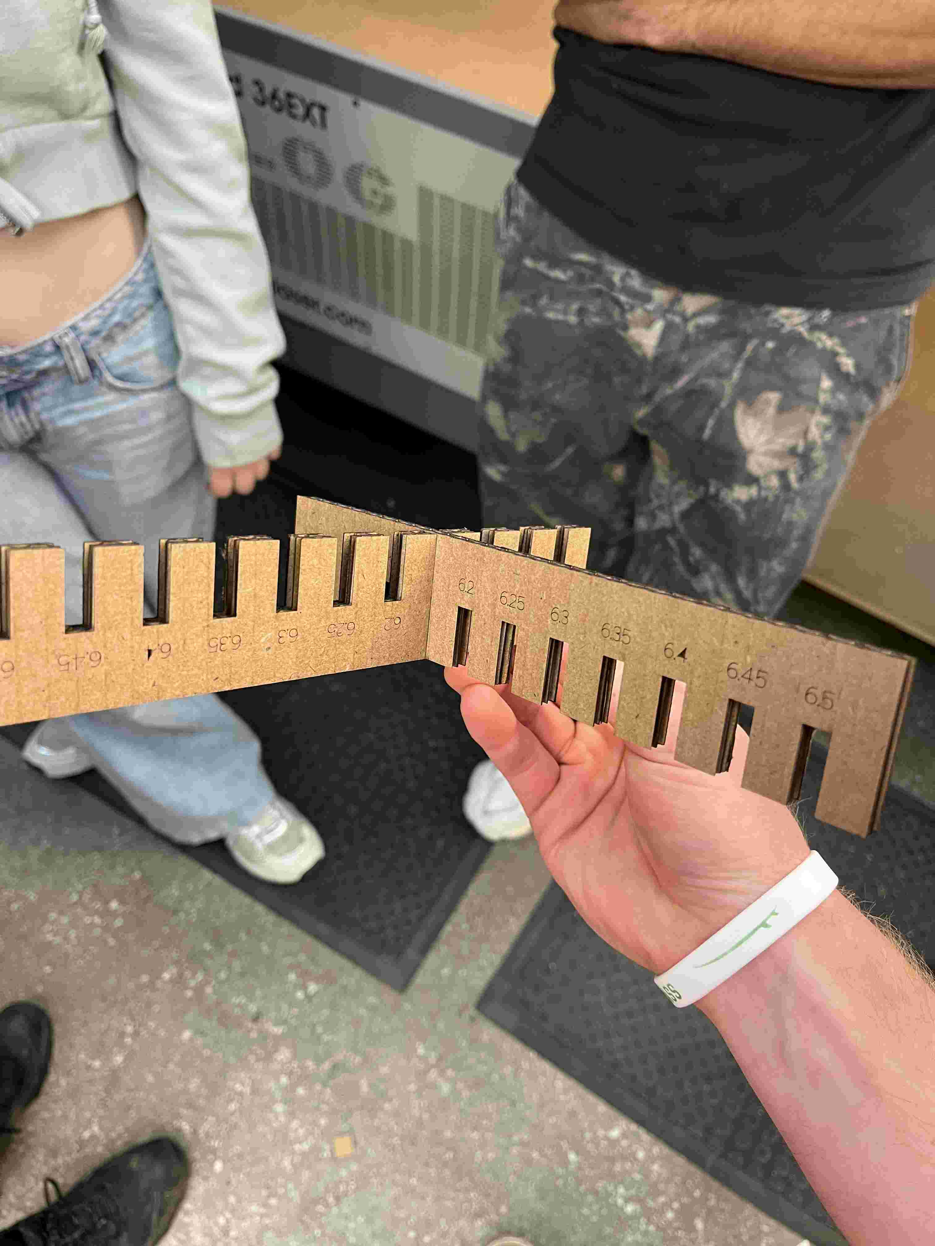
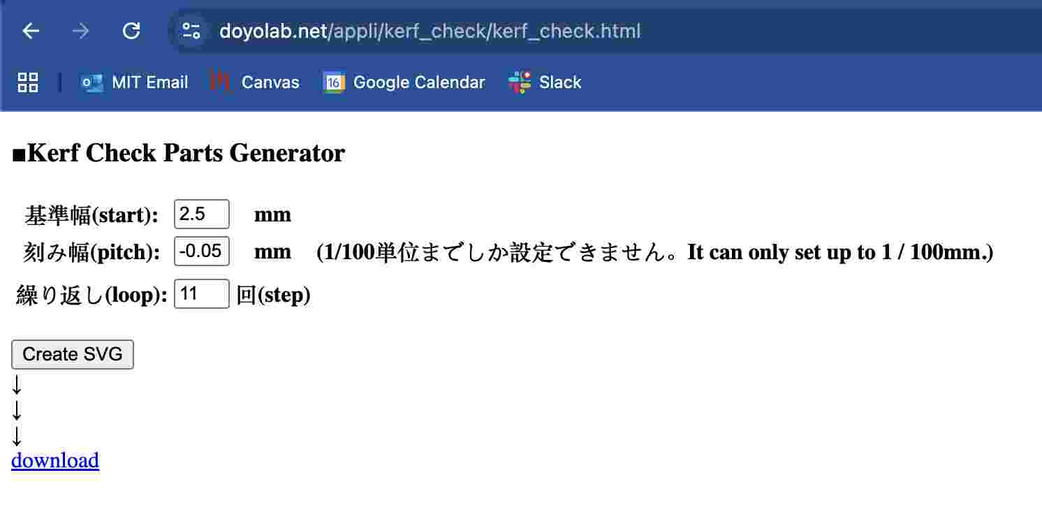
Kerf: Because of the inherent width in the laser beam, a small kerf must be adjusted for when designing patterns to ensure a snug fit. We utilized a Japanese open-source kerf checker generator (Doyolab) that increased width incrementally to characterize the laser kerf. By matching this resulting pattern we found this laser kerf to be ~0.14mm.
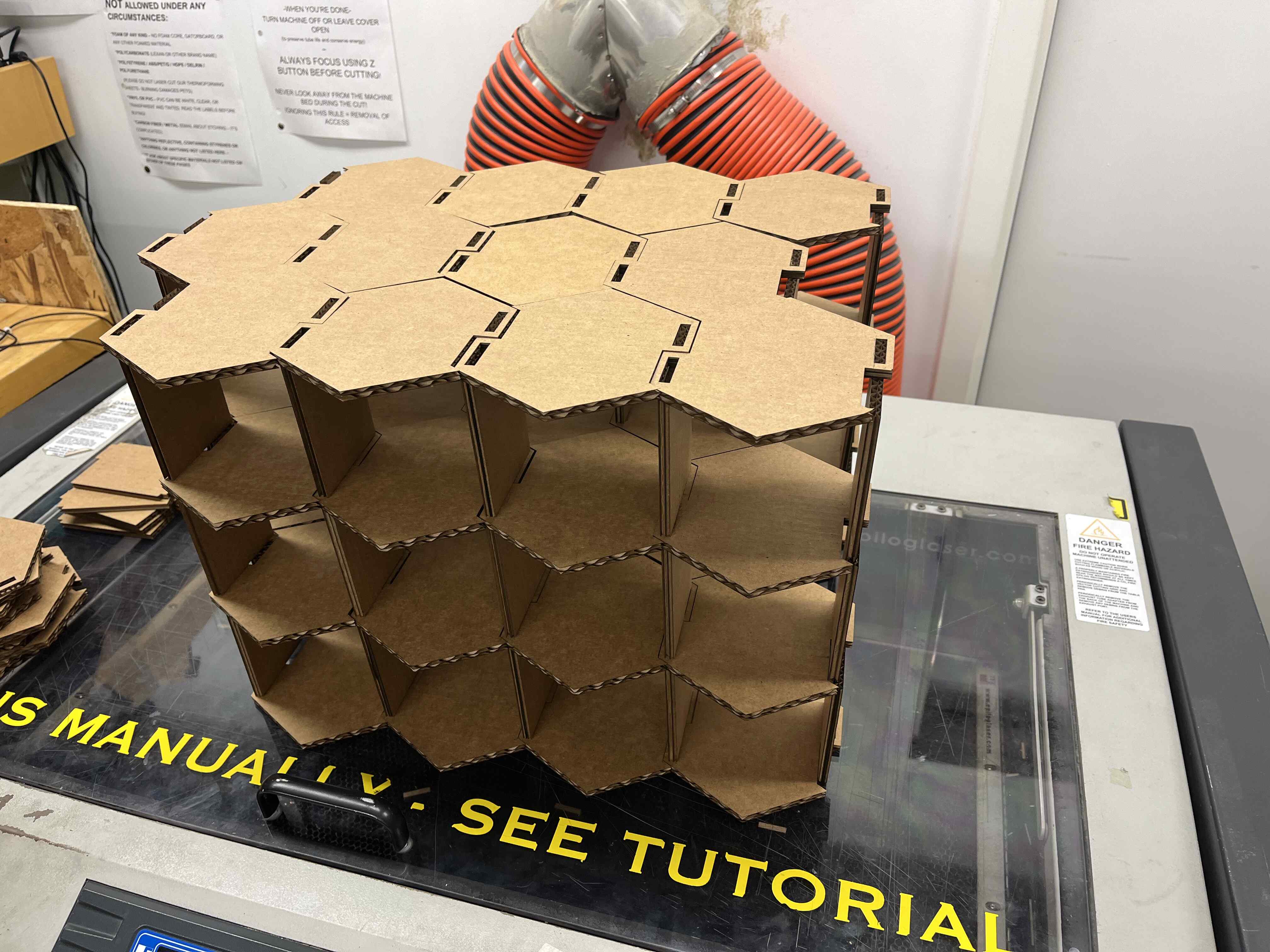
My goal for this semester is to have every weekly assignment inspired by the natural world. For this part, we had to design a parametric construction kit by laser cutting a few components that can be assembled into numerous structures. Nature is full of great builders, but the one I emulated this week was bees! I wanted to design modules that assembled into a honeycomb structure. It is also noteworthy to point out that the hexagon (the key honeycomb design) is one of the few shapes, including the equilateral triangle and square, that can perfectly tile over a flat surface without any gaps. However, the hexagon has by far the superior surface area to perimeter ratio. This allows honeybees with an optimal design for maximixing storage and minimizing the wax required. Isn't that pretty cool!?
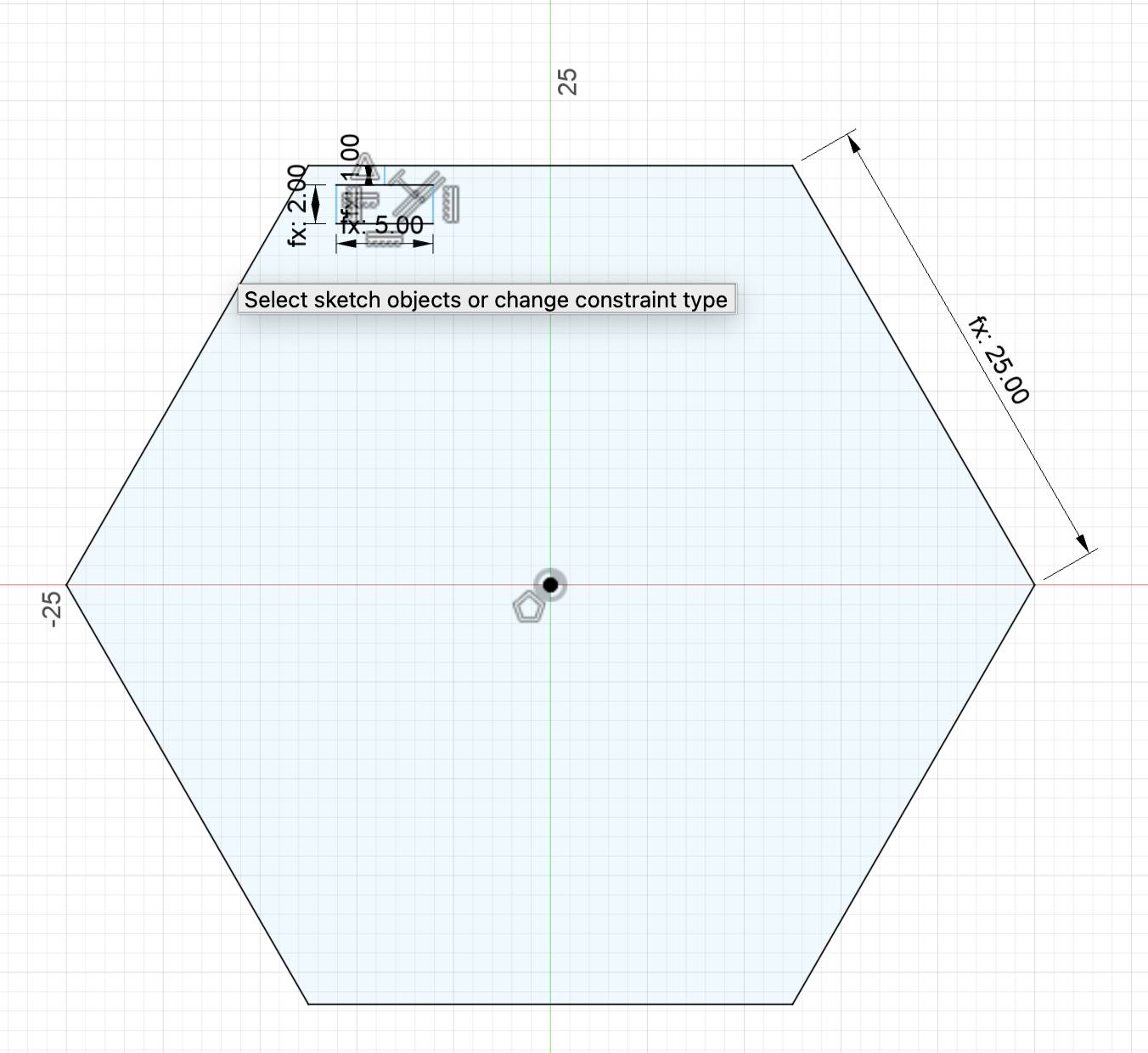
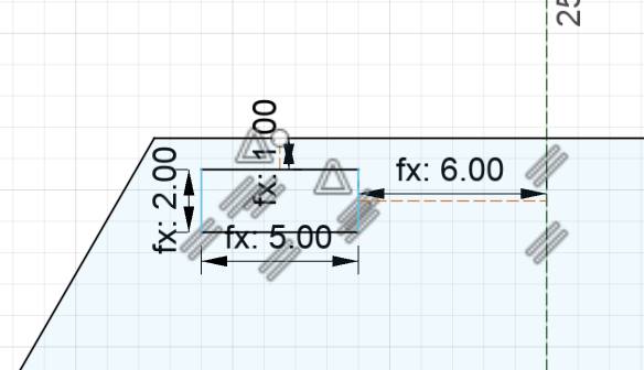
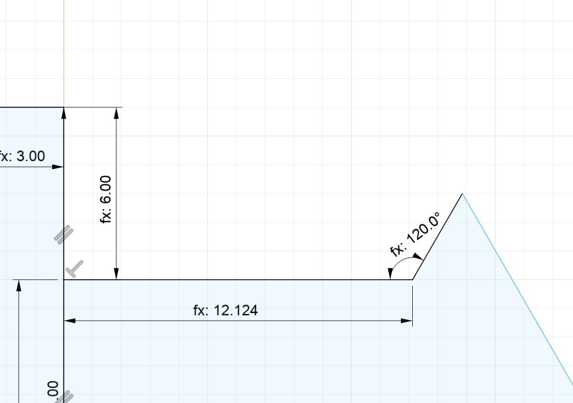
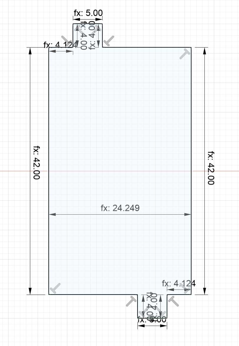
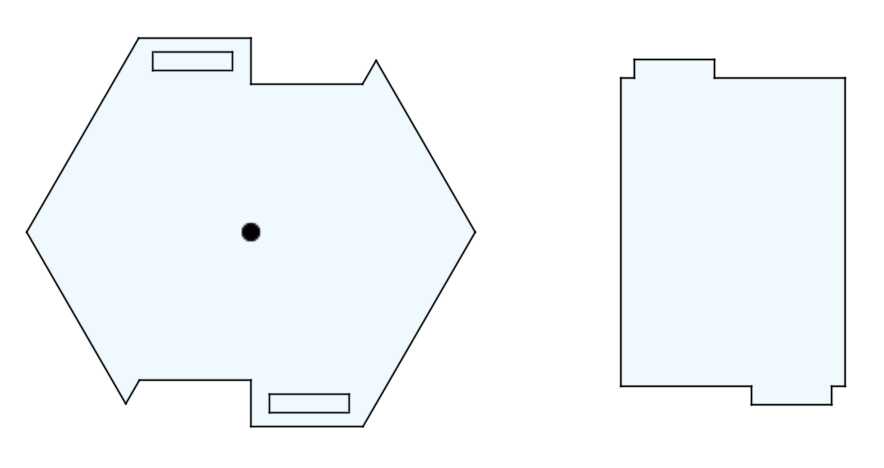
The natural companion to the hexagon in a honeycomb design is a rectangle that provides structural support and connects the hexagon components. With these two modules, I was confident that many structures could be assembled similar to honeybees. My work began in Fusion by designing and parametrizing the hexagon and rectangle pieces. I started off with a standard polygon shape and began to design the hexagon slot for the rectangle tab. My idea was to alternate slots for the hexagons to allow for strong bindings, and create a natural outline to stack hexagons on top of one another. The rectangle design was much more straightforward, with two opposing tabs to fit into the hexagon slots.
Hexagon Base ShapeAlternating SlotHexagon Outline StackRectangle Tab Shape
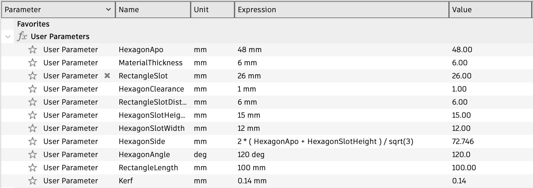
The design were parametrized to fit each other, so the rectangle tab and hexagon slot were tied to the same user parameter. Additionally, the design had to be adjusted for kerf to ensure that the fit was snug and the structure wouldn't collapse. As a result, the slot was designed to be 0.14 tighter and the hexagoin outline was 0.14mm smaller than required.
User ParametersHexagon & Rectangle Design
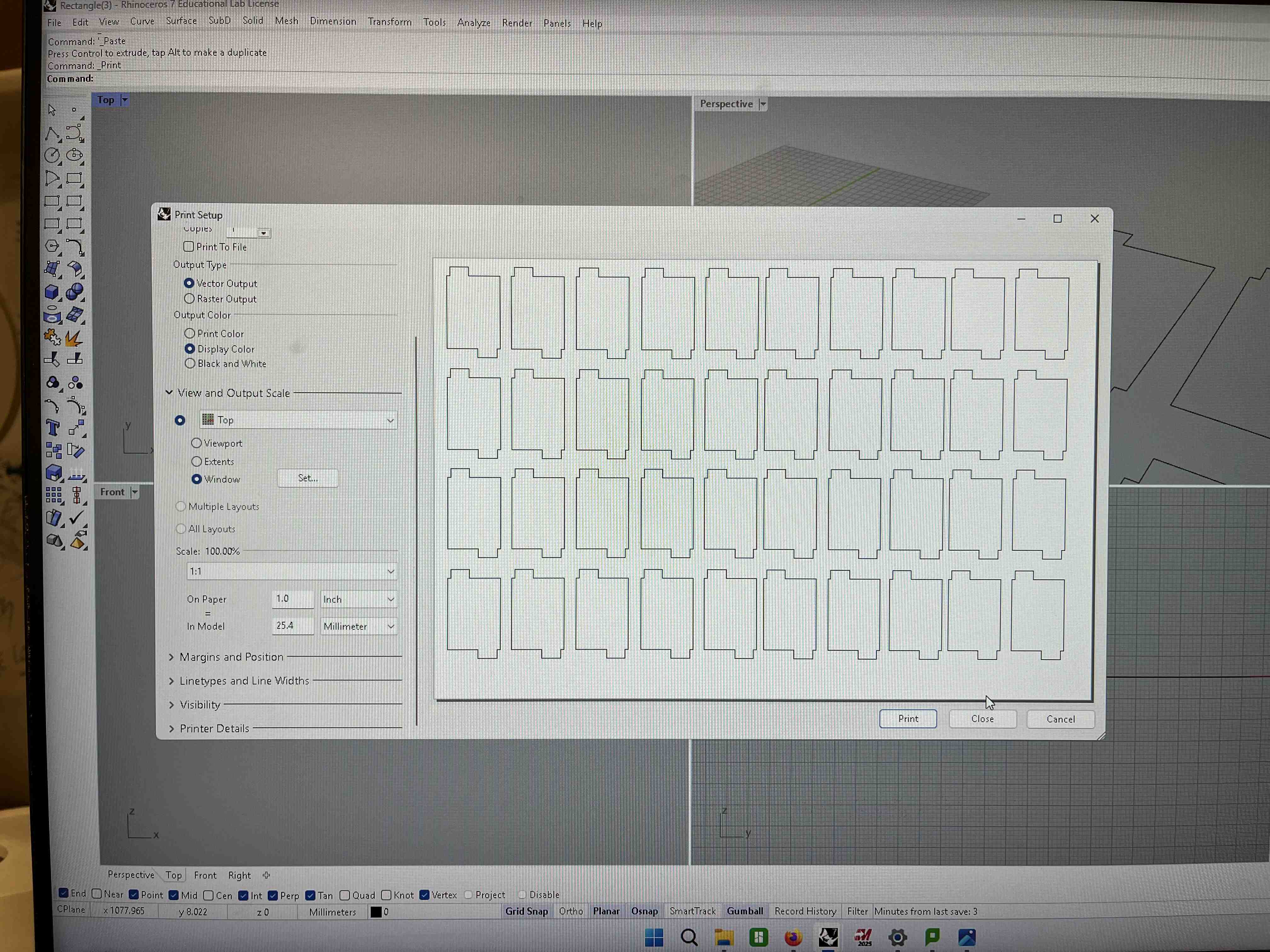
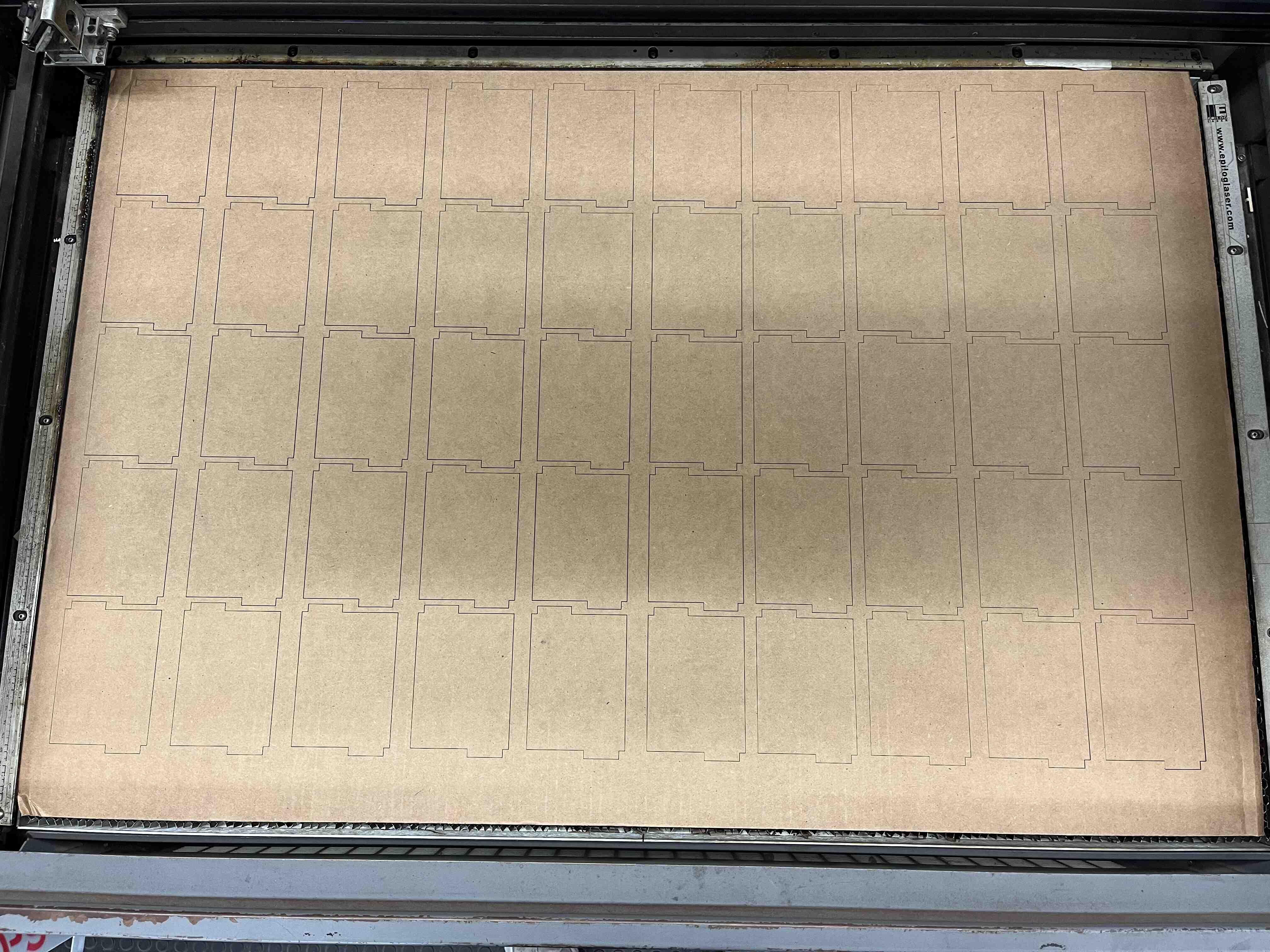
Once the CAD work was finished, I exported the shapes as DXF files and began work on the laser cutter. The DXF files were opened on Rhino and I began by analyzing the material via test runs to determine the optimal settings. Once the settings were calibrated, I began the patient work of laser cutting many rectangle and hexagon components to assemble my modular construction kit.
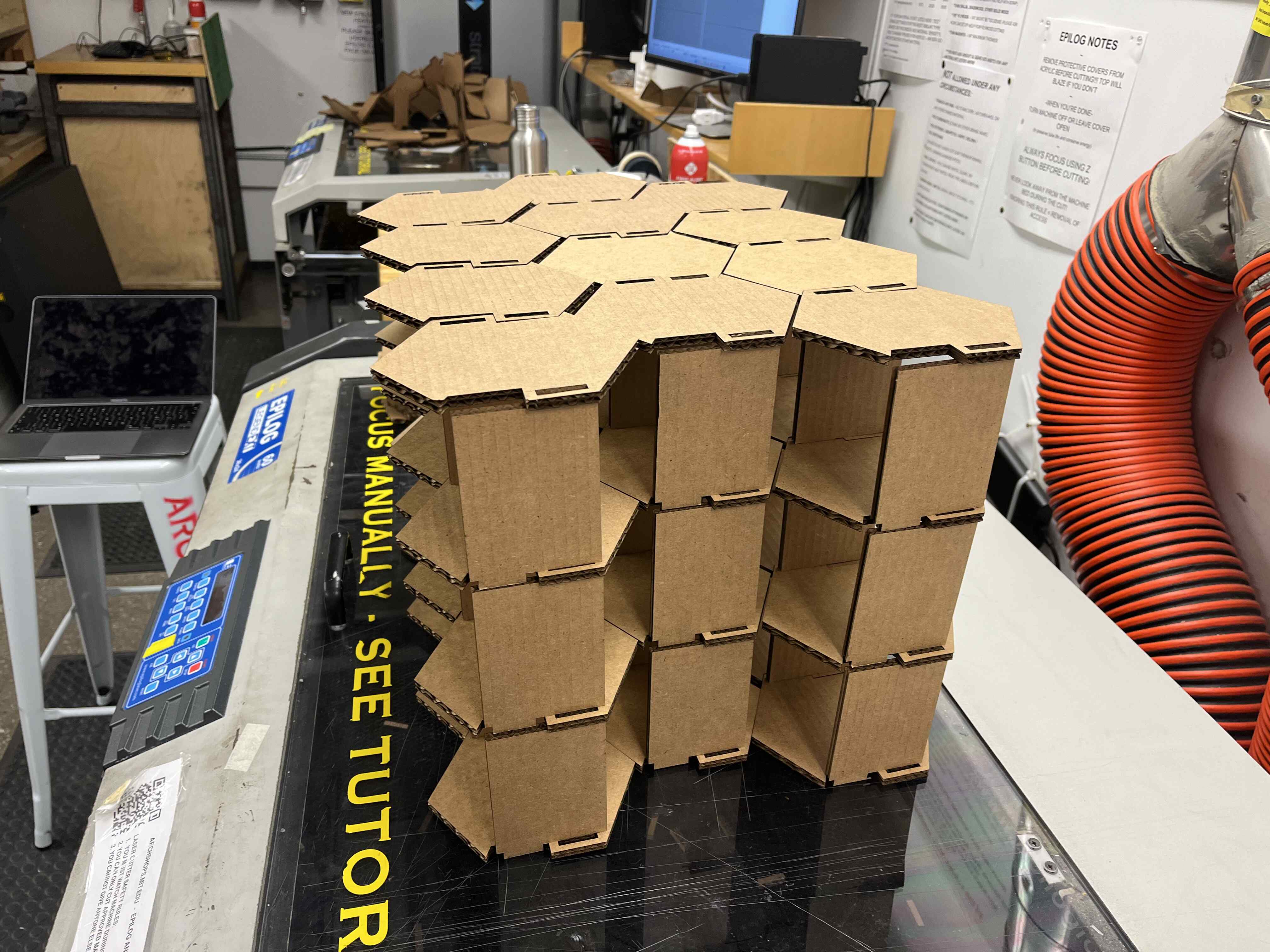
Now came the fun part: I could assemble the finished lasercutter components into a large structure. The hexagon and rectangle pieces are modular and fit into any honeycomb shape, similar to how honeybees match their honeycomb structures to fit their environment mold.
Vinyl Cutting
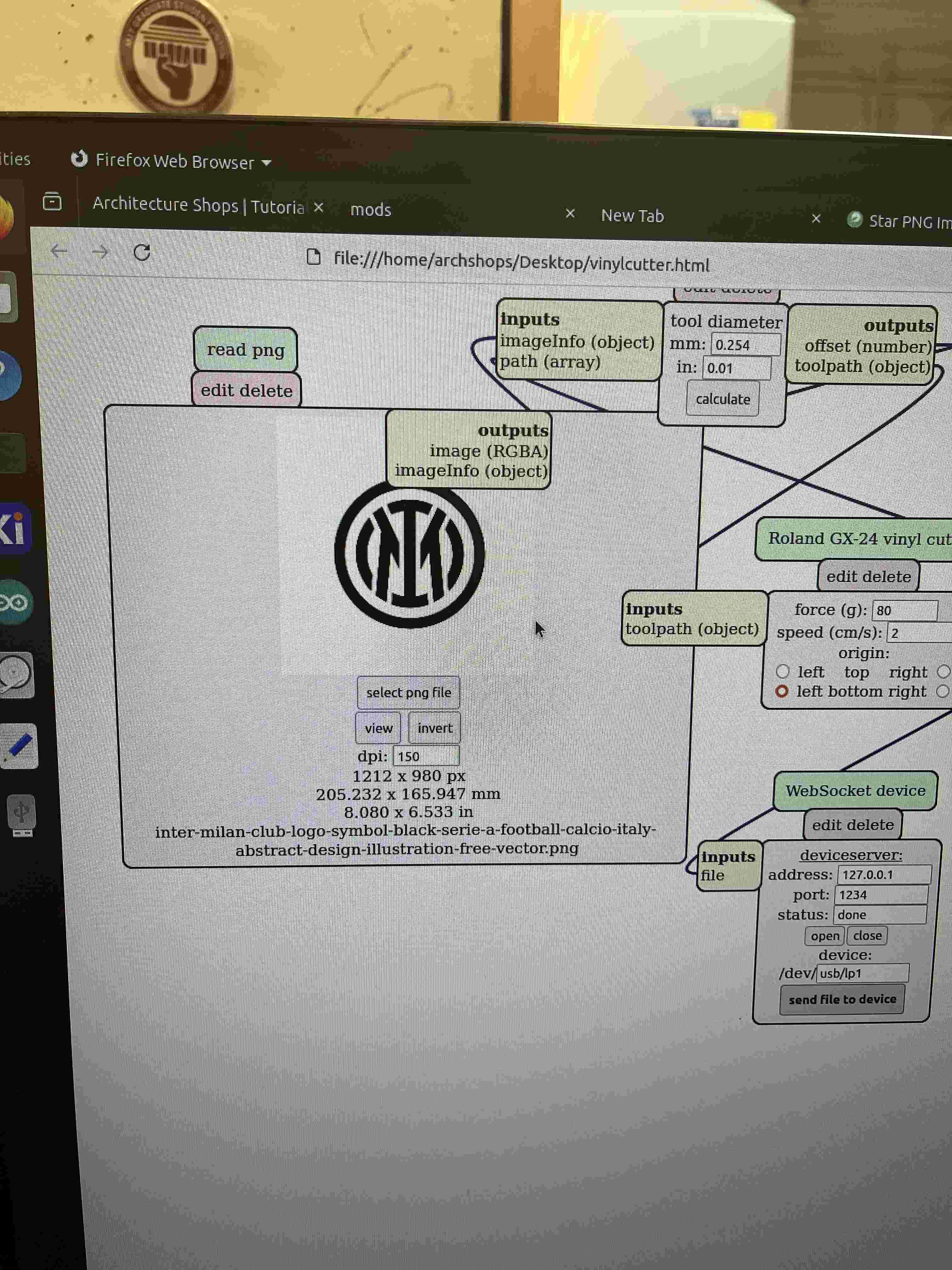
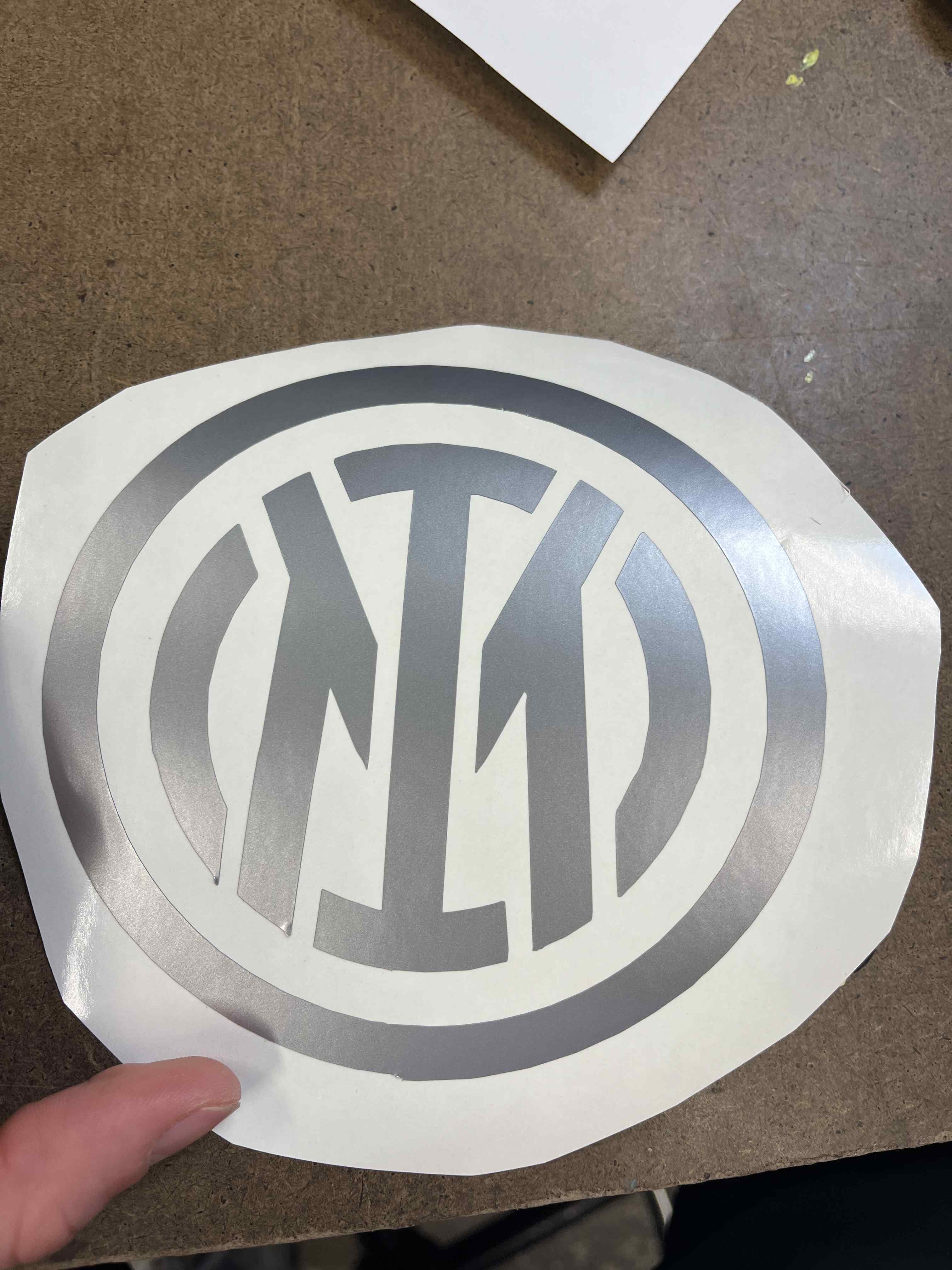
The vinyl cutting assignment was more straightforward and required less iteration. I was very committed to cutting a decal that I was proud enough to stick on my laptop, so I decided to download a PNG file with my favorite team's logo. I have been a FC Inter Milan fan since I was in the womb as it is in my blood. My father, my father's father, and my father's father's father are all Inter fans. Not many people are born with the privilege of supporting this great team.
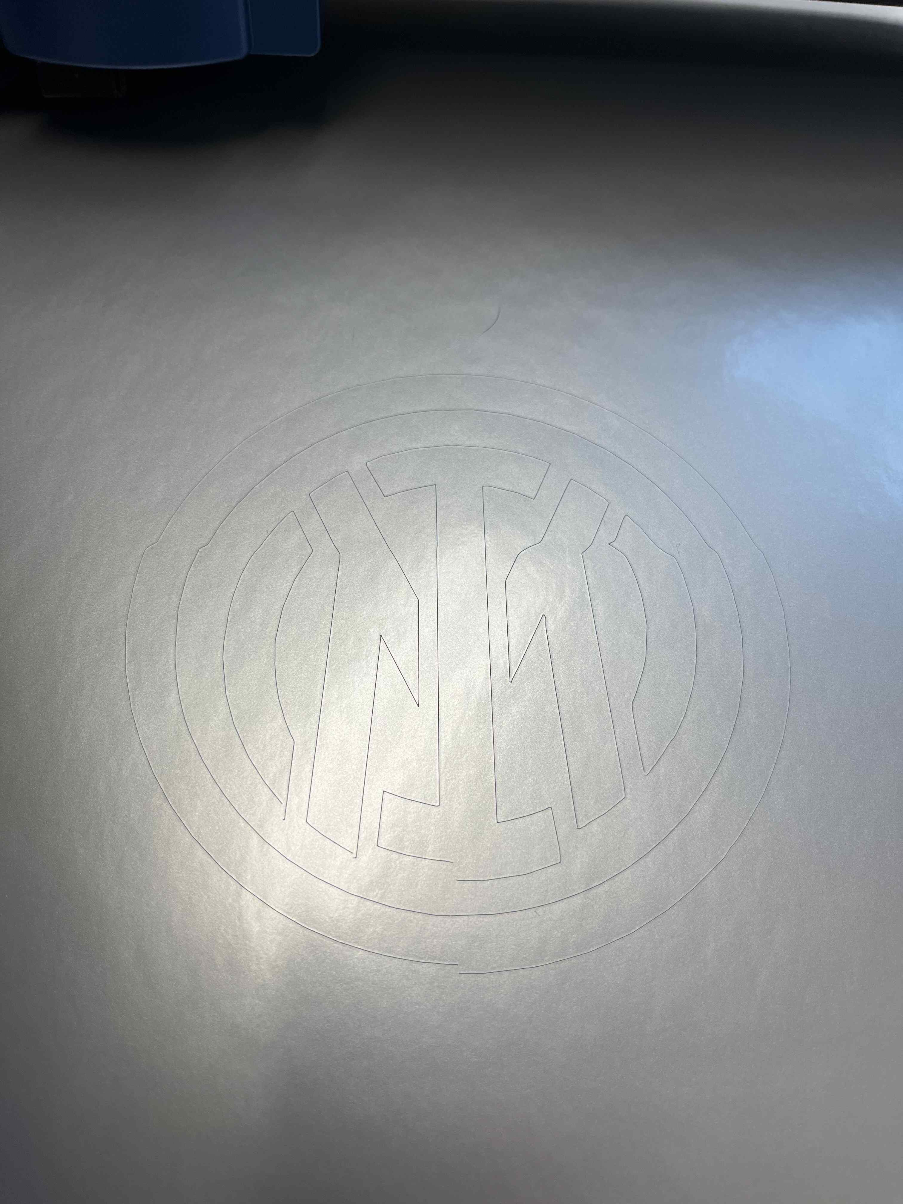
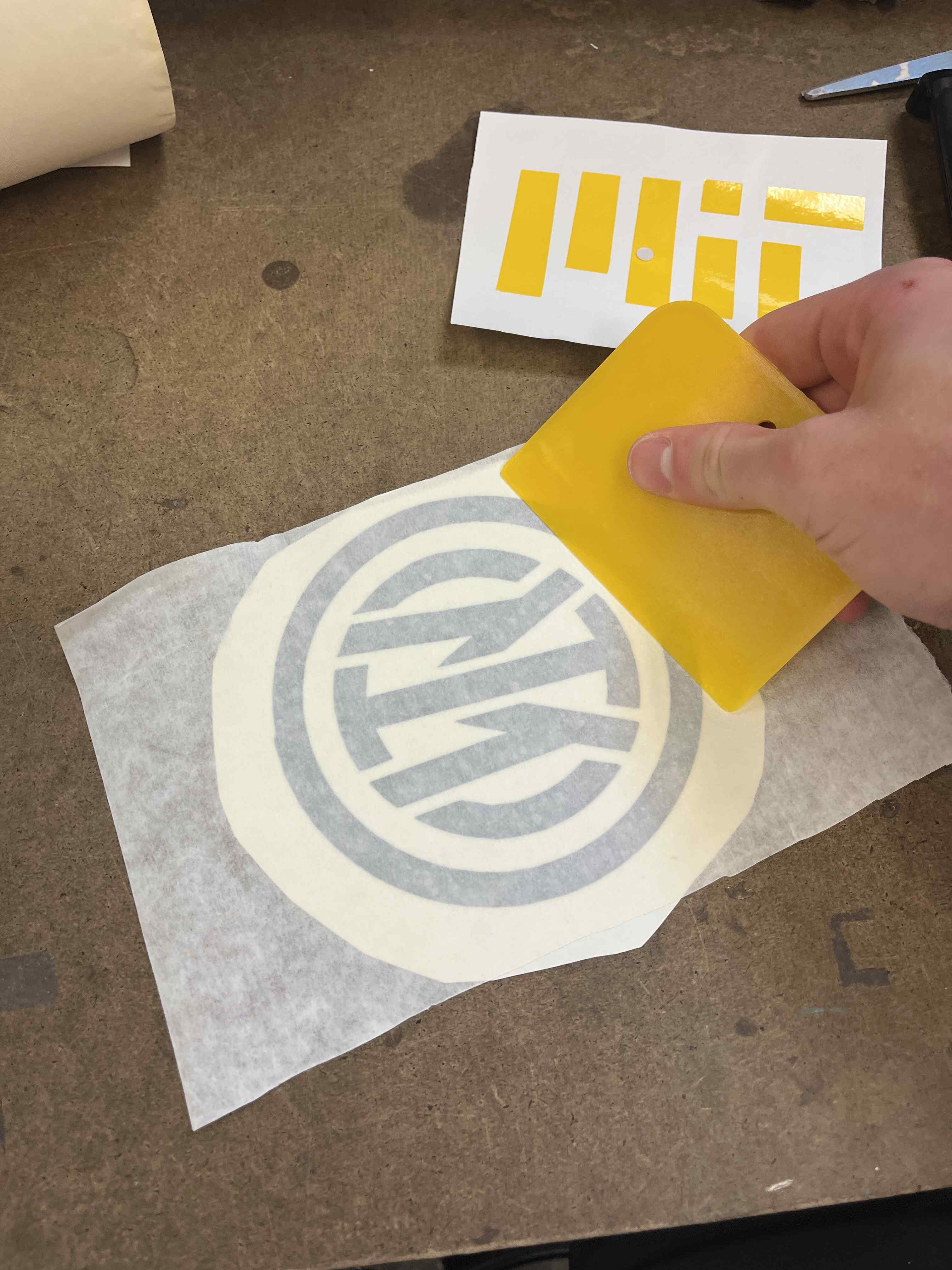
I uploaded my design to the vinyl cutter desktop and used the mods software to organize the cut. The vinyl settings were first checked by cutting a circle and square to determine force necessary. Once calibrated, I rolled the vinyl into position with the leading edge draped over the ribs, locked the wheels locked into position at the edges, set the origin of the knife tool at the bottom left of the vinyl roll, and pulled the lever up to lock the roll into position. From there, the software calculated the toolpath required and I sent the file to the cutter which executed the command. I recognized that the vinyl cutter was struggling to roll evenly with both wheels, causing the paper to bend and the design to distort. The easiest solution I came up with was to reset the origin to the center of the roll to minimize the bend created by the knife tool.
Mods SoftwareDistorted Edge CutClean Center Cut
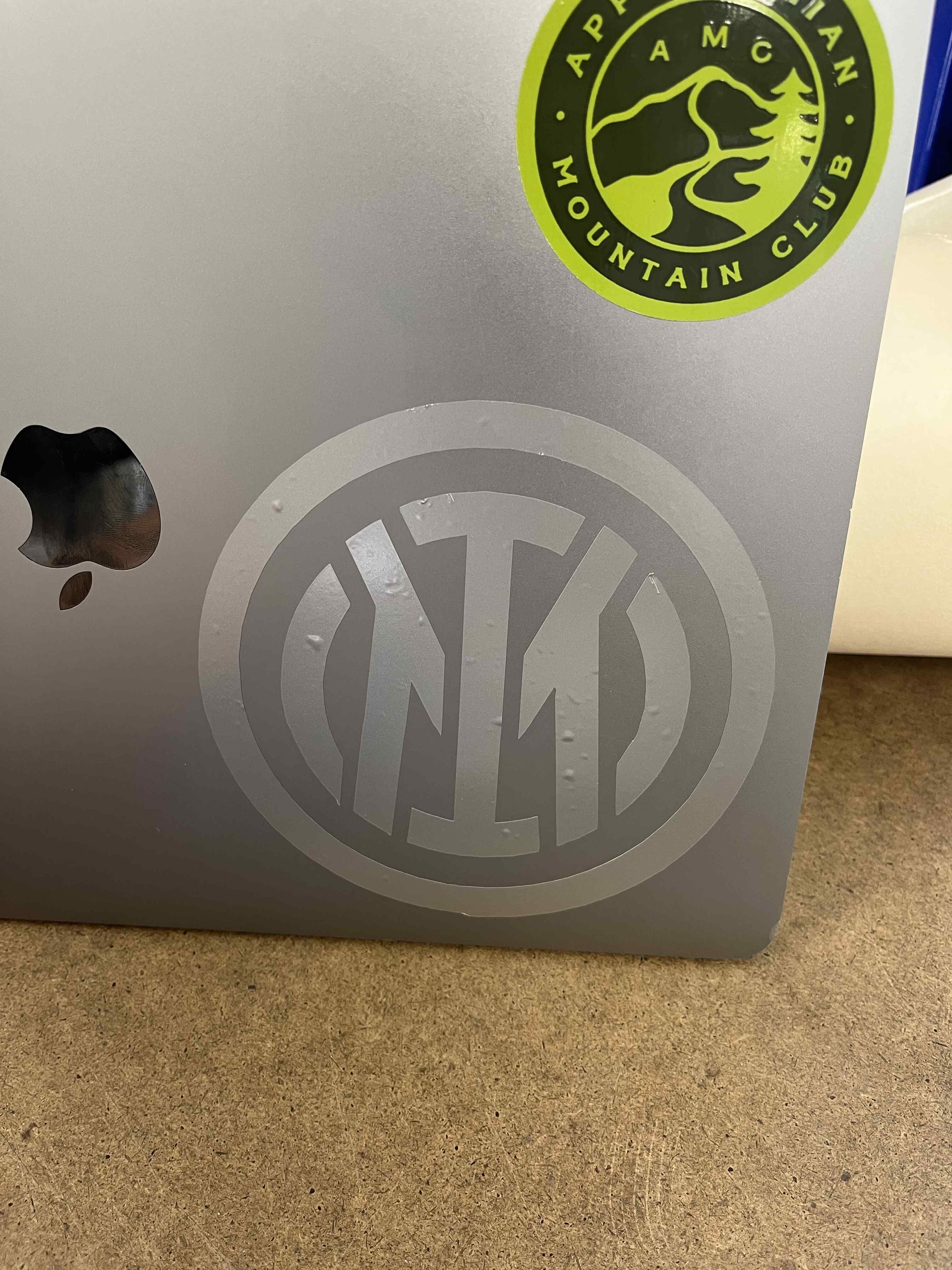
The decal was removed from the paper and attached to my laptop surface using transfer tape, tweezers, and yellow boards. I like the sleek look of the silver decal on my gray laptop; subtle yet powerful.
This week was my first time ever building a website which was very exciting! For now, I have decided to maintain an easy yet functional website for documentation, and update the design as I get more comfortable over the weeks. I have found HTML to be a very straightforward programming language so far but with a lot of options and functionality for design. My goal is to make the website design more compatible with my garden project over the course of the semester. The open source design formats have been very helpful, and I have decided to use Pico for now.
I have been relying on VSCode and Terminal as the programming GUIs so far, which I have some experience with from prior Raspberry Pi projects. GitLab is very new to me though so version control documenting has taken some time to get used to. I am very excited to have a basic understanding of website development now as it is a powerful yet simple way to build portfolios for future reference.