Documentation
Follow the documentation below to learn how to replicate this integrated system, as I describe the processes, machines, tools, materials, and components involved.
System Design
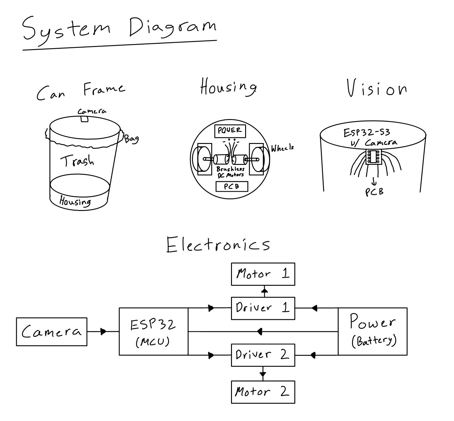
The basic idea here was automating a trash can by giving it eyes to see (camera input), legs to move (motorized wheels output), and a brain to make decisions (embedded microcontroller programming). My initial stretch goal was an auto-aiming trash can that could detect trash thrown in the air, calculate the motion in 3D space, and move to catch it. However, I soon realized that the MCU available in the inventory (ESP32S3 Sense) was powerful enough to run an object detection model but not very fast. In fact, my CV model had an inference time of roughly 150ms, so by the time the robot took a picture, processed the input, and calculated hte global position of the object, it would have already been on the floor. With that major constraint, I decided to build a robot that is more of a walker than a catcher. I began designing the rough layout sketch for my device.
Mechanical Design
At first I wanted to 3D print the full system. This way I could perfectly designing the wheel mounts, motor brackets, electronics housing, and cable management. I spent a good amount of time designing the full 3D CAD on Fusion 360, integrating 3x NEMA17 motors, 3x GoBilda Omni-Wheels, and the ESP32S3 Sense module.
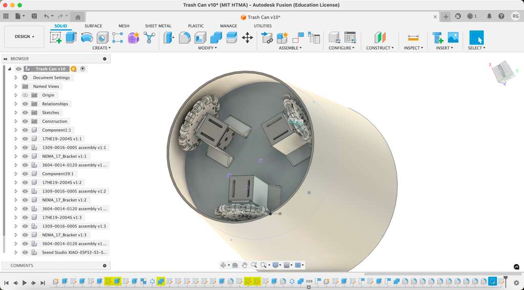
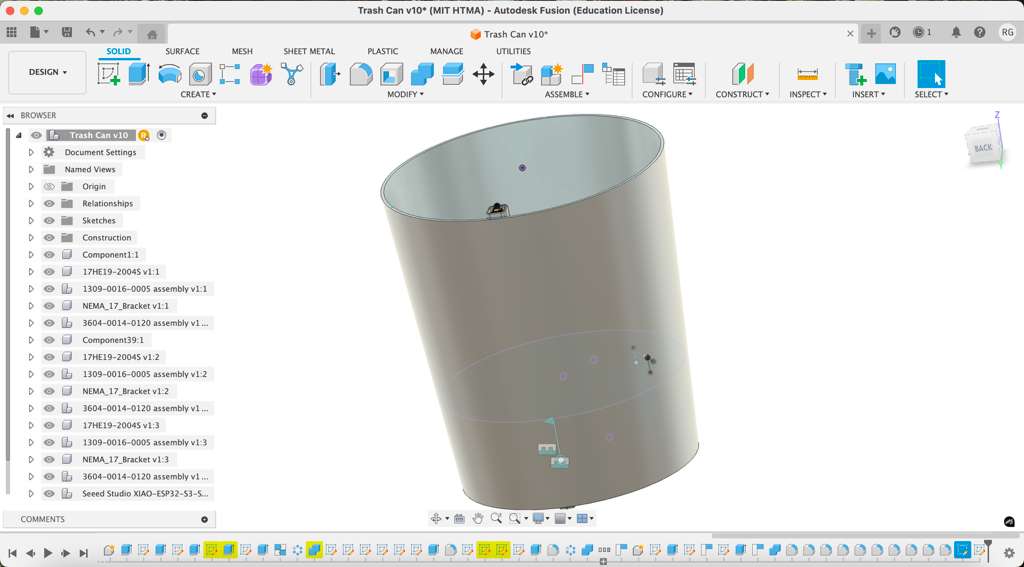
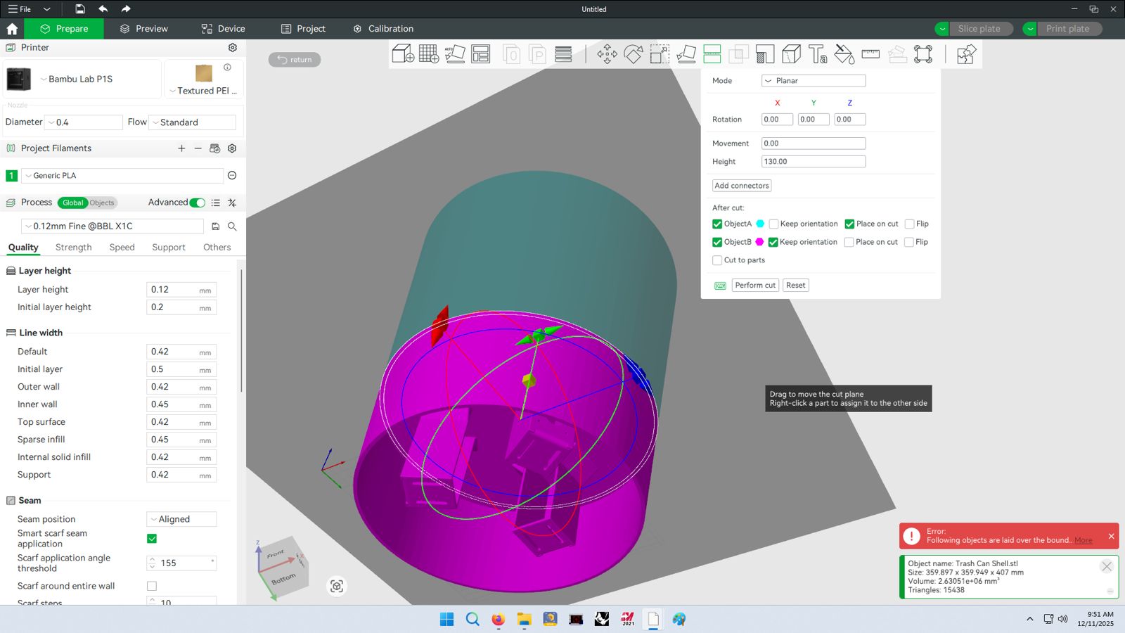
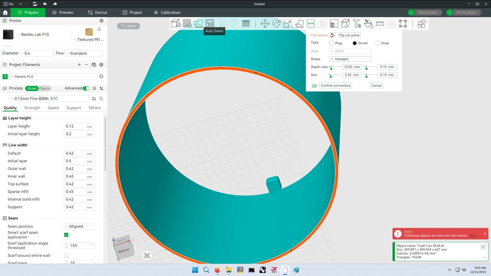
I exported the file as an .STL and brought it over to Bambu Studio software for printing layout. The design was huge, over 400mm in height and 360mm circumference. I spent a couple hours learning how to appropriately split large components in the Bambu software using the Cut function and generating connectors. The final idea was to split the trash can into 6 different pieces, first by slicing it in half horizontally where the motor bracket screw into and then each pie would be divided into 3 equal modular slices. The vertical connections betweem the two halves were designed with hexagonal dowels and the horizontal connections between slices were lap joints with screw holes.
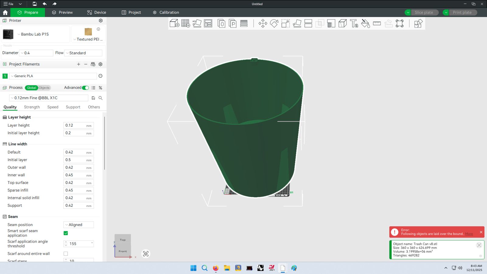
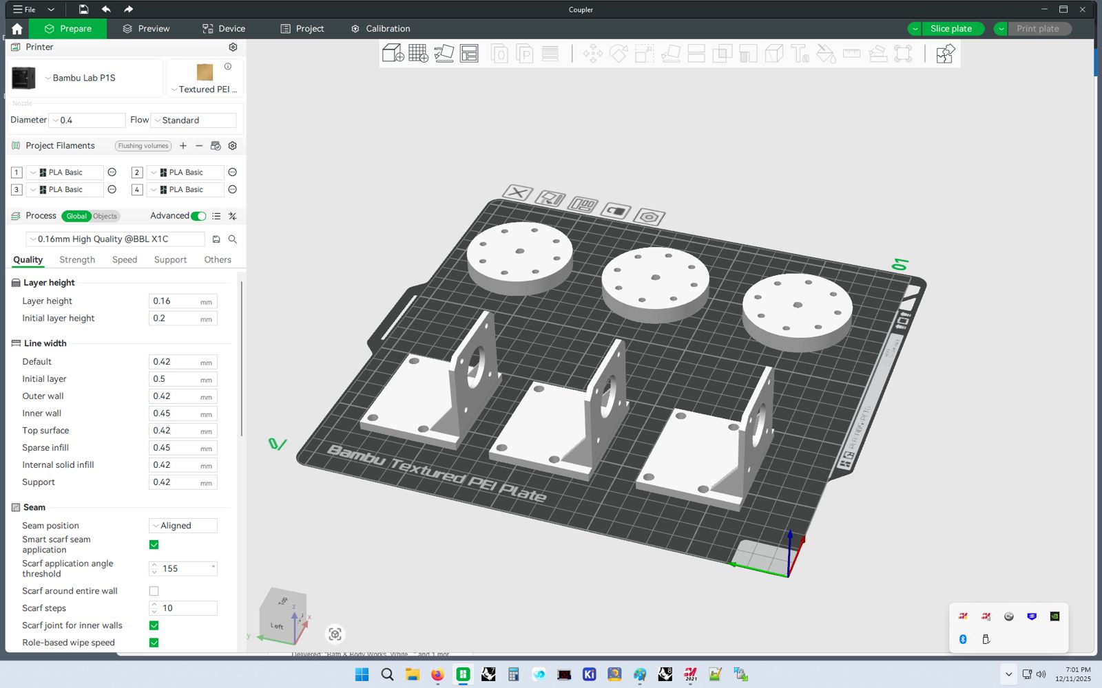
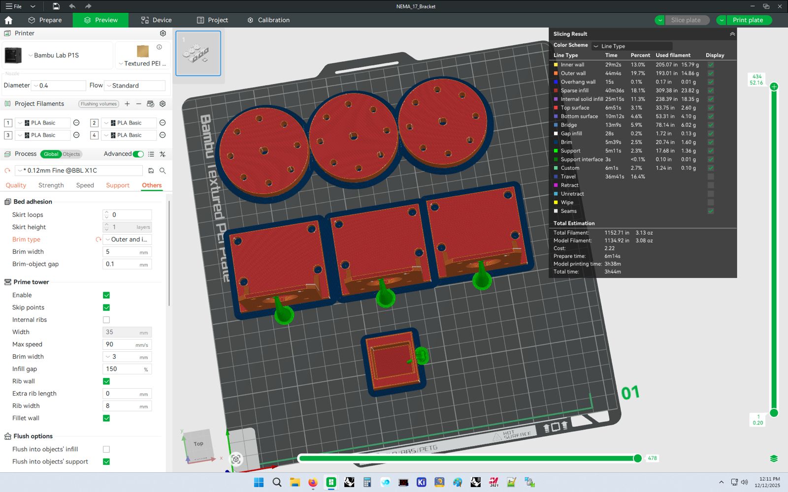
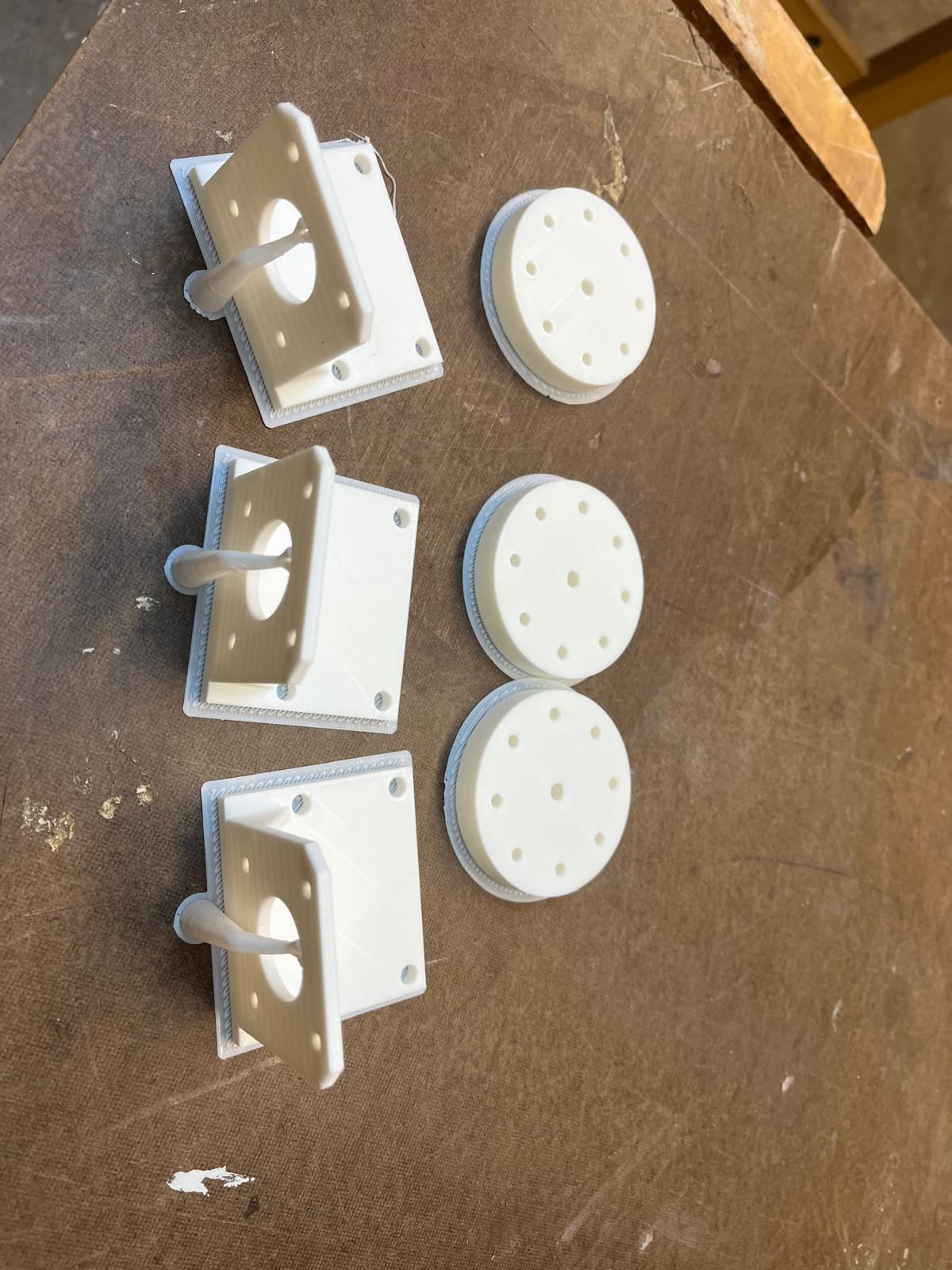
But then I realized that each "wedge" or 6th would take 10+ hrs to print. First, this is a waste of PLA printing material. Second, and most importantly, this significantly reduces my flexibility and TTP (time to prototype). I want a flexbile prototyping process that allows me to iterate designs quickly. So instead, I decided to design each component individually and merge them together using a standard blue recycling bin for the chassis. These are some of the components (shaft <-> wheel couplers and motor brackets) that were produced.
Electronics Design
The data flow here was simple:
- OV2640 camera takes a picture
- ESP32 processes image and runs local CV model
- ESP32 generates bounding box and calculates 3D spacing
- ESP32 sends movement signal to 3x TMC2209 motor drivers
- TMC2209 drivers direct power & signal to NEMA17 motor steppers
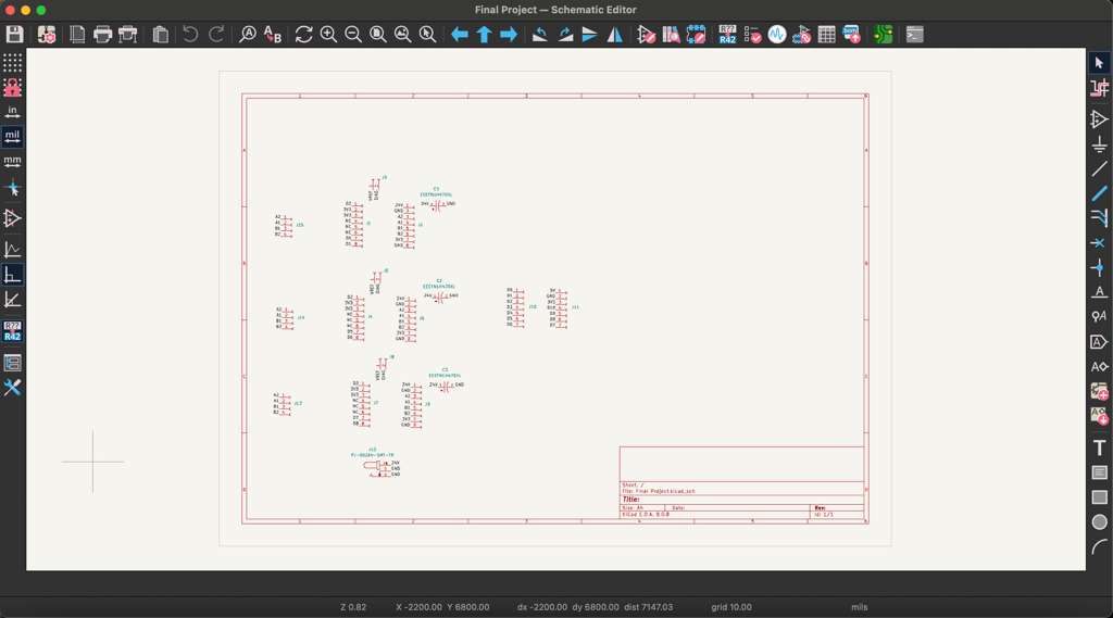
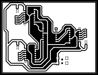
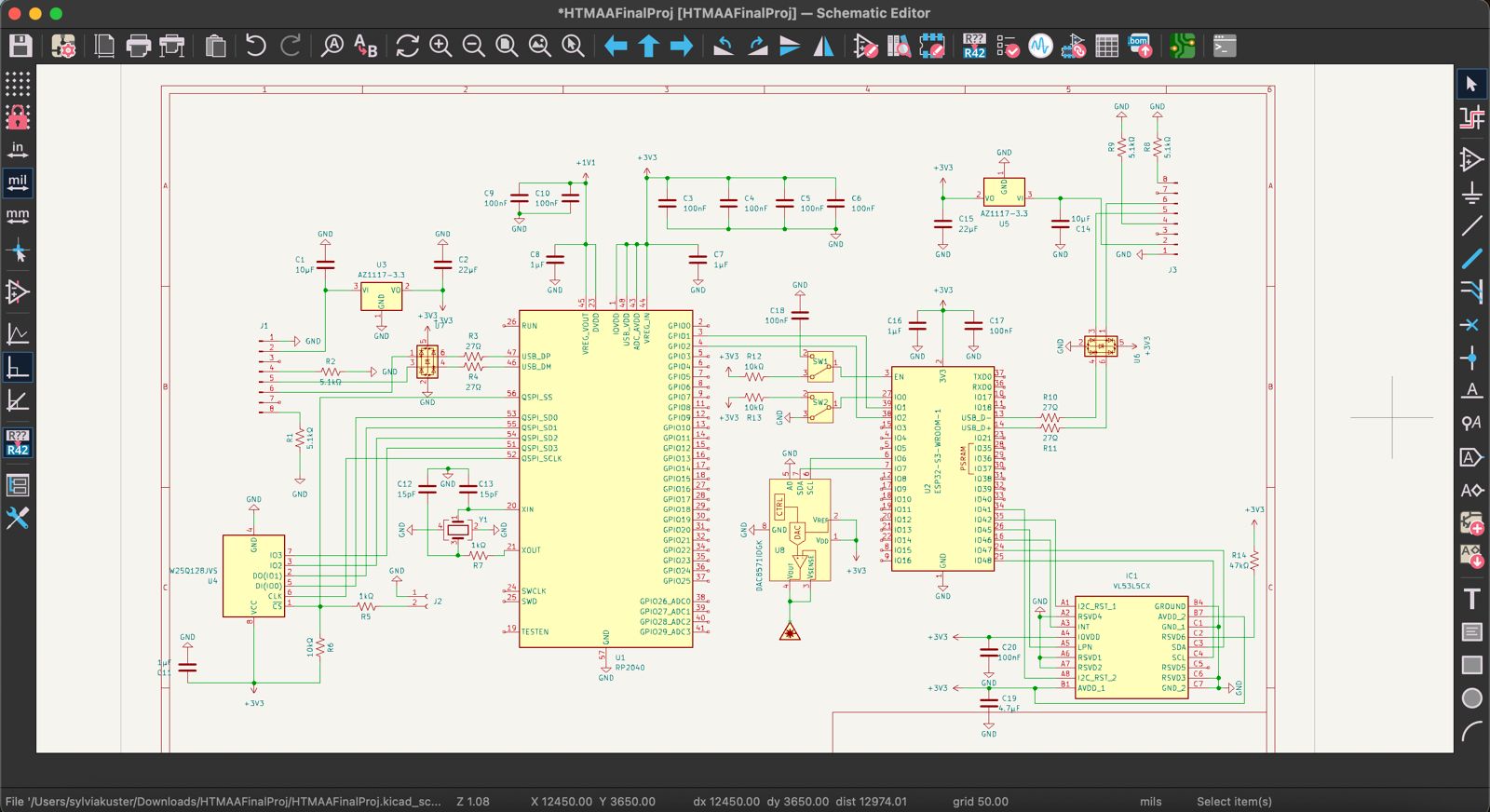
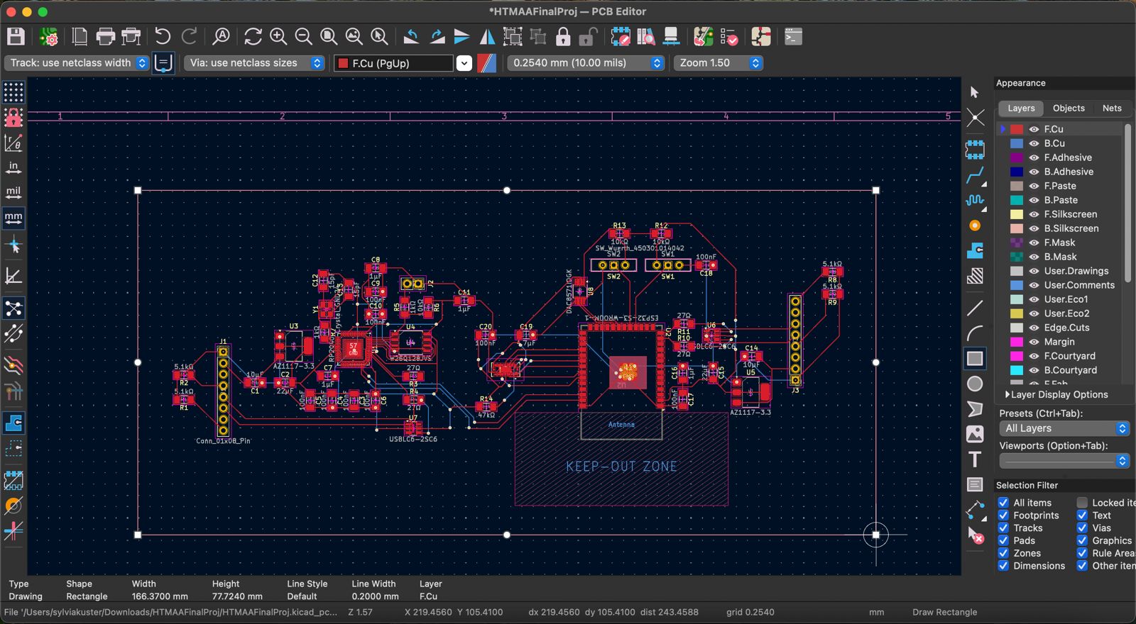
Because of the physical distances these signals had to travel across the trash can, I decided to make a main PCB board to route traces between components. But I soldered physical connector headers / sockets that ran wires through the chassis to reach their destination. This was the best tradeoff between strain / stress relief for the wires but keeping simple localized routing on the PCB. The motor drivers received 12V from a barrel jack connector and the ESP32 logic was powered by an onboard USB power bank. I designed the trace connections on KiCAD and generate .drl and .gerber files (converted to .png) to send to the Modela SRM-20 milling machine. I then soldered the components and crimped all the wires to make the connections.

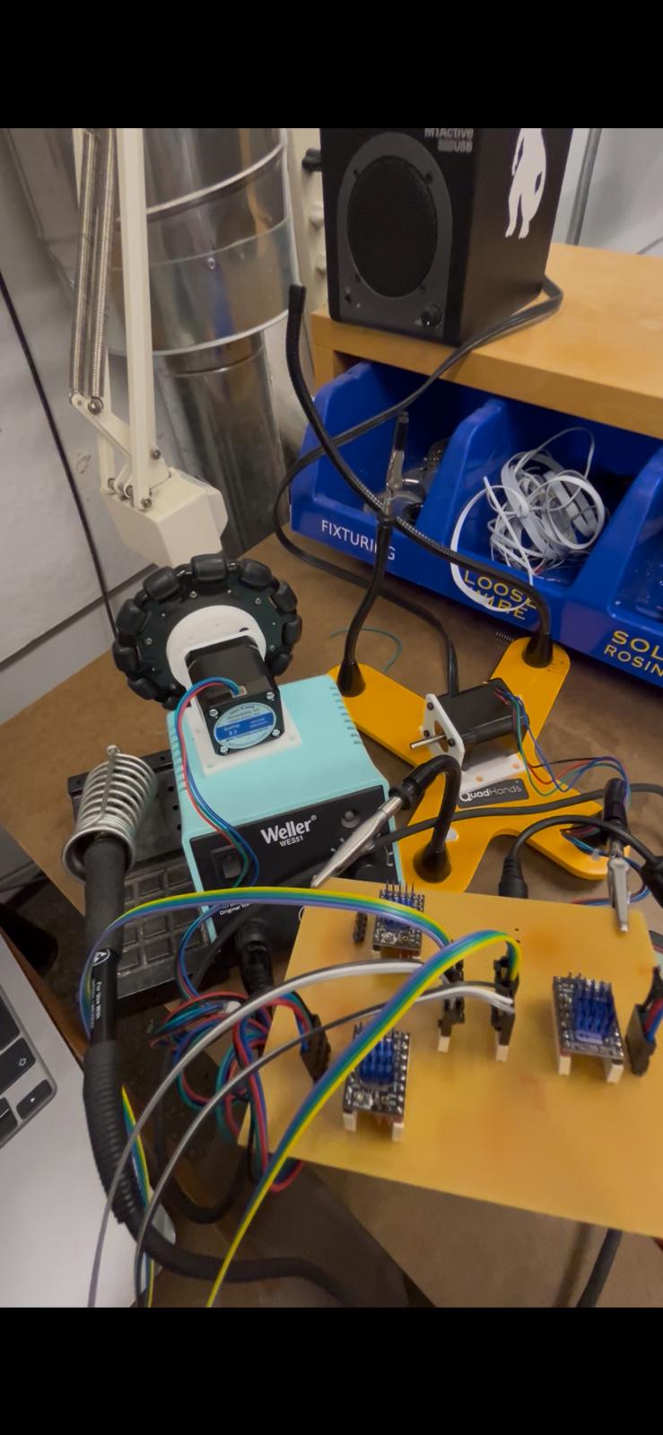
Assembly
Once the mechanics and electronics subsystems were designed and produced, it was time to assemble the physical system. The trash can was screwed into with a power drills for screw holes (M3 & M5) and the rectangle holes for the wheels were cut with an electric reciprocating saw. All wires were routed through and the PCB / power bank were mounted on the sides. The motor brackets held the motor / wheel assembly in place, and a distancer kept tension between the 3x brackets to maintain structural integrity for the flimsy plastic trash can.

Programming
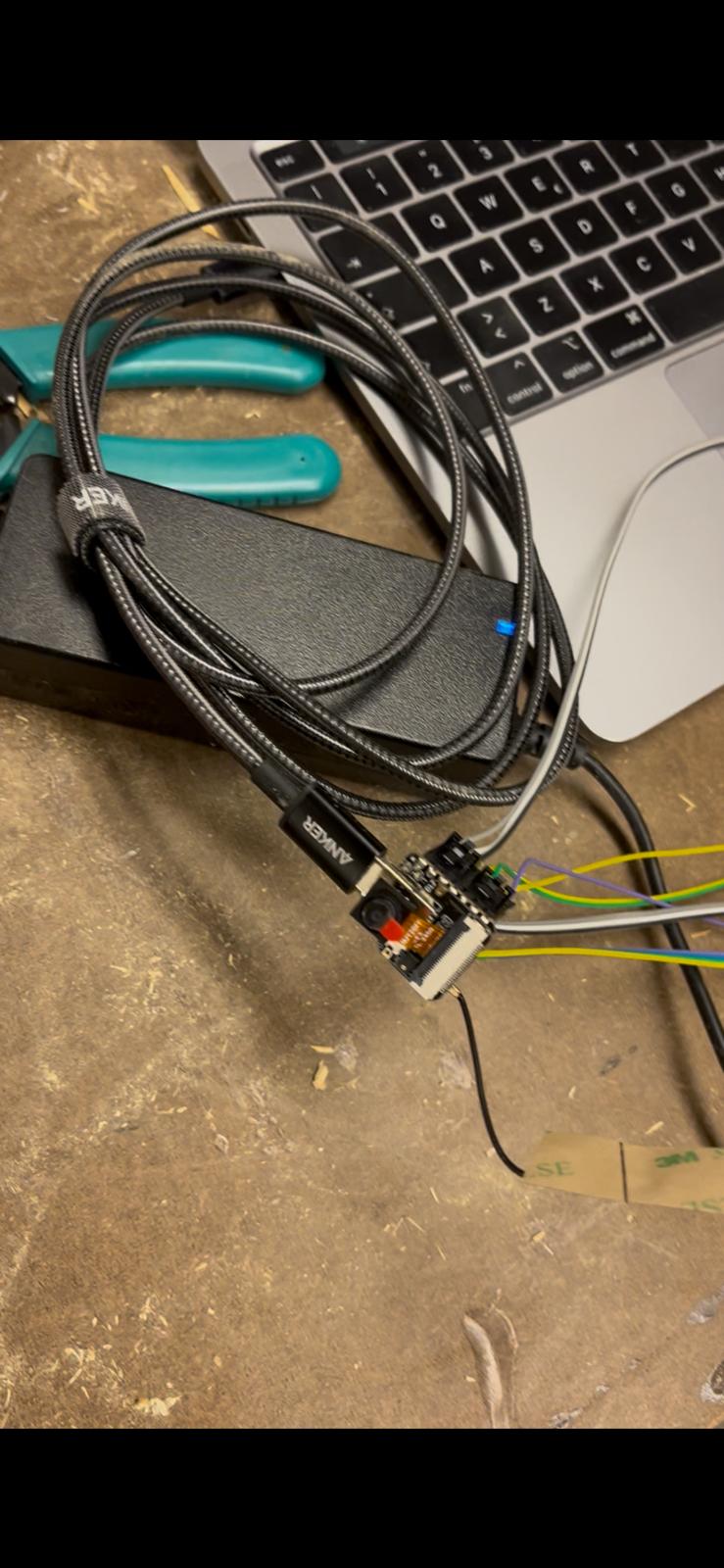
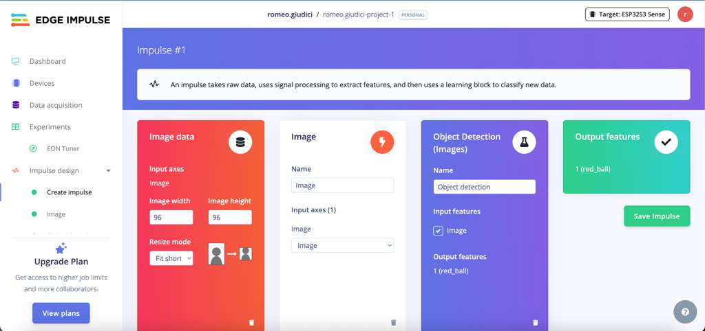
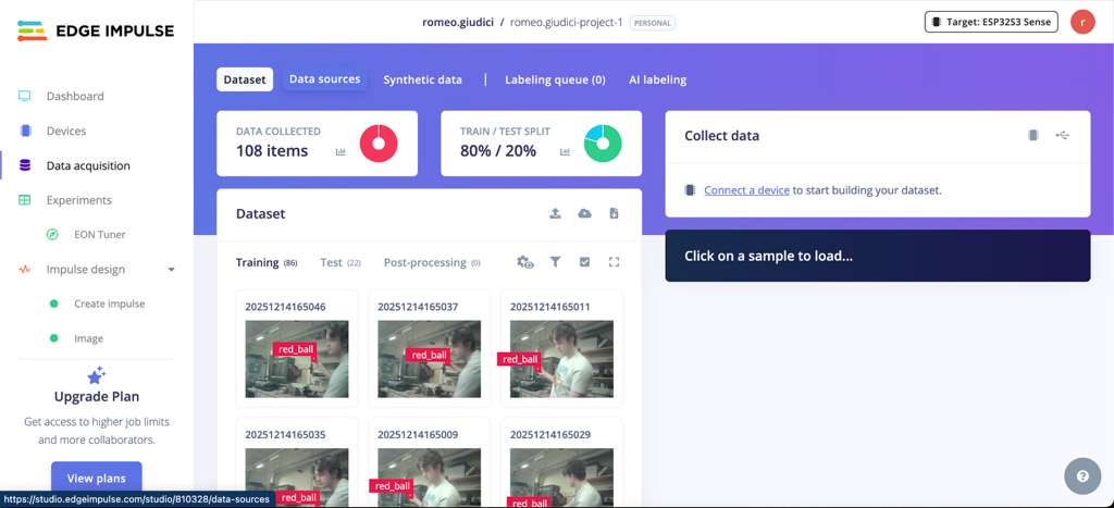
The next part was training a machine vision model to be deployed locally on the ESP32, meaning that it had to be an "edge" model with a smaller dataset, rougher images, and heavily-optimized weights. I connected my ESP32 to my computer via an Arduino script that generated a Wi-Fi broadcast signal my computer could connect to. I then took roughly 100 images remotely on the ESP32 for my training data set. I used the Edge Impulse platform to train my model, first by uploading my dataset and labeling all bounding boxes. I then created an impulse that took a 96x96 pixel RGB value count to run object detection and locate the object in the frame. The next step was using the FOMO (Faster Objects, More Objects) MobileNetV2 0.1 machine learning algorithm for small MCUs like the ESP32 to train the model in the cloud. After completing 60 training cycles, the model was scored on data set aside for testing and scored in the 90%+ range for accuracy. For deployment, Edge Impulse generated an Arduino library (make sure to choose the TensorFlow Lite / quantized 8-bit optimizations) which I added to my Arduino IDE.
The final step was programming the ESP32 logic, remembering the data flow I mentioned earlier:
Take picture -> Generate Bounding Box -> Calculate 3D space -> Send Motor Control
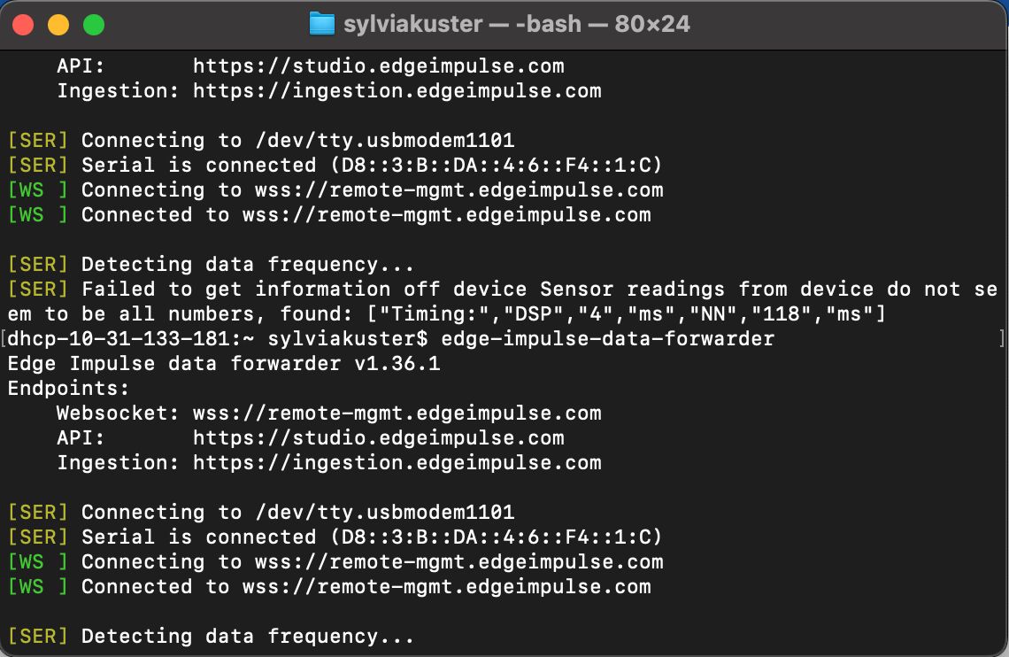
This was easier to achieve when the camera feed and bounding box algorithm was livestreamed to the computer via the Command Line Interface and Edge Impulse Data Forwader over serial. This helped understand the live classificaton process and debug any issues with the model testing.
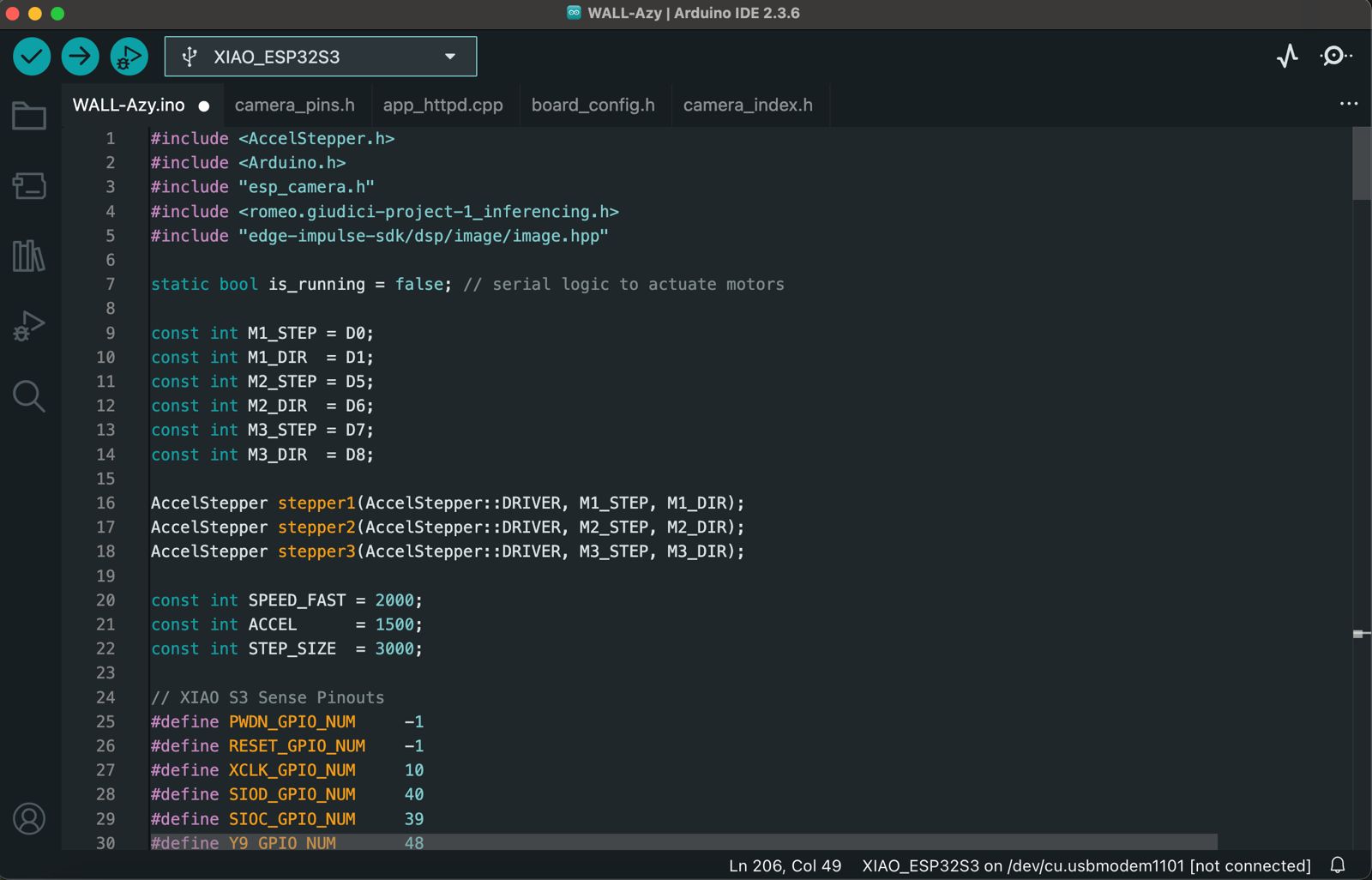
The programming job was mainly an integration of 3 libraries. The first was the ESP32S3 Sense camera configuration, which set the camera pins and initalized the picture sequence. The second was the Edge Impulse ESP32 library with functions that took the image, processed it, and generated the bounding box and confidence score. The third library was AccelStepper to make the stepper motion very smooth once the object had been detected, by creating a gradual increase in speed. Once implemented, this data -> processing -> controls loop took around 200ms for each cycle (150ms+ inference time at 300K peak RAM).
Bill Of Materials
- NEMA17 Stepper Motors - 3x ($30)
- GoBilda Omni-Wheels - 3x ($25)
- ESP32S3 Sense - 1x ($15)
- TMC2209 Drivers - 3x ($15)
- CAP ALUM 100UF 20% 25V SMD - 3x (<$1)
- USB 5V Power Bank - 1x ($10)
- Trash Can - 1x ($Free ;))
- Total: $95
Reflections
That's a wrap on the semester! Quite a cliché, but WOW did it fly by. This class to me is the epitome of MIT - a refreshing reminder of why an education from here is called drinking from a firehose. I am so grateful for all the resources and people I had this semester. It was a tremendous learning curve that has already started helping me in my Mechanical Engineering classes. Overall, I am proud that I reached the goals I set for myself at the beginning of the semester. First, I wanted to get more comfortable with electronics and design at low levels (like making my own 0.1mm trace MCU board during Wildcard Week). The second was building a truly integrated system that blends manufacturing, electronics, and embedded programming. This final project was a ton of fun, a missed night of sleep, and evidence that this class somehow breaks the traditional Depth vs. Breadth tradeoff that everyone else faces, since here I (likely foolishly) feel like I got both.
Final Project Files
Download ESP32 Arduino Code & Edge Impulse / AccelStepper / Seeed Camera Libraries (.zip)Download CAD Components & Full Assembly (.zip)
Download KiCAD Schematic / Footprint / Gerber Files (.zip)
Brainstorming Journal
Here I kept my final project ideas as a journal style, with my most recent reflections at the top. Feel free to give it a look and see how my final project idea shifted over the semester. Hint: A Lot.
Week 10
New week, new final project idea. But I promised myself this will be the last pivot. After a couple months of being inspired by different Instagram Reels projects, I have finally settled on the Auto-Aiming Trash Can. The trash can will recognize trash thrown in the air and move to make the catch. This way everyone could feel like Lebron James and never miss in front of their friends. This trash can would have 2 wheels on the bottom driven by brushless DC motors. There would be a sensing module on top done via either LiDAR (VL53L5CX component) or through computer vision (ESP32 w/ built-in Camera module). The basic electronics circuit would require the ESP32, the Camera module, two drivers controlling the DC motors, and a powerful battery supply. Here is a brief sketch:
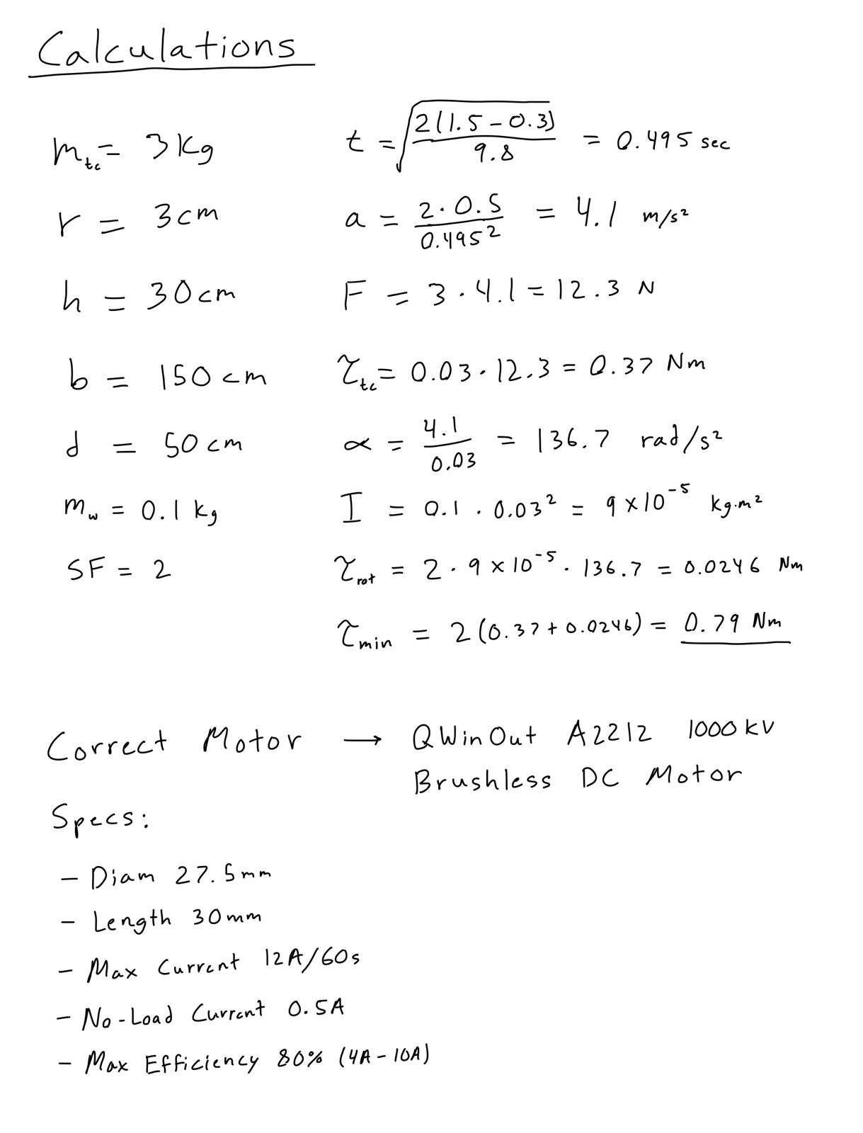
I did some rough calculations for the requirements of the design, which helped me select the motors with enough torque to move the trash can quickly. Key assumptions can change as design progresses but current motor choice is the QWinOut A2212 1000KV, a brushless DC motor for hobbyist drone builders.
This upcoming week will be very busy for me with Machine Week and another significant milestone for 2.009 Product Engineering class. But this is my project plan for now, with tasks and schedule:
- Week 11 - Design and 3D Print the housing for wheels, motors, and power electronics.
- Week 12 (Thanksgiving) - Finalize vision system (LiDAR vs Cameras) and start programming sensing mechanism.
- Week 13 - Assemble trash can, power electronics, wheels and motors.
- Week 14 - Program motor control for trash can movement.
- Week 15 - Final assembly: integrate sensing module with trash can motors. Test, debug, iterate, repeat.
Week 8
This past week I went to office hours and sat down with Anthony to walk through my mosquito project in detail. The biggest takeaway there was that 2 constraints (time & money as always) will not allow me to make a device with such high precision. Therefore, I will be using something more Computer Vision oriented and nerf darts. This update can be found in my Week 8 page.
Week 5
This week I tried my best to start the PCB design for the mosquito laser project. This included a LiDAR emitter sensor module, dual RP2040 - ESP32 MCU pairing, and a hypothetical galvanometer laser system. Find the PCB design process on Week 5 and check out the PCB schematic and layout designs here:
Week 4
I am beginning to lose faith in my garden idea but I have not given up yet. I have just realized there is more bureaucratic red tape than I initially realized. I spoke with our general contractor and they said they would have to open up the wall to create an external water line and electrical socket, which would result in thousands of dollars of work probably. Another factor I had not realized was how long everything takes to grow. Even if I successfully built the gardening system this semester, I would not have anything to show for it and the final stage would not be evident until 5 years down the line. I still think it is my top idea but I have started to think more about backups in case this one fails.
Backup Ideas
- A mosquito / bug / wasp deterrent device that operates like an autonomous laser tracker. This would involve LiDAR sensors that identify mosquitos and bugs with a point cloud algorithm, and a high-powered laser that accurately targets them.
- Remote SOS communication device that works for multiple outdoor sports, that has integrated radio / cellular / satellite systems. This would look similar to an avalanche transceiver but work for a multitude of rescue situations, such as backpacking, boating, and flying.
Week 1
My goals for my final project stemmed from a few core motivations of mine, which I hoped to pursue throughout the semester. My project criteria had to fulfill:
- Fully integrated system involving manufacturing, electronics, and programming to develop skills across engineering disciplines.
- Relevant to the outdoors to deepen my relationship to the natural world.
- Solve a problem / obstacle in one of my communities to improve everyday life.
- Applicable to my family to demonstrate how much their unwavering academic support has enabled me to learn.
- Most importantly: knowledge that I can carry with me after college to pursue in my free time and finally become a maker.
This blend of requirements inspired me to pursue my possible final project: a fully automated gardening system in my front yard.
Through this project, I would 1. build a full stack system involving machining, electronics, and controls software, 2. learn about plants and their biology, 3. improve my neighborhood's charm, 4. collaborate with my parents as they are simulatenously building a garden of their own, and 5. learn how to attempt home improvement projects which I can pursue for a very long time.
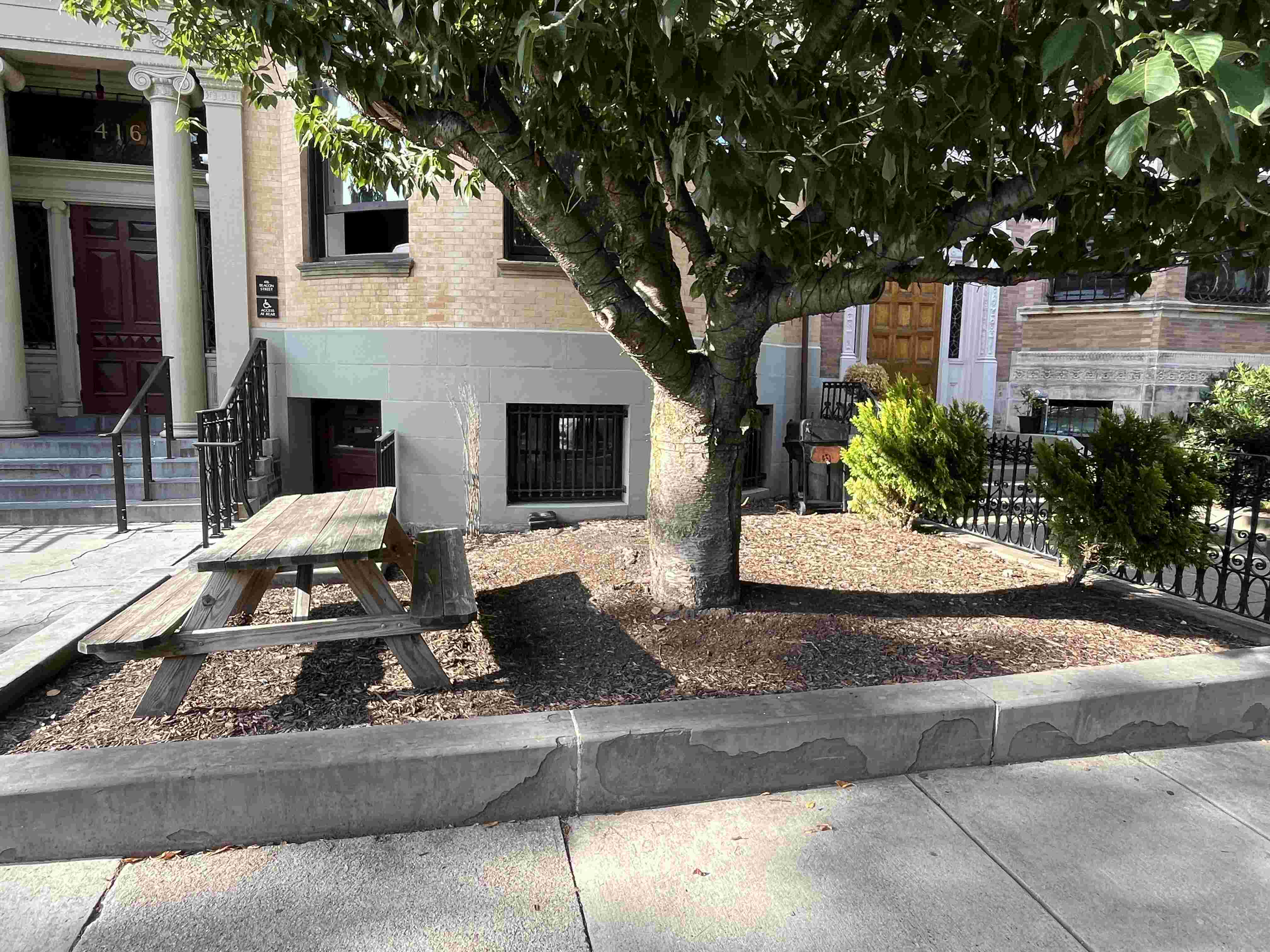
To illustrate how dire the situation was at our front yard, here is a picture showcasing how depressing it currently looks:
Gardening
As a total beginner in gardening, I spent the first part of this project using my good friend Google. The areas I focused on were:
- Perennial vs annual plants
- Ornamental vs crop vegetation
- Boston-area weather patterns including humidity, temperature, rainfall, and sunlight
- Watering requirements for plants
- Vegetation maintenance including fertilizing, trimming, and weeding
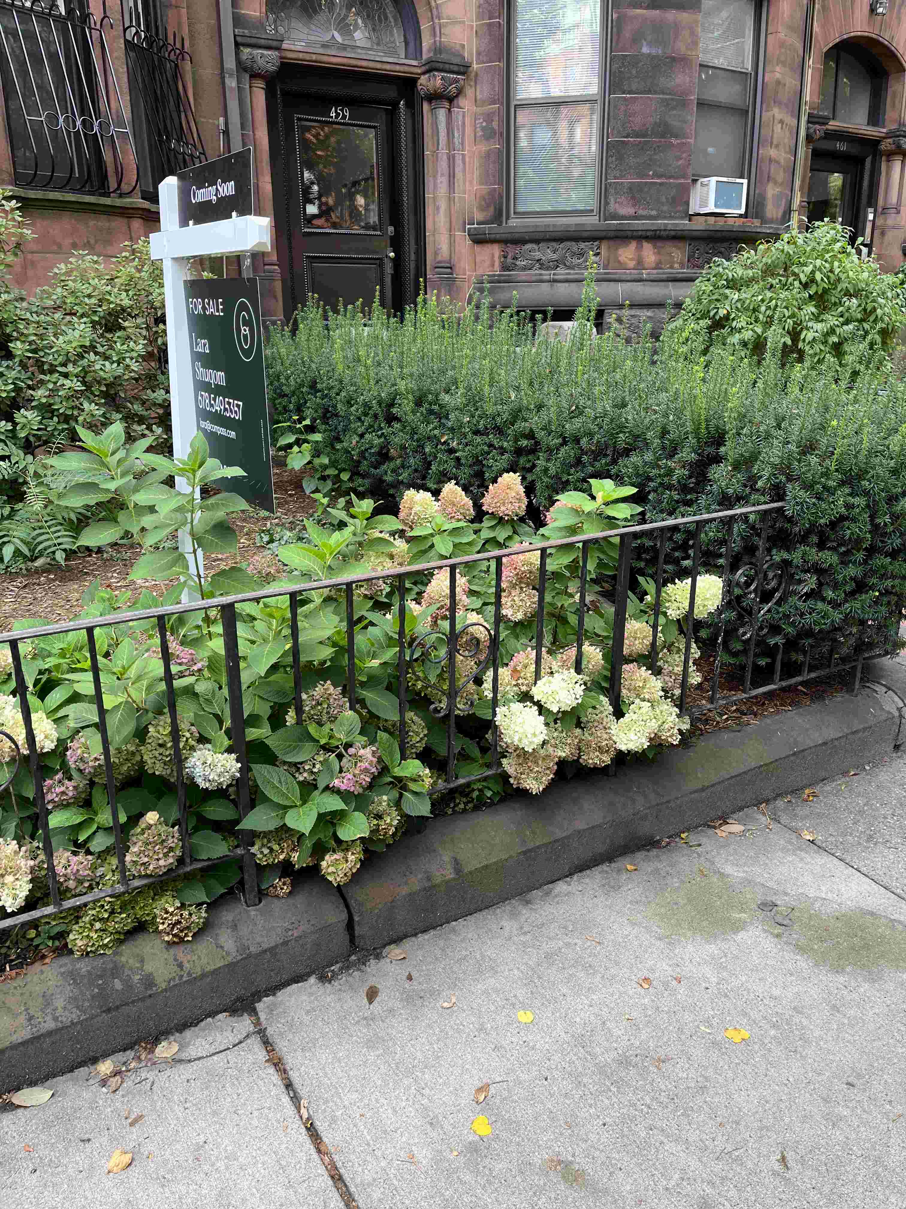
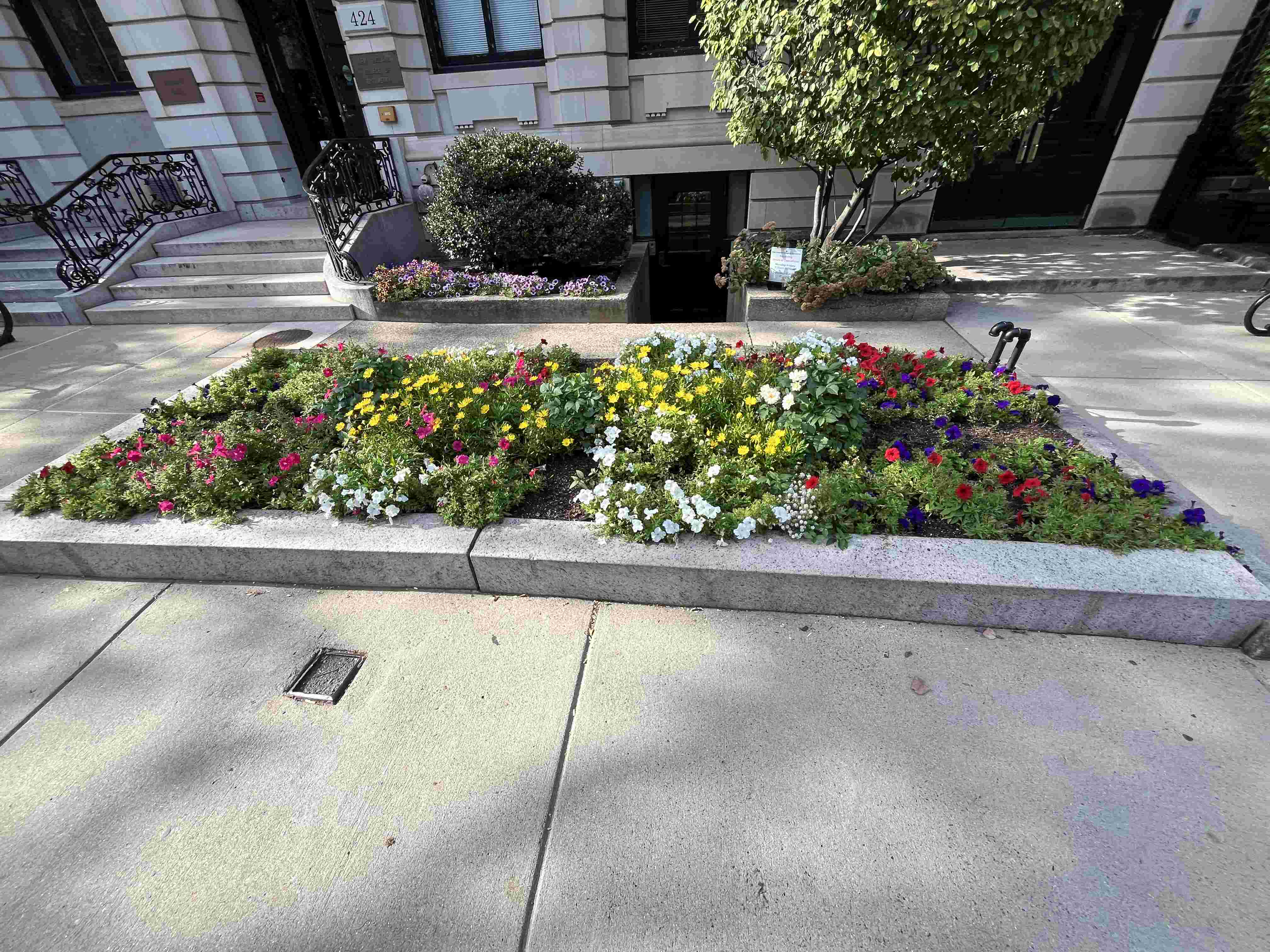
I also decided to undertake more "boots on the ground" detective work by taking a nice walk around the block to draw inspiration from my neighbors. Here are my favorite examples to strive for this semester:
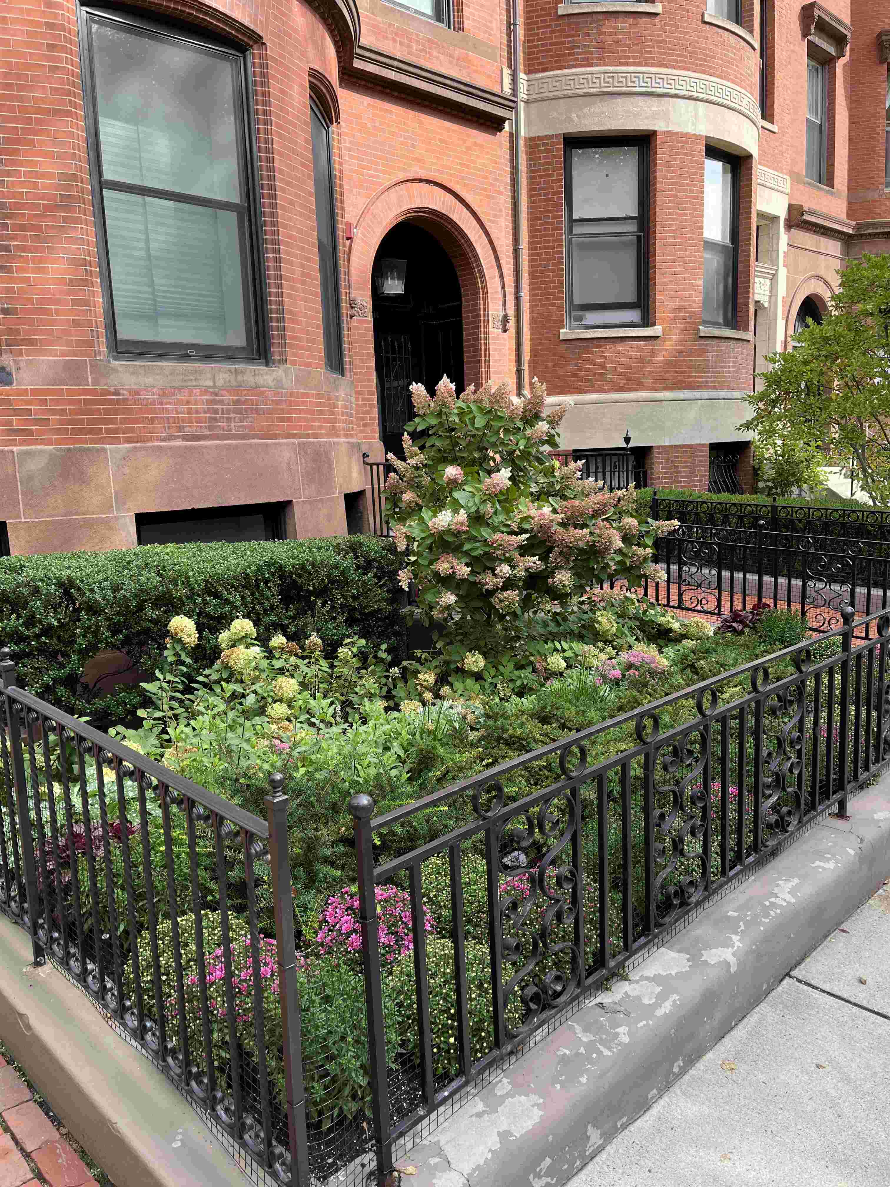
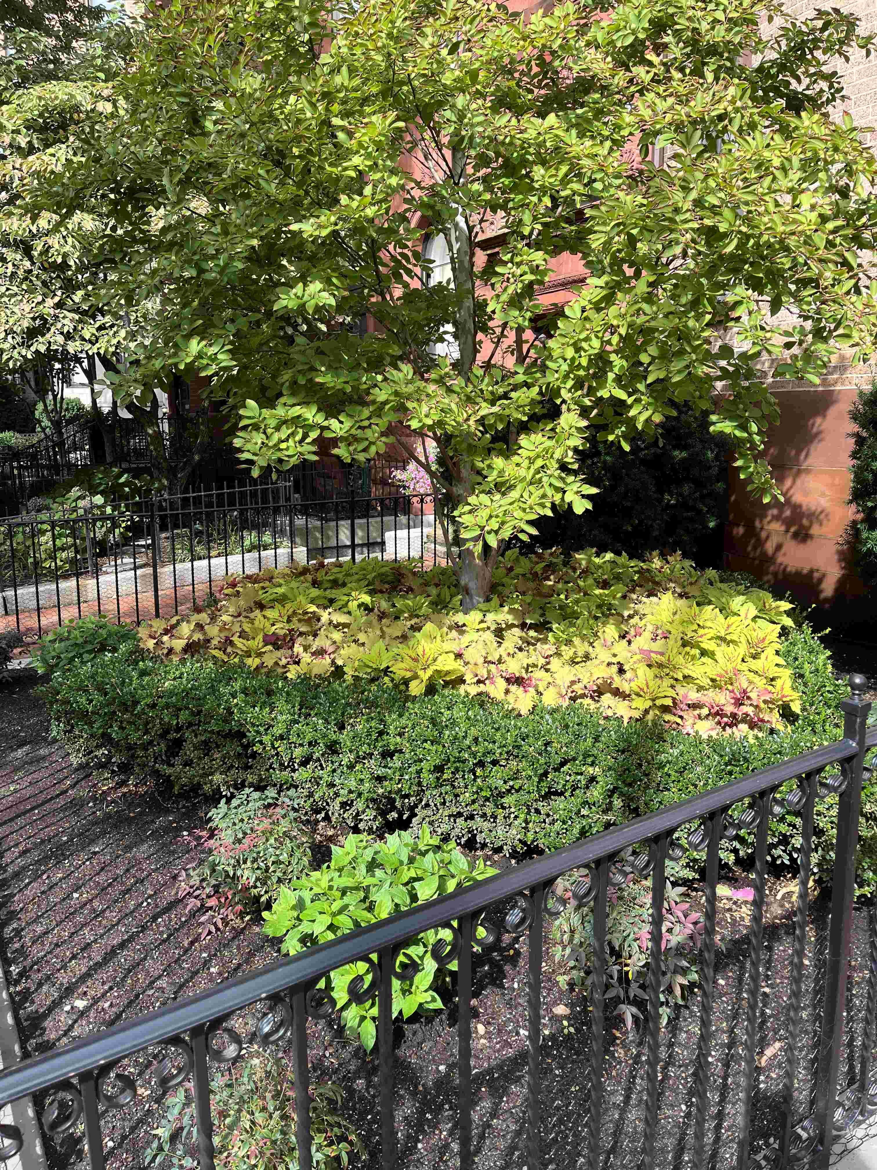
In addition to bushes, trees, and shrubs, I found this arrangement of flowers to be very cool!
Mechanical
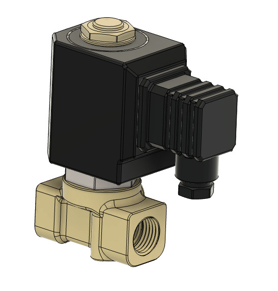
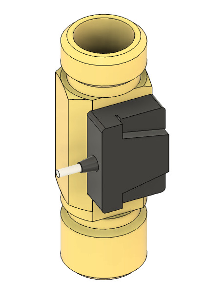
There were many home DIY gardening projects available online to reference. The majority used soaker hose as a method of irrigation attached to the home water supply. Soaker hose consists of a porous material that uniformly releases moisture along its length. The hose is strung along the garden and root beds and activated via a solenoid valve.
Neighbor yards also have ornamental steel fences lining the edge of the garden which I found to be very sleek. Depending on my confidence level with molding, casting, and welding, I could attempt to design a fence around the yard as well.
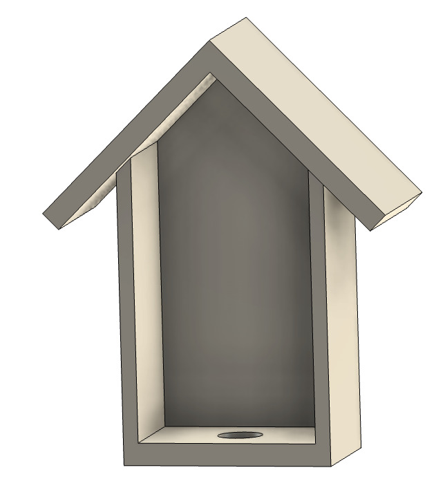
I think adding a bird feeder mechanism would help spruce up the garden and enrich the biodiversity of the area. The wooden feeder could be milled and screwed into the tree. The control panel for electronics could also be added right beneath for protection from rain and snow.
The last mechanical addition I wanted to try was a gravel path in the center that led to the picnic table. This would hopefully reduce foot traffic on the growing plants and add a chic look to the yard.
Electronics & Programming
The core concept of this garden is that it is fully automated and requires limited maintenance, perhaps once a year for some trimming.
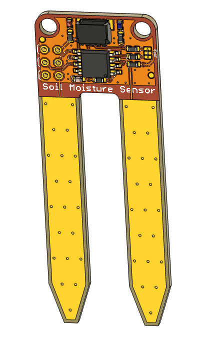
This requires an electronic irrigation mechanism powered by via microcontroller and sensors. Moisture sensors in the soil could provide information on humidity and indicate the microcontroller to open the solenoid valve. This would allow the soaker hose to water the garden at regular intervals and drought periods.
Additional sensors include photoresistors for sunlight detection, temperature sensors, and flow sensors for leak or failure detection. The photoresistors could also be used to turn on string lights hung above the picnic table for when it gets dark. The bird feeder could also have motion sensors to time the dispensing of seeds for wildlife.
The programming logic required could be kept quite simple: when the moisture level falls below a threshold, the valve is opened and the garden is watered for a set interval. Similarly, the lights can come on at a given darkness and the bird feeder could dispense food when motion is recognized.
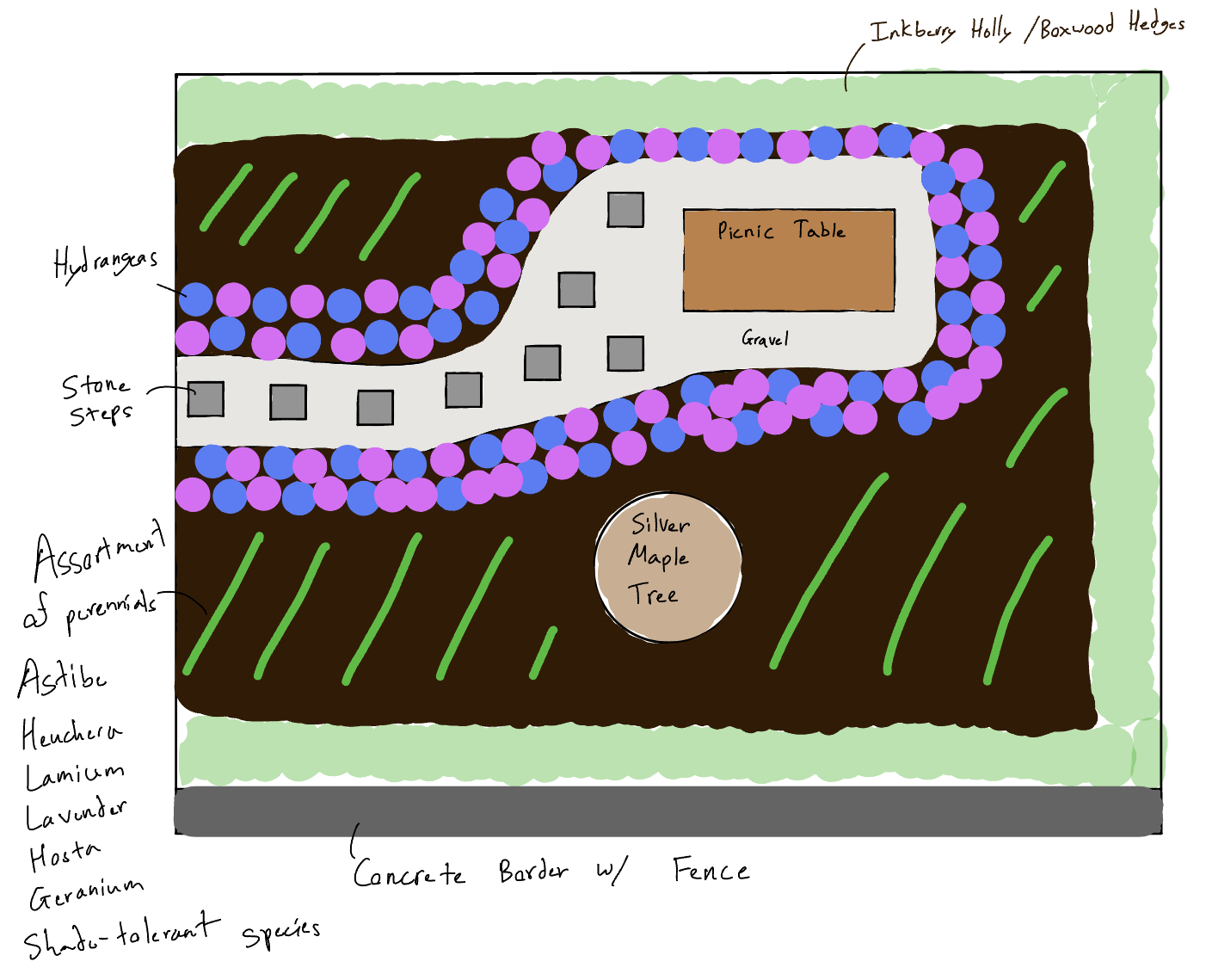
Modeling
I utilized Notability to make a sketch for my planned garden layout. I focused on flower ornaments for the gravel pathway, and strong brushes lining the fence for durability.
Fusion software helped me visualize my bird feeder design and understand the parameters I would have to work with given available sensors. The project did not have extensive CAD potential given the heavier electronics & programming workload.
Summary
I am hoping this garden project comes to fruition (no pun intended :). This would challenge me technically, give me a sense of fulfillment by helping my community, and teach me about nature and plant nourishment. Depending on bureaucratic procedures with contractors / landlords / local government this project could involve more paperwork than desired. I still believe it is worth it and so I really want to give it a shot!