Comparing the toolchains and development workflows for embedded architectures.
Browsing through the data sheet of the microcontroller.
Writing a program for an embedded system with local I/O devices and wired/wireless communications.
Tools
Surface Mount Device (SMD) Soldering
QPad PCB & XIAO RP2040 Microcontroller
Arduino Developer Environment
Individual Assignment
Hardware Components
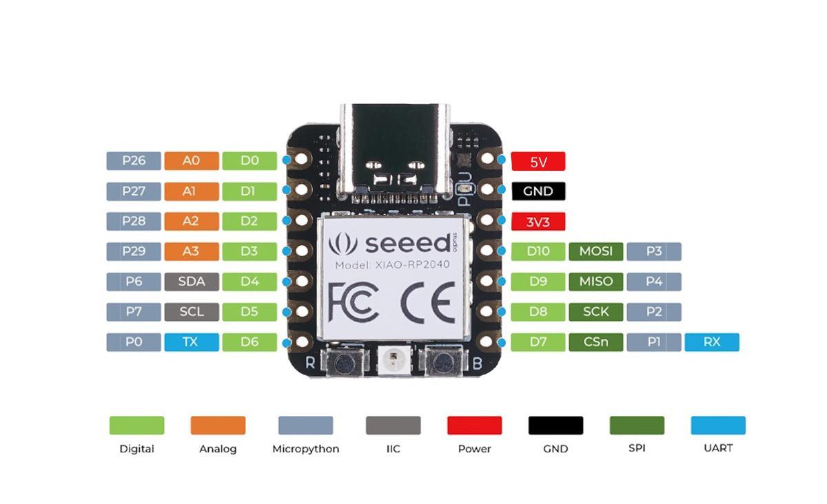
The Microcontroller Unit (MCU) used is the XIAO RP2040 developed by Seeed Studio, a Chinese hardware company. The XIAO is a thumb-sized (20mm x 17.5mm) System-on-Chip (SoC) compatible with Arduino and MicroPython, available at an affordable price for DIY makers. The Raspberry Pi 2040 Chipset utilizes dual Cortex MO+ processors aided by SRAM and Flash memory storage. The MCU interface has 14 GPIO pins consisting of 11 Digital, 4 Analog, and 11 PWM pins along with multiple communication protocols including I2C, SPI, UART. The communication via USB-C can also control Power, User, and RGB LEDs for configuration.
XIAO RP2040 Diagram
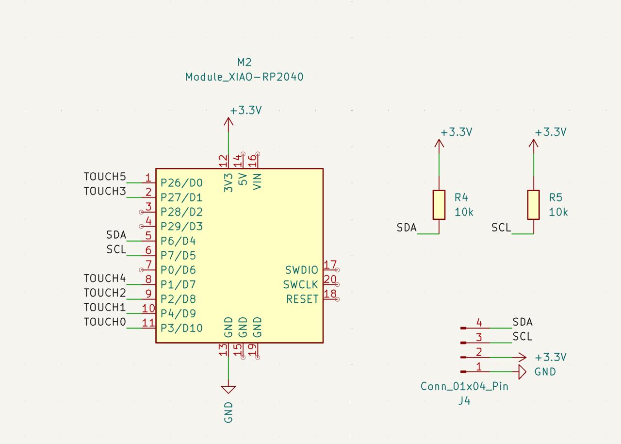
The MCU is surface mount soldered onto a printed circuit board (PCB) ordered by the HTMAA class. The board features capacitive touch sensors that recognize when a finger is placed on top. The KiCad schematic from the TA page show the pin / touch pad pairings. The PCB also comes with a display screen capable of trasmitting desired messages via LEDs.
P03: Touch Pad 0
P04: Touch Pad 1
P02: Touch Pad 2
P27: Touch Pad 3
P01: Touch Pad 4
P26: Touch Pad 5
P06: Display SDA
P07: Display SCL
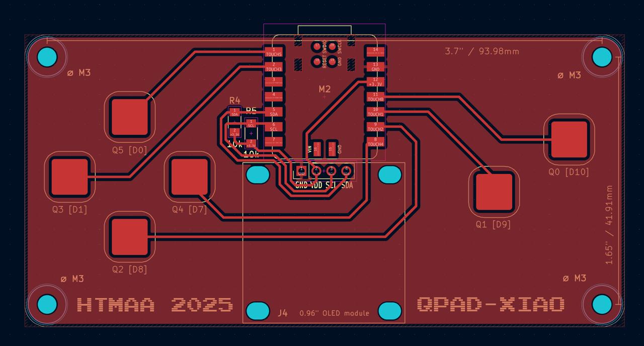
PCB SchematicPCB Assembly
Soldering Assembly
The PCB was assembled by soldering the XIAO microcontroller connections to the copper pads. Due to lab constraints in boards available, the class TA gave me the XIAO microncontroller and corresponding board. Solder paste was spread across the pads and the MCU was placed on top in alignment with the pins. The hot air gun was set to 370 °C and used to dry the solder paste until the moisture was evaporated, leaving behind the molten solder and securing the MCU firmly in place. The hot air paste method demonstrated in the training session was significantly faster than traditional iron methods I have used in the past. As the paste evaporated, the solder left behind stuck to the aligned pins through capillary action, instead of soldering each pin individually as I had done in previous SMD soldering. Additional resistor components were similarly soldered with paste and hot air, while the LED screen was through-hole soldered using the iron.
Soldered MCU Board
Programming
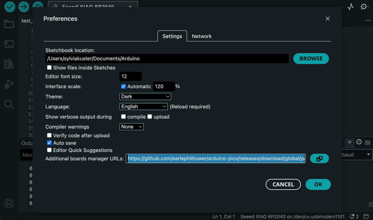
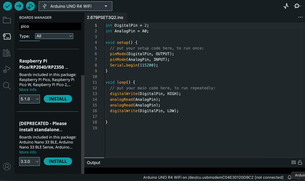
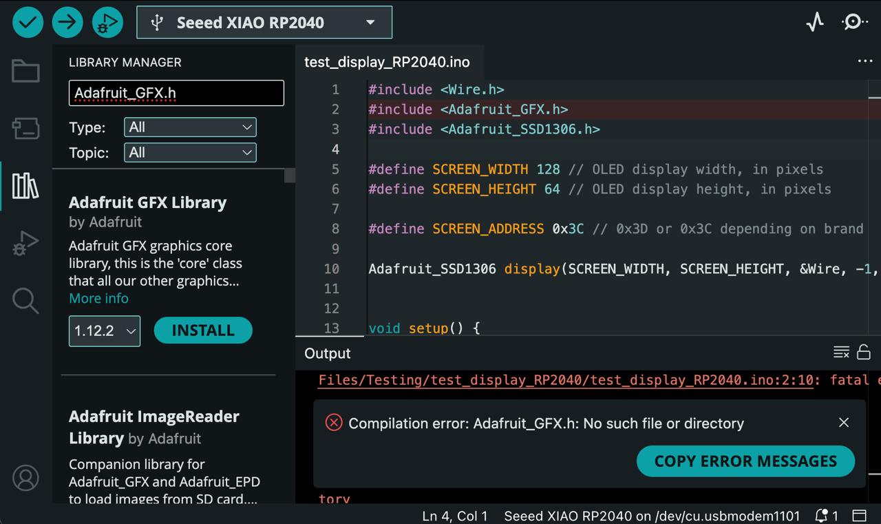
The Arduino IDE can be used to program the XIAO microcontroller, and I already had it downloaded from past projects. To upload code to the XIAO, I had to install the Raspberry Pi Pico board package and add Earle Philhower's Arduino-Pico RP2040 core to the boards manager. Multiple Adafruit libraries also had to be installed to execute code on the board and display screen.
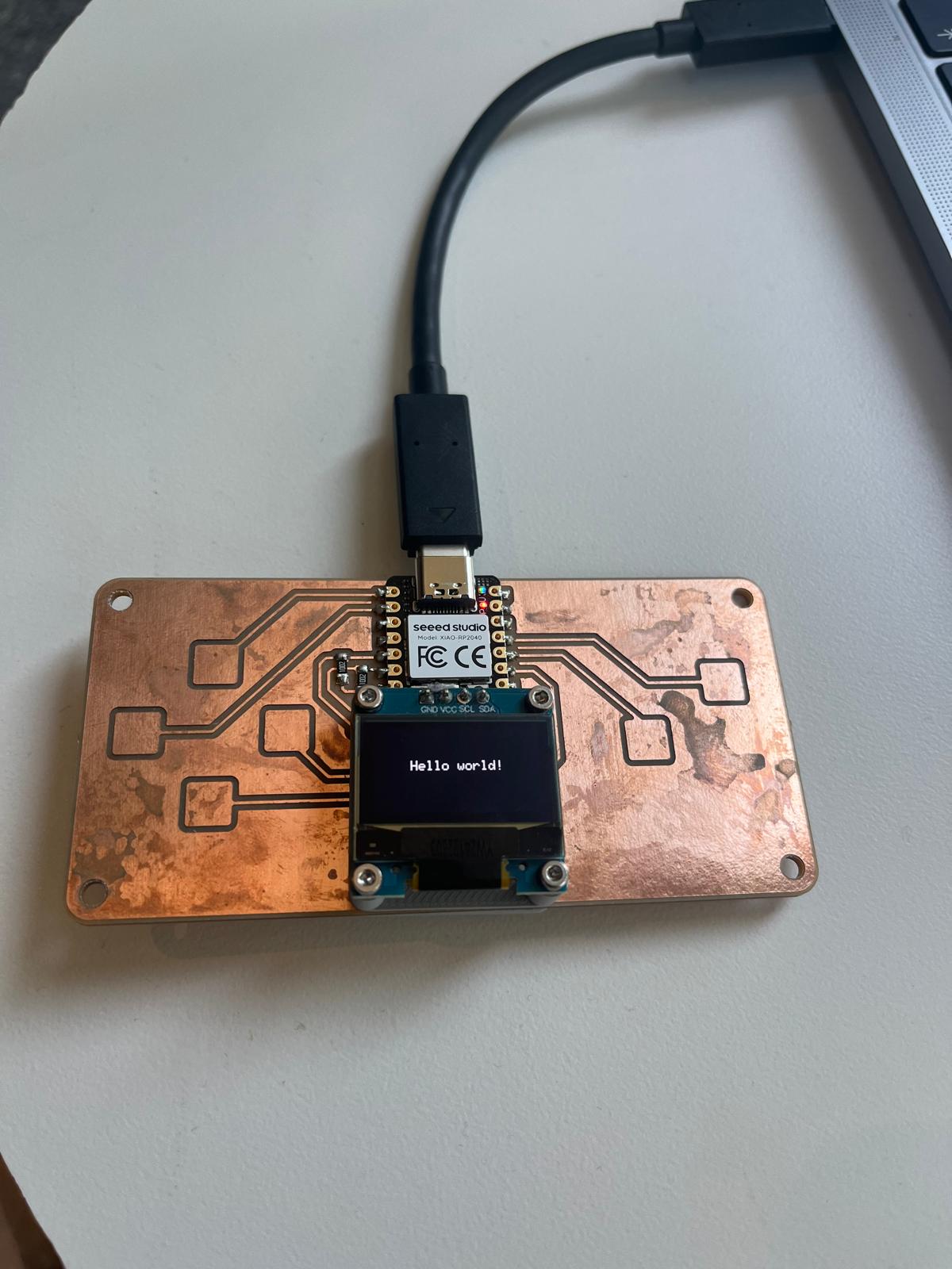
Through the USB-C port connection, code can be uploaded to and executed by the MCU. The example code tests the display function by flashing "Hello world!" on the screen. The serial communication is also tested along with the capacitive touch pads on the PCBs. All 6 touch sensors display the value in a prescribed serial communication column and demonstrated that they are working correctly.
Display Screen Test
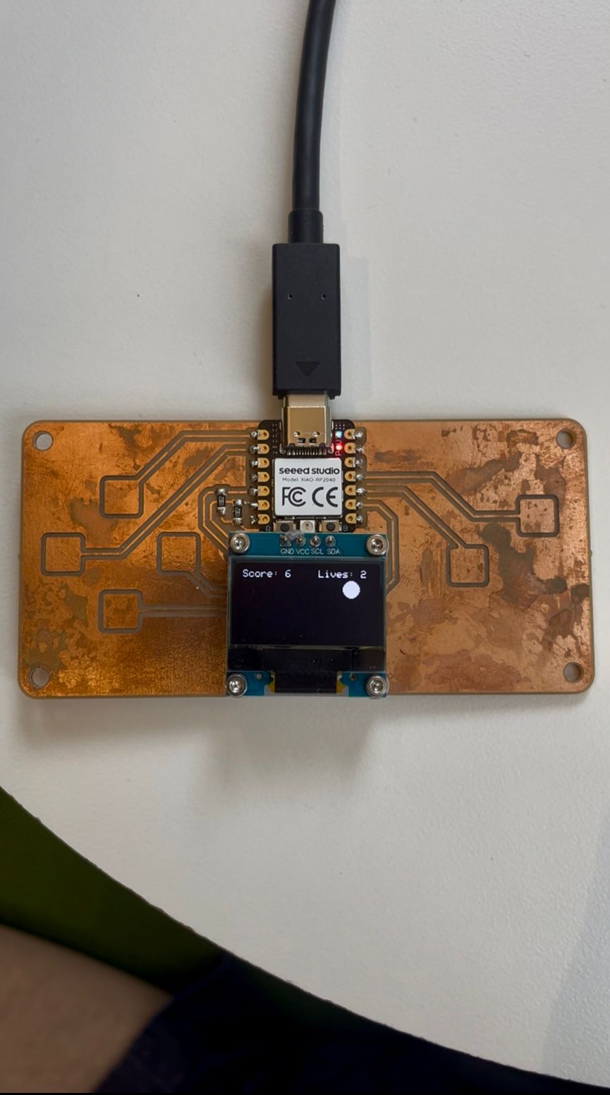
Now that the MCU setup was confirmed to be working, I started to develop a program to display on the screen. I was inspired by Anthony's office hours that showed the T-Rex jumping game found on Chrome when you have no internet connection. In sticking with my theme of the natural world for the semester, I thought it would be fun to add a Whac-A-Mole game (a bit of a stretch I know) to the display and use the touch pads for control. The concept behind this game is that each touch pad corresponds to a different mole position. The player starts with a set number of lives and has to hit the mole that spawns within a certain amount of seconds. If the player whacks the mole by pressing the right pad, a new mole spawns and the score increases by one. If the wrong pad is pressed or the mole timer runs out, a life is taken and a new mole spawns. Once all lives run out, the game is officially over.
I utilized the example test code for the touch pads and display to set up a new program for the Whac-A-Mole game, including libraries for graphics and communication protocol. The Minecraft game example helped me understand how to render graphics via screen buffering, where an image is loaded in a separate, "secret" screen and displayed once ready for a smoother gaming experience. Given the six pads on the board, I added two rows of moles with three in each (a 2x3 mole matrix). The touch pads and the mole display positions were matched with arrays, and it took me a couple iterations to match the right pad with the right mole display. The interface is not perfect because there are four pads on the left side and two on the right side, but I configured it to be as intuitive as possible. For example, when the top right mole on the screen shows up, you have to hitthe top right pad on the board to whack it.
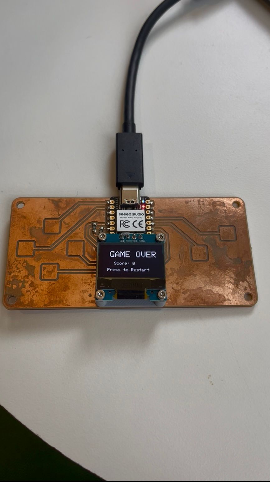
Gameplay DisplayGame Over Display
The game program logic can be separated into three parts:
The first part is the touch pad sensing which is derived from the touch pad test code. The pads are continuously checked for capacitance that results from touching it, and anything above the threshold value of 30 is considered a touch. This way the analog sensor ranging from 0 - 200 can be boiled down to Boolean logic of True or False (eg. touch or not).
The second part is updating the game state based on the user inputs. This checks inputs to start the game and whether the moles have been correctly whacked or not. Based on the user successes or failures, this section updates the scores and lives to reflect the performance and when it is "Game Over".
The third part is rendering graphics, which I mentioned earlier with screen buffering. The graphics package from the display test code was helpful in writing a program that lights up the display for the user. This includes displaying the moles, game over, score, lives, and restart information to the user. The simple display function requires a vector that goes right X pixels and down Y pixels, and then prints the desired text.
I also decided to add extra logic to improve gaming experience, which included a do-while loop that ensures that the newly spawned mole can't be the same as the previous one (eg. no repeat positions). Another addition was speeding up the mole timer as the game progresses, so that it gets harder and harder to stay alive and hit the right button with less time. Outside of the main game loop, the spawnNewMole, resetGame, and update_touch void functions are used to power the game logic. Here is a code snippet for my void spawnNewMole() function:
// defining spawning a new mole function
void spawnNewMole() {
  int previous_mole = active_mole;

  do {
    active_mole = random(N_TOUCH);
  } while (active_mole == previous_mole); // ensures that the new mole picked at random is not the previous mole (no repeats)
  mole_spawn_time = millis(); // resets timer for this new mole

  if (mole_duration > 500) {
    mole_duration -= 25; // decrease mole display time by 25ms per cycle
  }
}
The final configuration of the game was developed by playing with my friends and iterating enough times to optimize the parameters. I settled on an initial 2.5 seconds of mole timer with a steady 25ms decline per mole hit. The starting lives are 5 and the touch pads are configured to the mole position display. The touch sensor threshold is 30 to balance a reactive display without accidentally triggering the wrong pads.
The group assignment was focused on demonstrating and comparing the toolchains and development workflows for available embedded architectures. The architecture section group assignment is available on the section website but I will include my own here.
Microcontrollers
XIAO RP2040 - Works with Arduino (C) and MicroPython
ATSAMD21 - More powerful but requires a bootloader to start
Board Hardware
Micro USB connector — provides 5V input and data for programming/debugging
3.3V regulator + capacitors — converts 5V to 3.3V with power conditioning