Machine and test an embedded microcontroller system that you designed.
Characterize the design rules for in-house PCB production process.
Submit a PCB design to a board house.
Tools
KiCad EDA
Component Search Engine
Modela CNC Mill
Soldering Equipment
Individual Assignment
PCB Design
The week's assignment began by redesigning a PCB. Last week's rabbit hole that started by selectin a tiny processor package for the RP2040 led me to designing a PCB that was according to our class TA Anthony: "the board won't be impossible to mill but it sure is close to that." I could not have milled it on the Architecture shop machine that we were trained on this week, so I instead designed a simpler circuit.
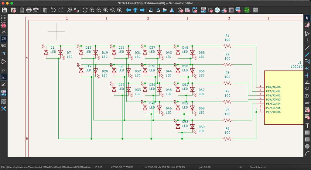
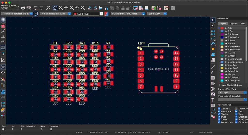
I started a new project in KiCad and decided on a charlieplexing LED circuit. The idea was mentioned by Prof. Neil in class and piqued my interest: with N pins, N * (N - 1) LEDs can be controlled. For each combination of two pins, two LEDs are connected between them with flipped orientation. For example, the anode of one LED and the cathode of the other LED are connected to Pin 1, while the other legs are connected to Pin 2. I added the 3 component schematics: the XIAO RP2040 package (which is millable), 100Ω resistors, and LEDs. I started by ambitiously placing 30 LEDs into the schematic, and then updated the PCB editor to realize that might be overkill. I went back to the schematic and limited myself to 12 LEDs using 4 pins (4 * 3 = 12).
30 LED Schematic30 LED Editor12 LED Schematic
The wiring also presented an interesting challenge. I wanted to design a circuit that did not require any copper traces on the bottom layer, as this would make the milling more time-consuming. However, wiring 12 LEDs, 4 resistors, and 4 MCU pins together without overlap is quite a challenge. This is where graph theory comes in, a very cool branch of math which studies networks with nodes and edges. For a given set of vertices (LEDs), there is a maximum amount of edges (traces) you can layout without overlap. This is called a planar graph, and it follows a simple rule derived from one of Euler's formulas: E ≤ 3V - 6. To double check, we have 4 pins and 12 LEDs which translates into 4 vertices and 6 edges. This satisfies the inequality as 6 ≤ 6.
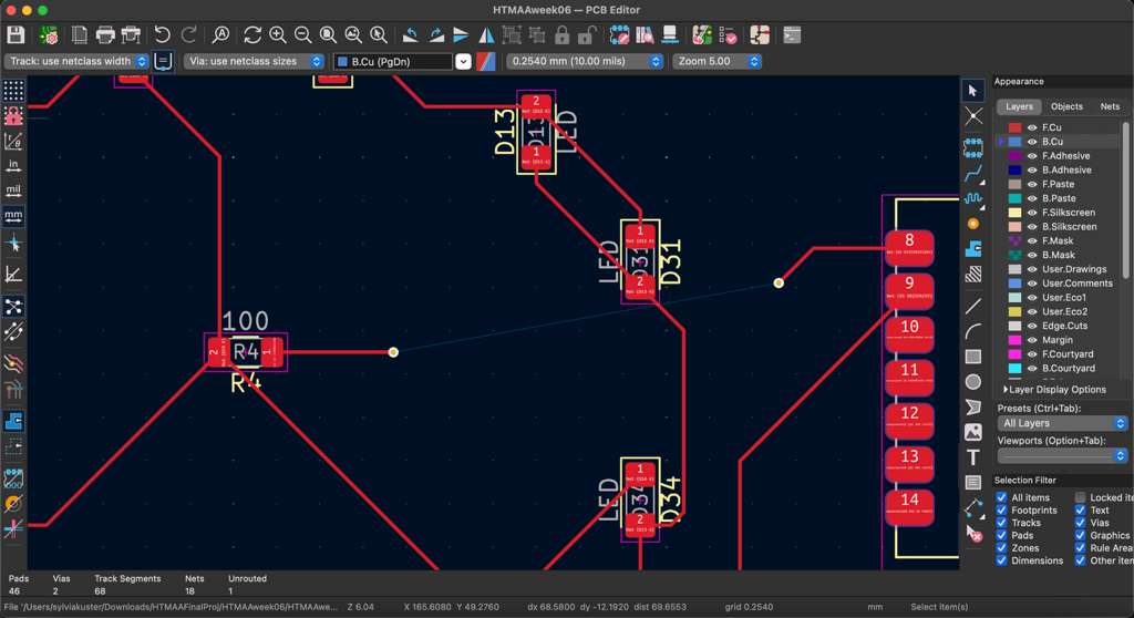
I started arranging the LEDs around the MCU in the center. After a couple iterations, I realized something was not working out right and 1 traces needed to overlap. I did some research and tried to follow the optimal design by placing the MCU to the side and creating a triangle with 3 resistors, with the fourth in the center. Following a couple attempts, I realized my foolish graph theory plan would not work since I miscounted the number of edges by not accounting the connections to the MCU. There was also going to be 1 single overlap required, so I decided to lay down two vias in the design (just in case) and work something out with jumper wires later.
Center MCU LayoutSide MCU LayoutVia Connection
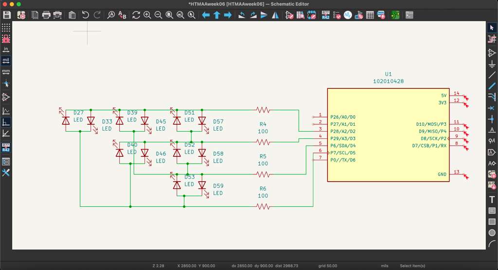
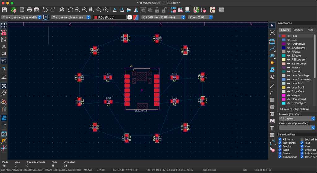
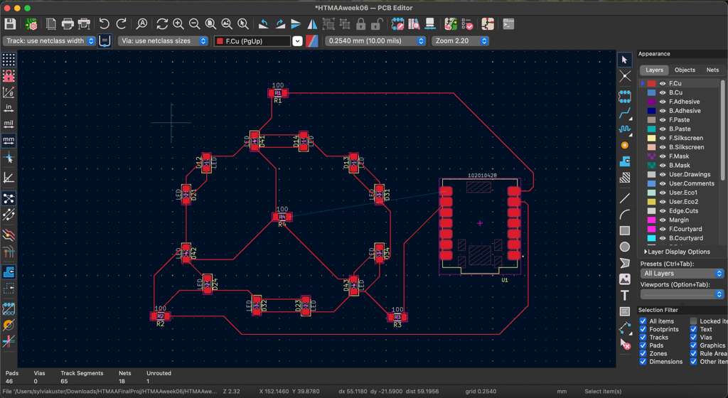
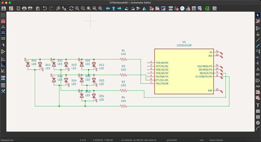
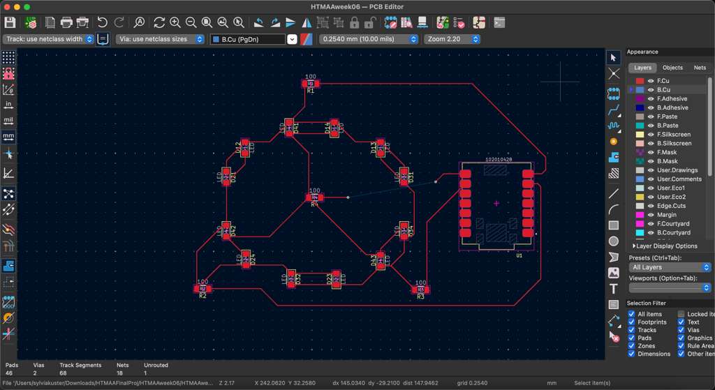
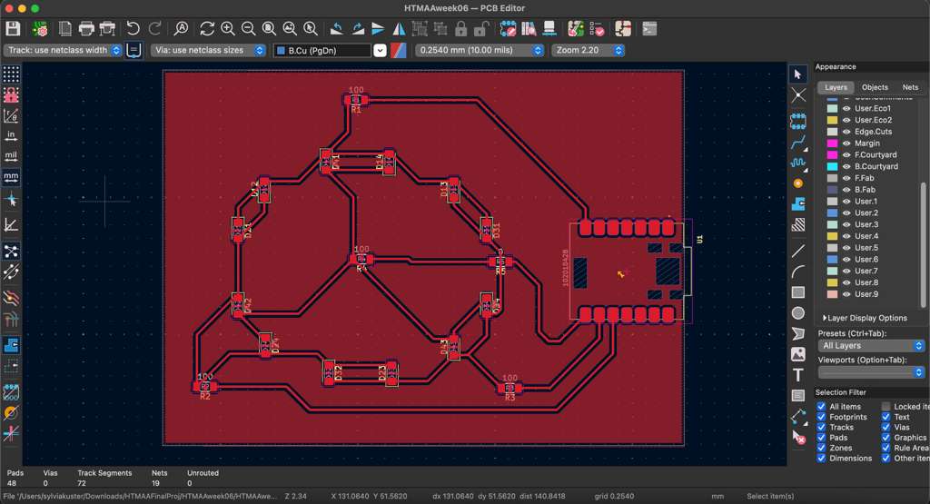
I finalized the PCB layout and edited the schematic to connect to more conveniently placed pins on the MCU. These are the final schematic and layout designs:
PCB SchematicPCB Layout
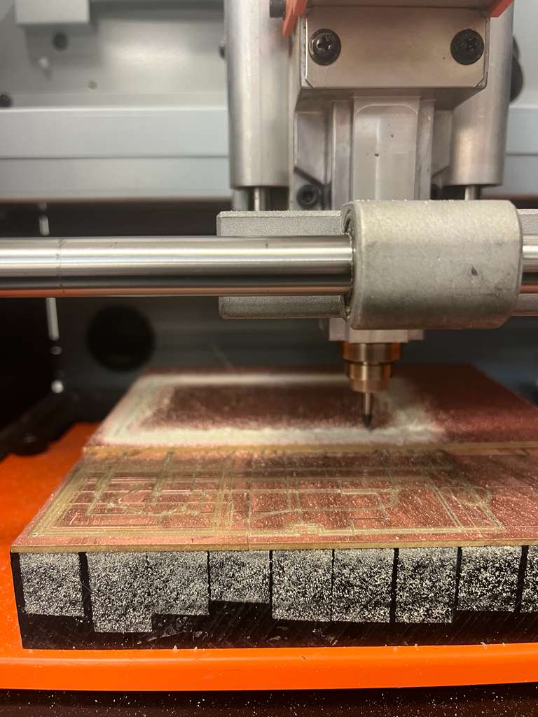
PCB Milling
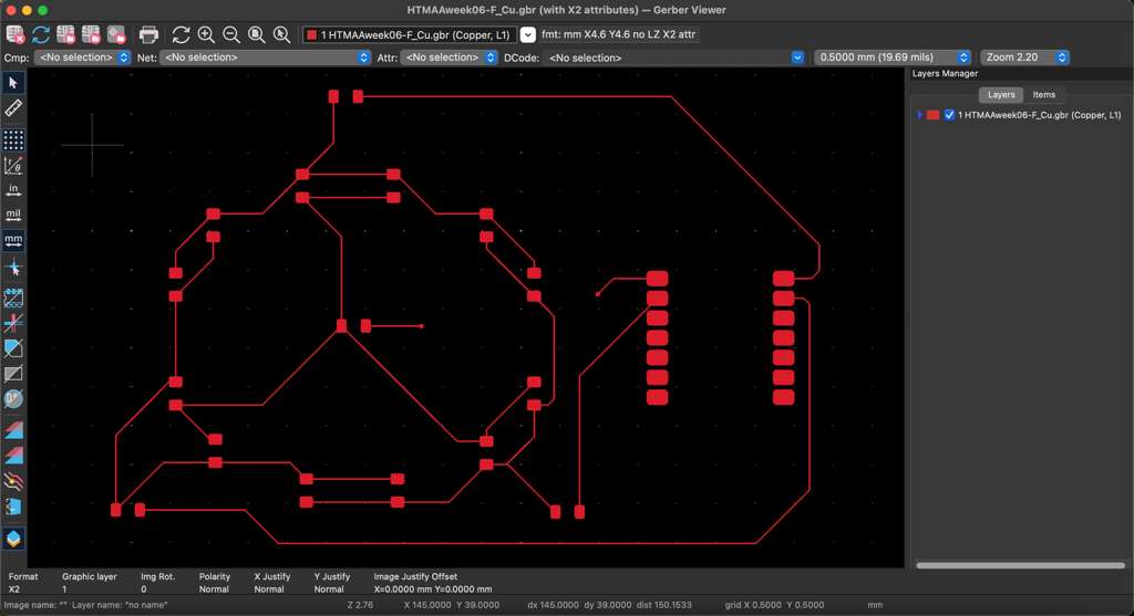
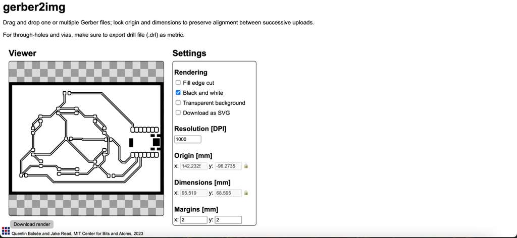
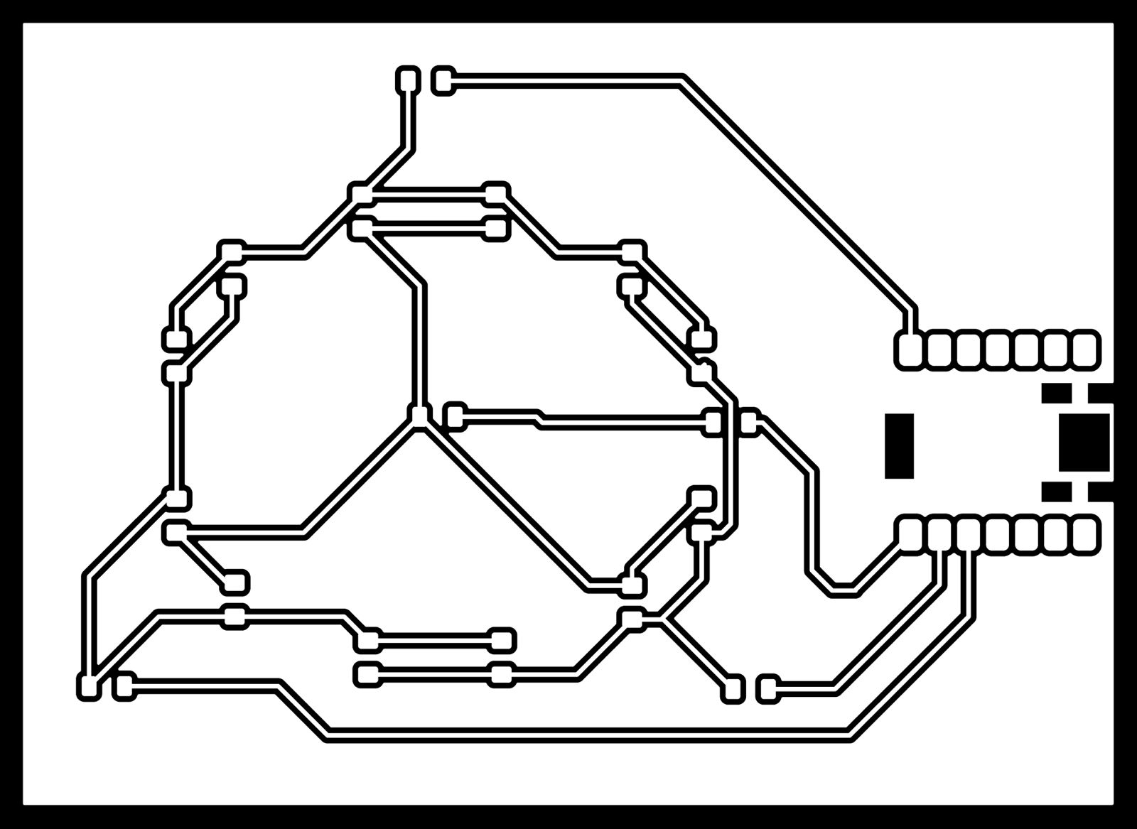
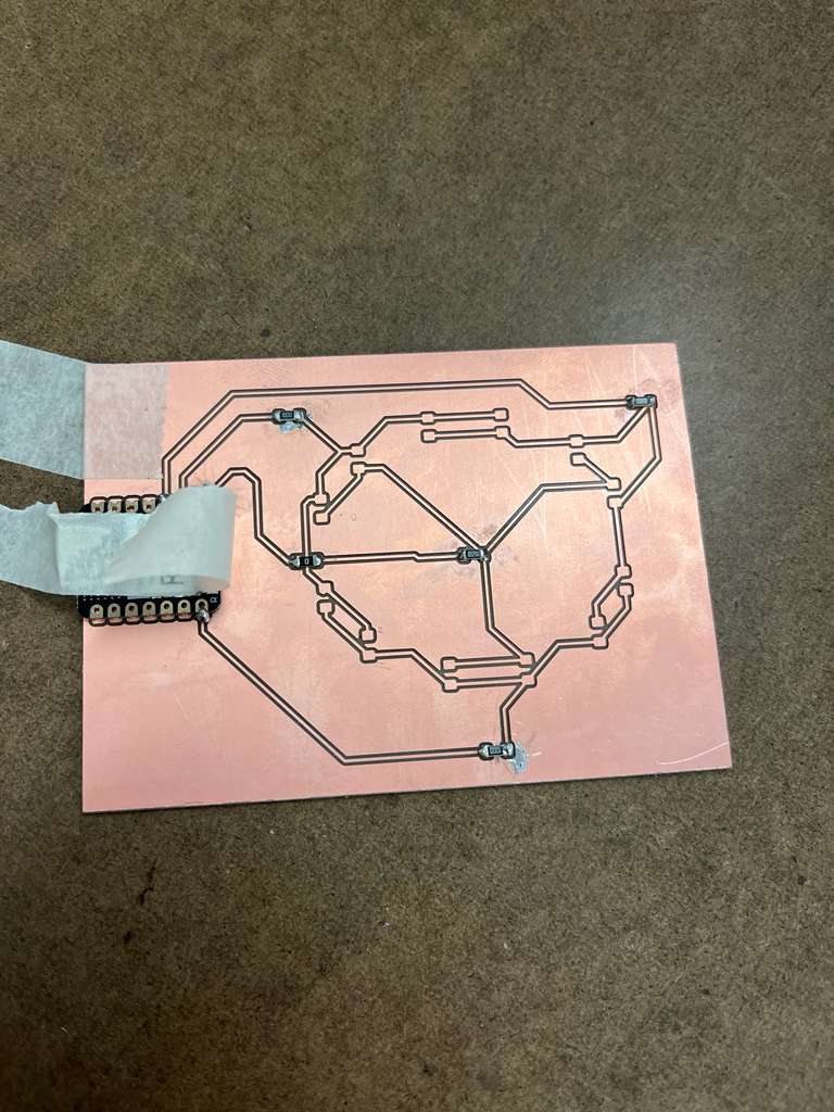
After my design was complete, I headed to the Architecture shop to start milling my PCB on the Modela SRM milling machine. This machine uses a 1/64" end mill to cut out copper traces from a board for homemade PCB design. The machine uses shop software (Mods) which is similar to the vinyl cutter. To begin, I exported my design in KiCad to Gerber files for the top layer and the edge cut. It is important to fill the board outline using the Filled Zone tool: my initial mistake had incorrect outlines and could not be milled. I went back to KiCad to redesign the board and also point the XIAO outside to better plug into the USB-C port. Once exported as Gerber files, I used Quentin's gerber2img converter to create a .png file for the mods software.
Incorrect GerberFixed DesignGerber2img Converter
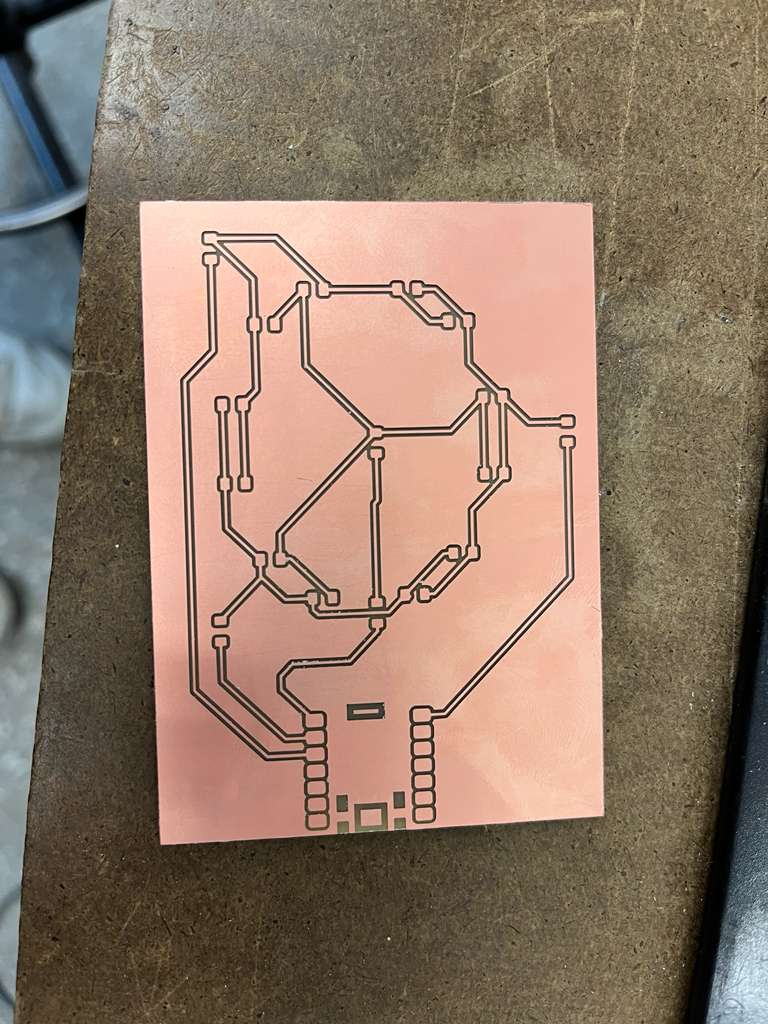
I imported the .png files into the mods software and established connection to the Modela machine via the terminal commands. The mods software was then used to create a toolpath for the machine to cut the copper board. I placed a new copper sheet on top of the spoilboard with double-sided tape, double-checking that it was on smoothly. Then, I used the hex bar to loosen the collet and insert the 1/64" endmill and calibrated the XY origin. To set the Z origin, I unscrewed the collet ring again and pushed the mill tip down into the sheet and screwed it in again. The file was then sent to the machine to begin cutting, which took approximately 30min for the traces and mill outline cut (which was done with the 1/32" end mill).
Tool PathEndmillFinished PCB
Assembly
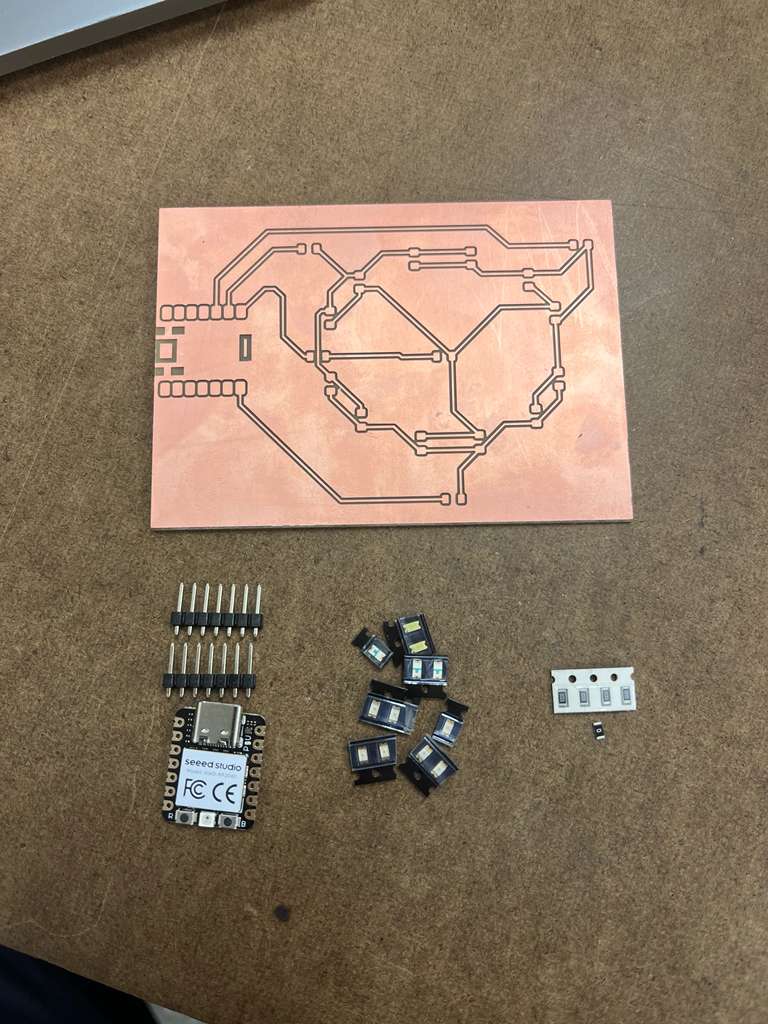
The next step is to assemble the board with a soldering iron and components. The 1206 package is large enough to comfortably solder with an iron without solder paste, which is what I will mainly be using. For the setup, I gathered my components which included:
XIAO RP2040 package
12 SMD LEDs of varying colors
4x 100Ω and 1x 0Ω resistors
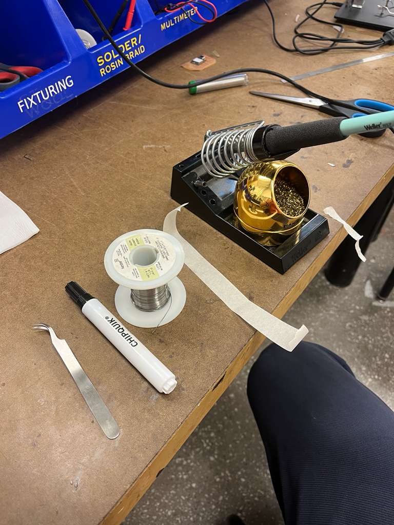
I also gathered all the tools I needed for soldering, consisting of:
Soldering iron
Flux pen
Tweezers
Tape
Solder wire
Light microscope
Once the soldering iron is heated to 700deg Fahrenheit, the soldering procedure is pretty straightforward:
Step 1: Flux is placed liberally on top of the pads.
Step 2: The component is placed on top of the pad and held with tweezers.
Step 3: A small bead of solder is melted on the tip of the iron.
Step 4: The iron then touches both the pad and the component.
Step 5: Remove the iron after 5 seconds and keep the component in place for another 5 seconds.
ComponentsToolsFlux PenSoldering Iron
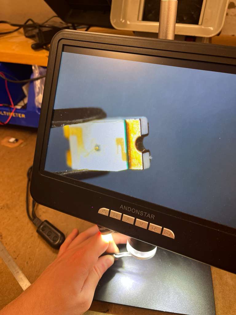
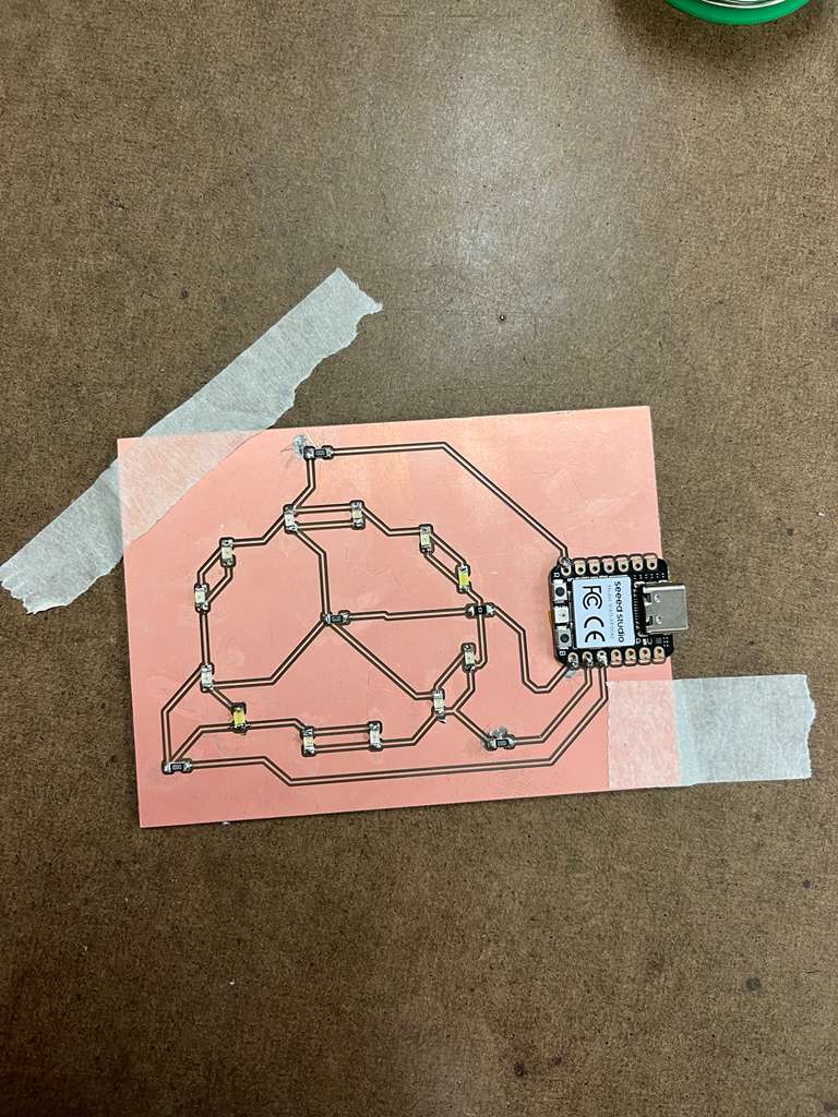
For this board, I started off with the most complex component which was the XIAO. and then soldered the 5 resistors. The LEDs were a bit more complicated because of their polarity in orientation. The LEDs have two pins: the cathode is connected to V-, and the anode is connected to V+. There is a thin green line on the LED to highlight the cathode, which I used the microscope to show clearly. Once the LEDs were soldered on the board, I tested the board with a multimeter and began programming the light show.
Soldered ResistorsLED PolaritySoldered Board
Programming
I assembled a wide variety of LED colors for this board, including Red, Orange, Blue, Green, and White in order to have an exciting LED light show. I started to work on my program and settled on a for loop that iterates through every possible pair of XIAO pin combinations, cycling between on (HIGH), off (LOW), and disconnected (INPUT). These three pin controls give the circuit the ability to vary through power combinations and light up all 12 LEDs with only 4 pins. Once the program was complete and the right XIAO pins were mapped, I uploaded the code to the MCU and watched the magic begin!