Design, mill, and assemble something big (~meter-scale).
Test runout, alignment, fixturing, speeds, feeds, materials, and toolpaths for the machine.
Complete lab safety training for appropriate machine use.
Tools
Fusion (CAD & CAM)
Mastercam Software
Onsrud 3-axis CNC Mill
Bandsaw, Sander, & Circular Saw
Individual Assignment
Ideation
This is Make Something Big week! The assignment is to mill a meter-scale design without the use of fasteners (glue, screws, nails, etc). In line with my goal to focus on the natural world with weekly projects, I wanted to try to design a wine barrel. Luckily, both of my parents happened to be sommeliers who explained the art of coopering. Traditional barrel-making techniques use special wood that is aged outside for years, before using steam and flames to bend the material into the iconic barrel shape. Given the assignment limitations (I don't have time to age wood for three years outside, and we are using low quality OSB), I doubt my barrel will successfully hold liquid. I still want to give it a shot and at least assemble something that resembles a barrel shape. During the lab safety training, I cut out a 6in x 40in plank of OSB wood to test the flexibility of the material. The lab instructor Chris suggested soaking the plank overnight to minimize the splintering that happens under shear stress.
Design
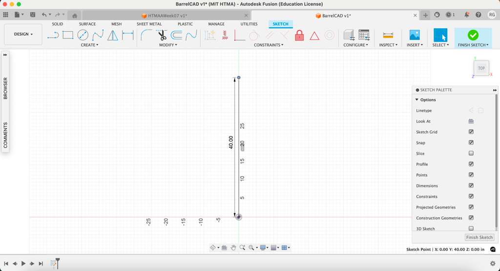
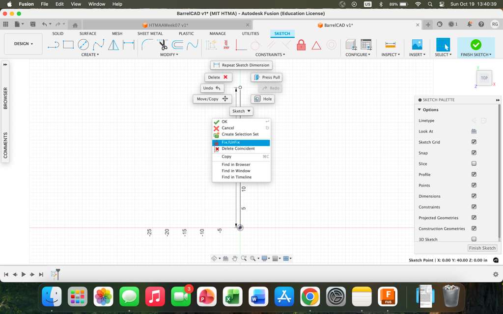
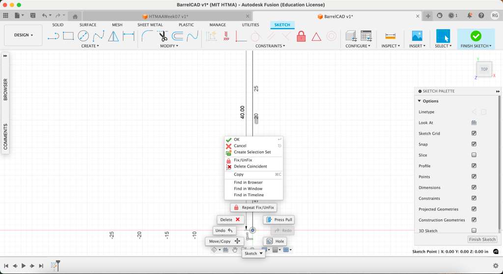
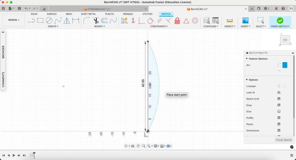
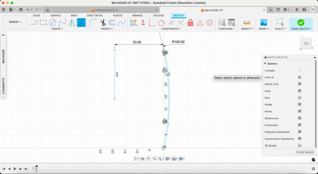
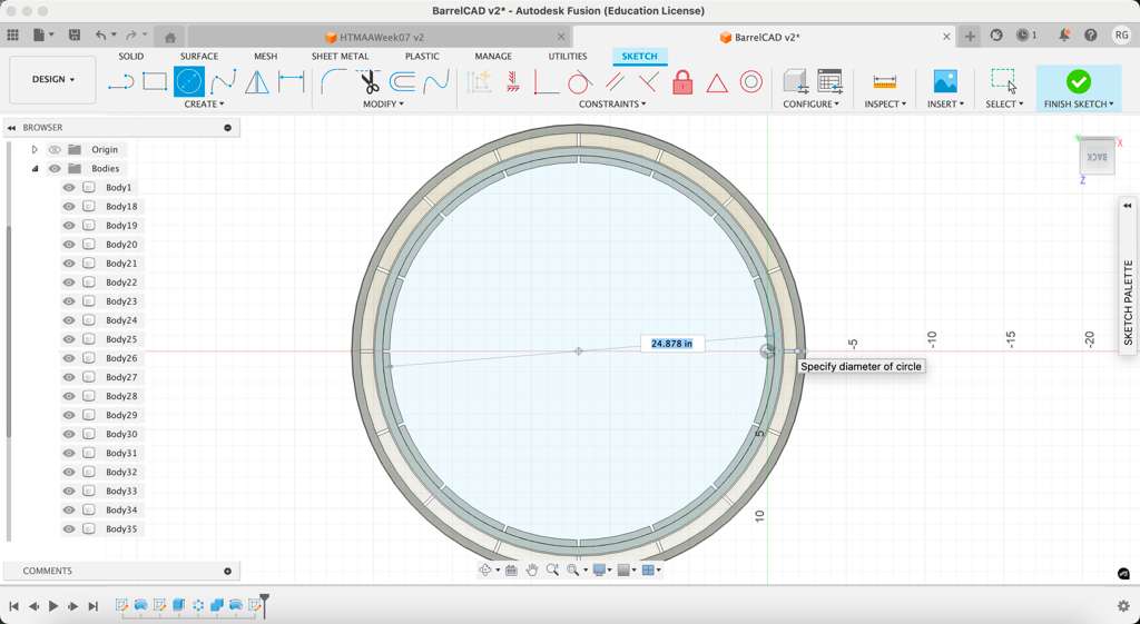
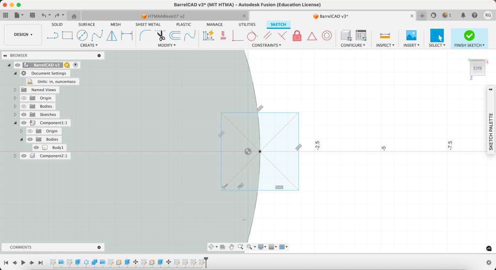
I got started on the CAD using Fusion360, which has a robust CAM software built in. I found helpful YouTube tutorials online which I followed, detailing the process of designing a 3D barrel. I began by tracing a 40in line on the XY plane and fixing both endpoints.
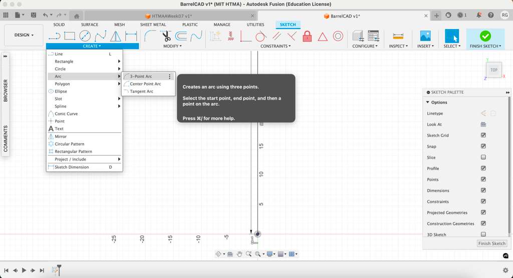
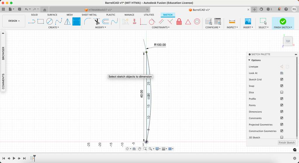
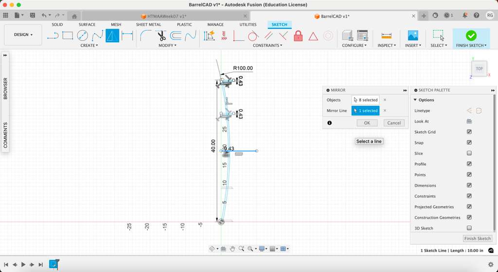
The next step is using the Create -> Arc -> 3-Point Arc toolpath to add the trademark bend of the barrel. I selected the two endpoints and the third point on the right. I set the radius to 2.5x the line length (100in) to match the rough flexibility of the wood I am using.
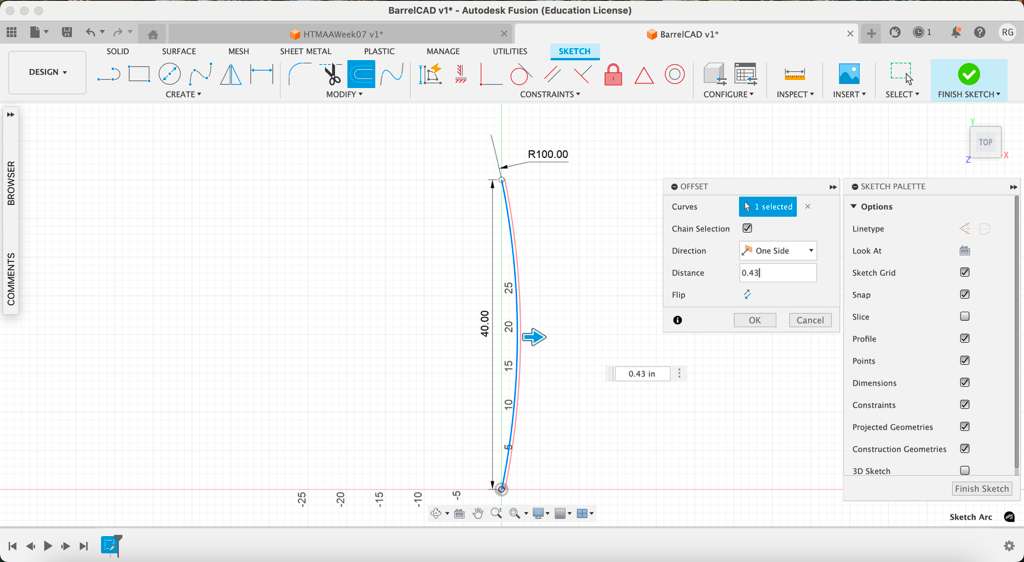
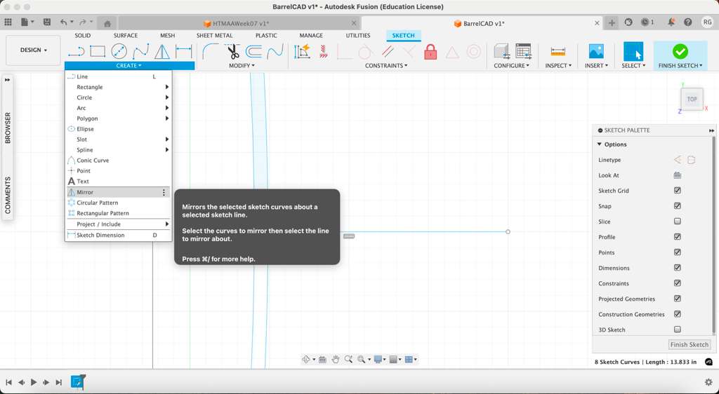
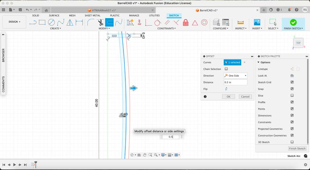
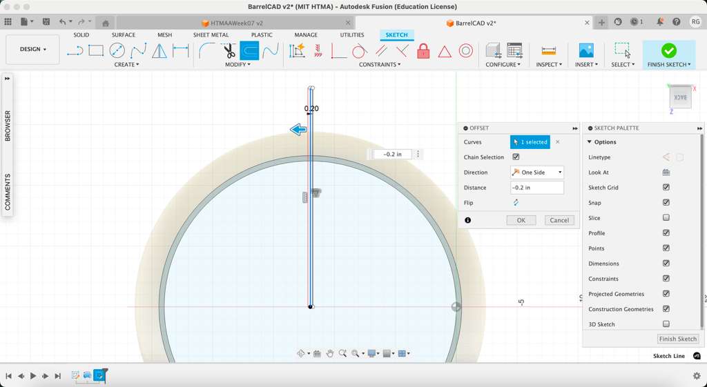
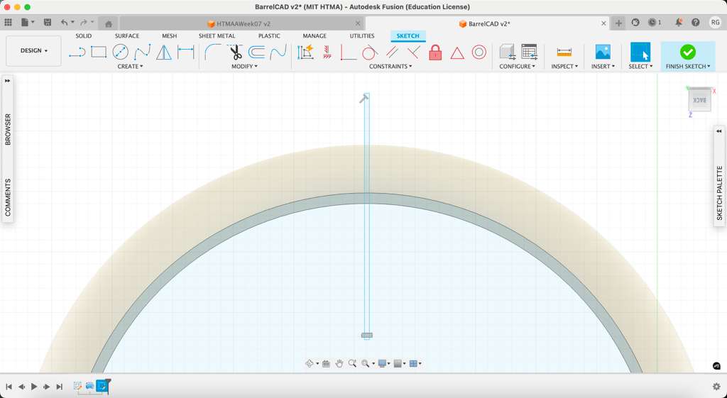
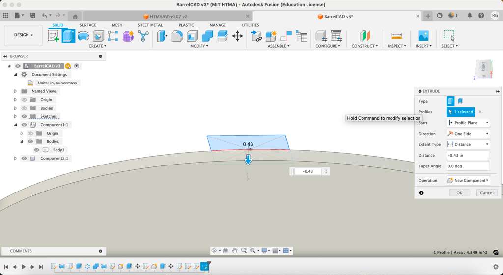
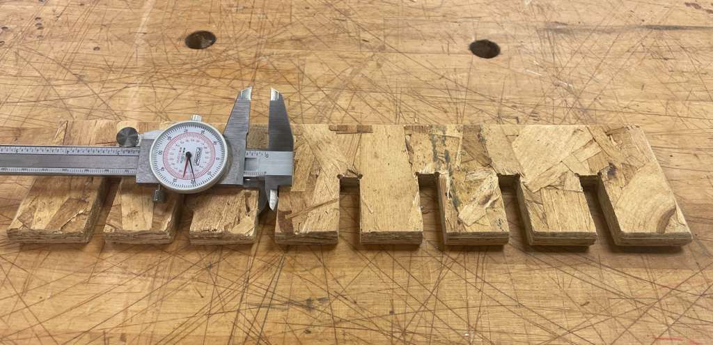
I used the Offset tool to add the thickness of the material I am using (0.43in) to the barrel. I also added wooden bands to hold the barrel shape together when assembled by drawing two lines out of the material with same thickess 0.43in (two bands on each half). Then I drew a line cutting across the midsection of the barrel to take advantage of the mirrow function for the bottom half.
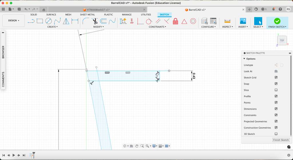
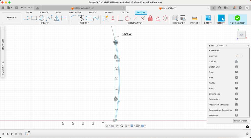
Once the lines were drawn and mirrored on the other half, I added another offset to account for the wooden bands. Then I deleted the helper lines, leaving the 2D projection of the bent wood and bands remaining.
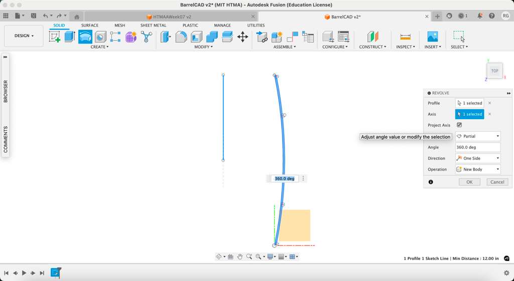
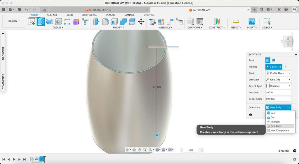
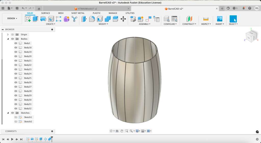
I drew a line to represent the middle axis of the barrel 20in away. Then I selected the Create -> Revolve toolpath and chose the barrel wood (without the bands) to create the 3D barrel shape.
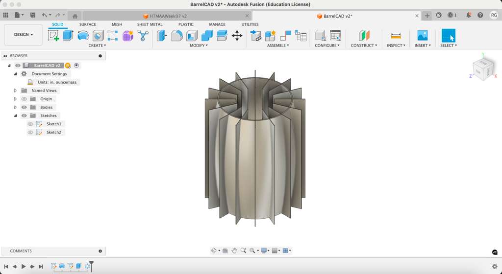
To create realistic slits between wood panels, I created a new sketch on top of the barrel edge. I drew a center line and used Offset to add a line on either side (before deleting the original one). I then closed the lines off at either ends to make a closed 2D rectangle shape.
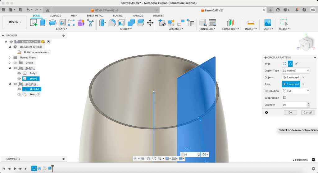
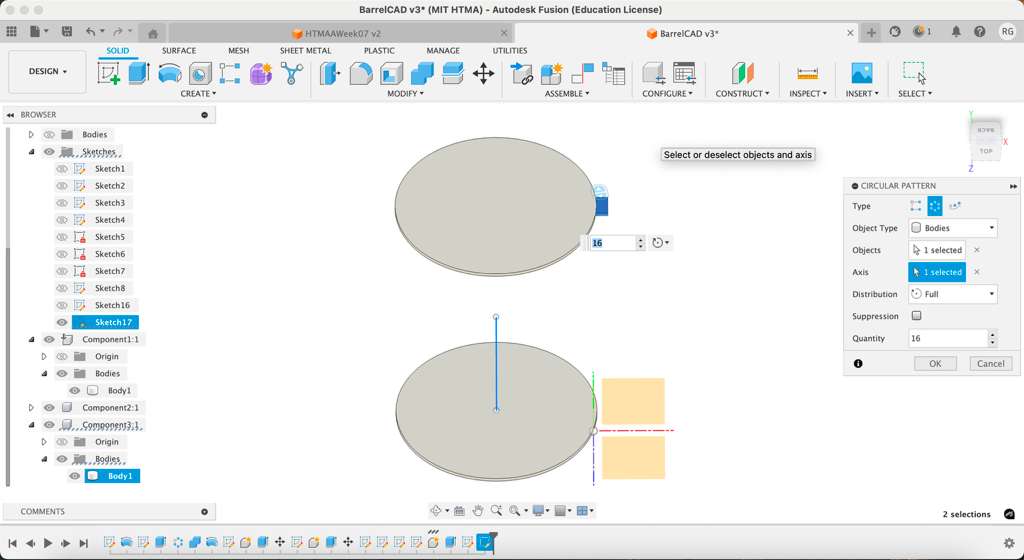
The rectangle was extruded to follow the entire length of the barrel as a 3D object. The next step was using the Create -> Pattern -> Circular Pattern toolpath to add multiple slits along the barrel circumference. I selected the slit as the object and the center line as the axis, adding 16 slits total.
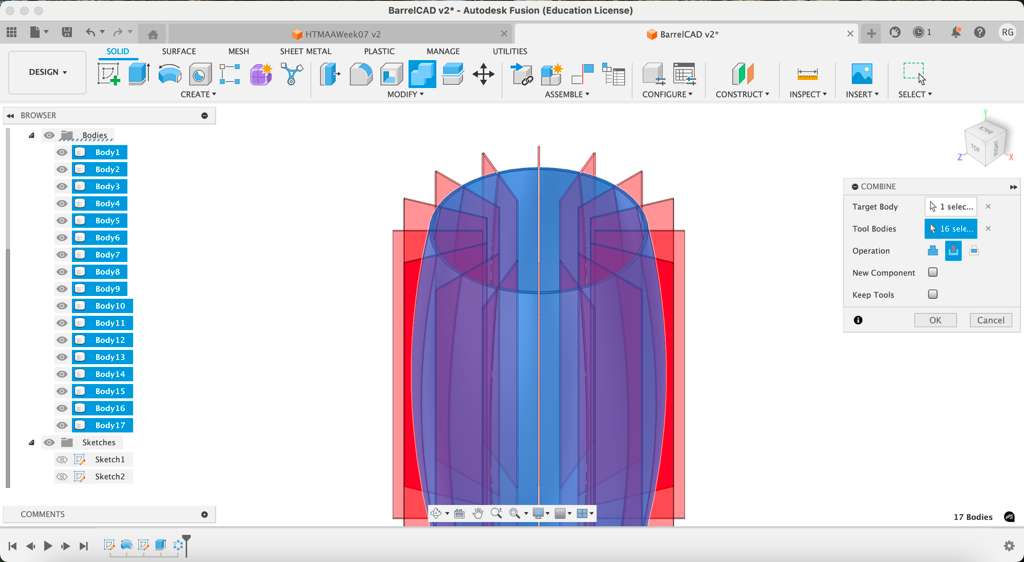
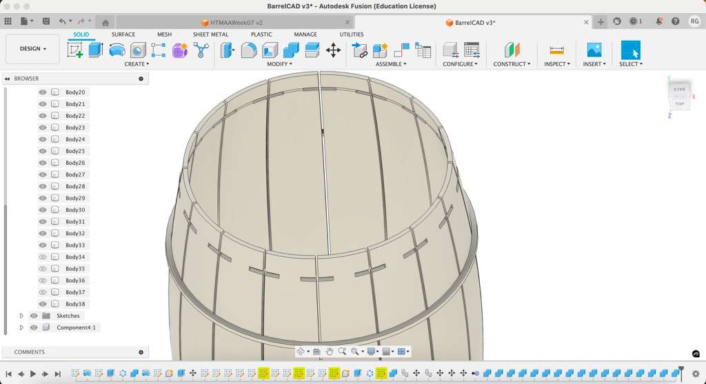
Now that the rectangles were in place, I followed the Modify -> Combine tool with these selections: Barrel = Target Body; Slits = Tool Bodies; Operation = Cut. This removed the rectangles and left visible slits in between the wood planks. Then I repeated the Circular Pattern process for the wooden bands to provide structure.
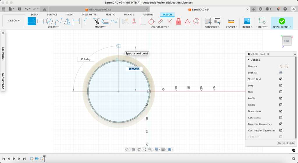
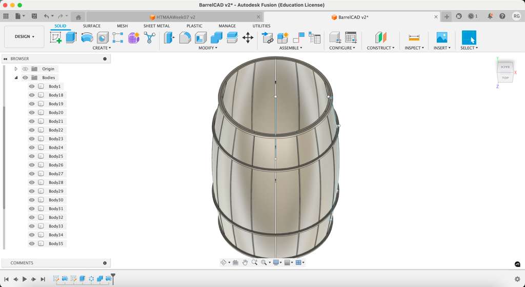
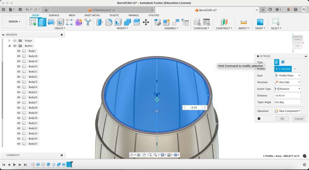
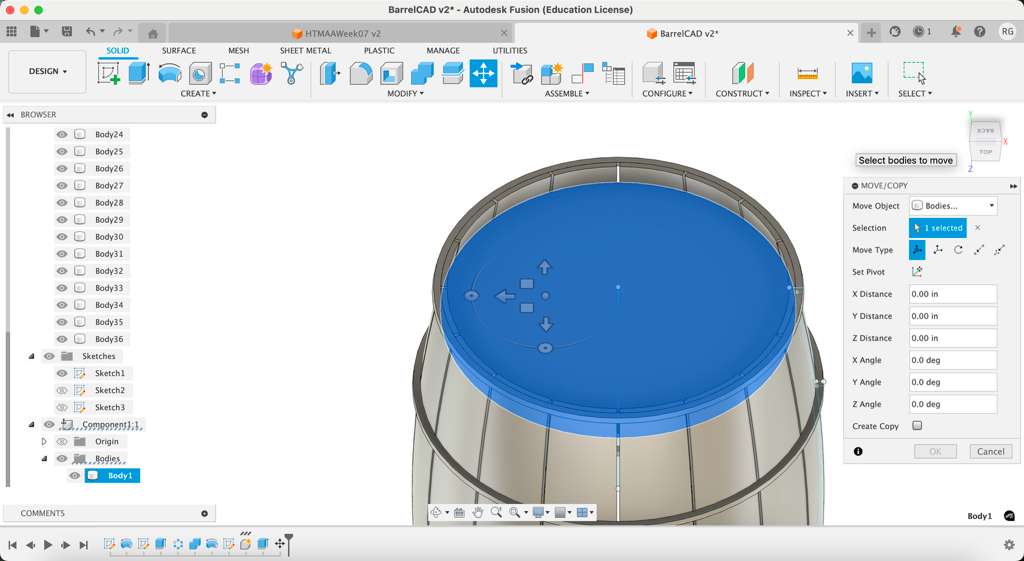
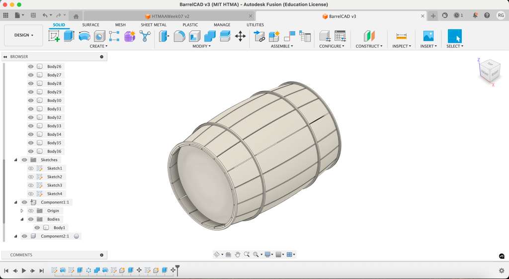
It was time to add caps at the end of the barrel. I created a sketch at either end and drew a circle on top, which I extruded by the thickness of the material. The disk was then moved down into the barrel by 3in to help keep the material together.
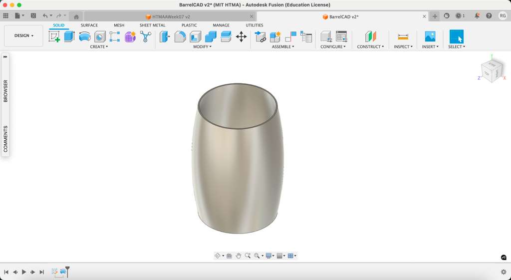
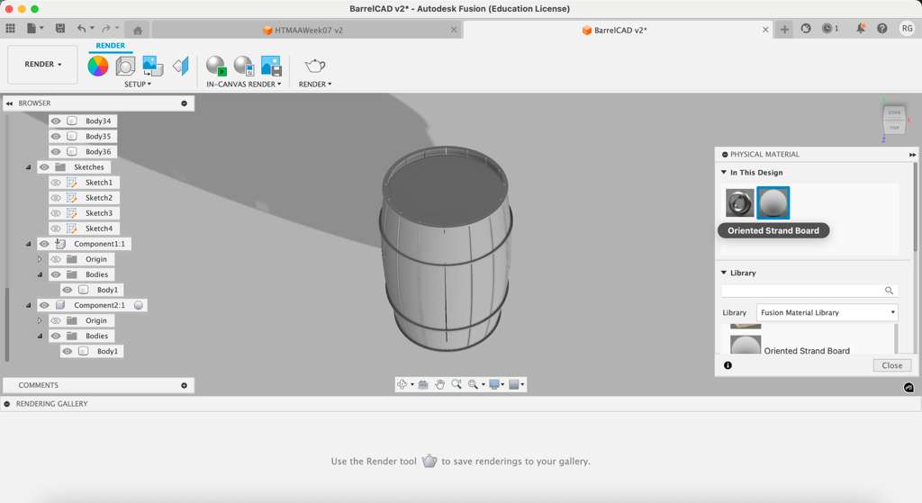
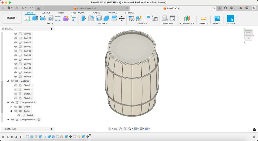
The last step was adding some color! This week we are using OSB, which I found in the Render page under the Wood selections. This is what my final 3D CAD for the barrel looks like:
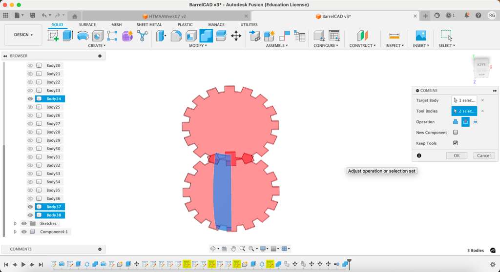
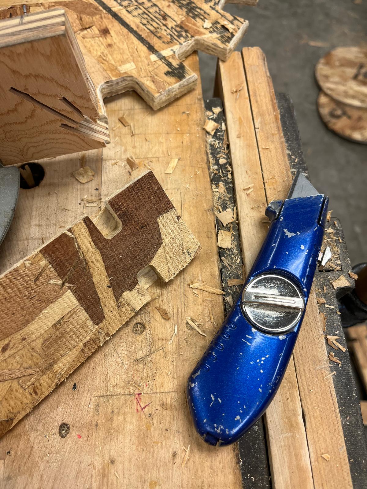
Before we get to machining, I have a couple design features to add. The first is joints between the caps at the end and the staves along the side. This will help keep the design in place and keep integrity of the structure (hopefully). I added what resembled gear teeth to the caps by sketching a rectangle at one end, extruding it by 0.43in, and using the Create Circular Pattern worklow to make 16 of them.
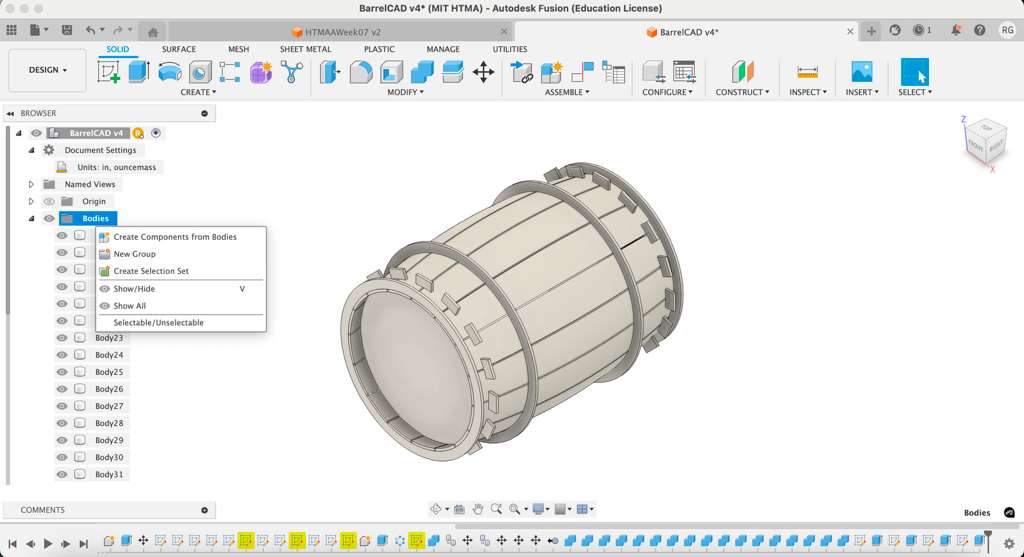
I copied the gear teeth design and replicated it on the bottom cap. The product still had overlap between the staves and the caps which I had to remove after. I used the Combine tool to cut gear-sized slits in the staves that the cap would fit into. The final step was making all Bodies into Components for the Arrange tool used later.
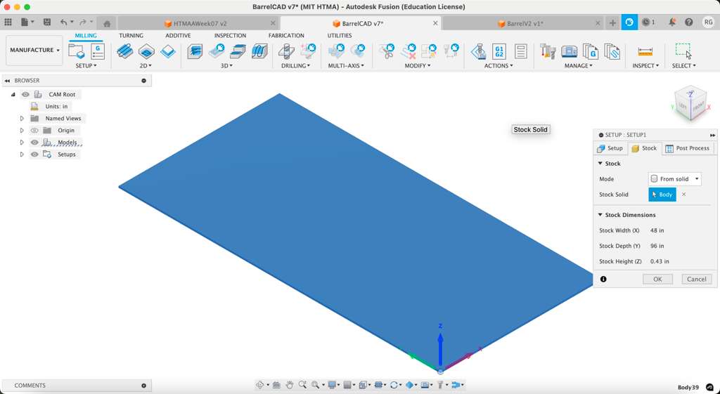
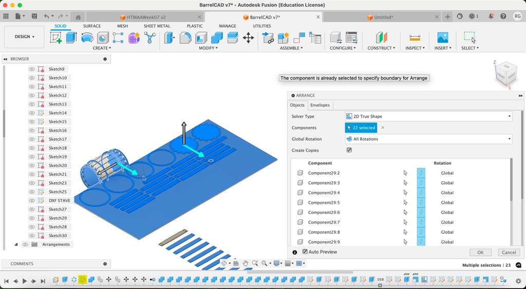
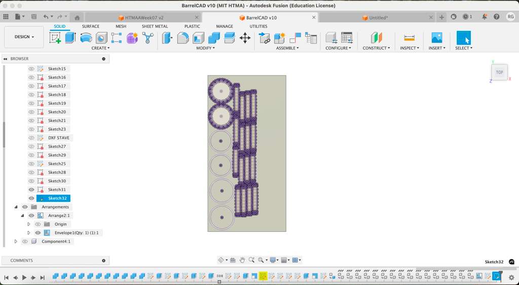
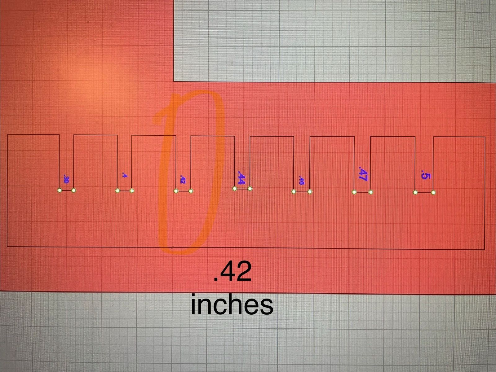
The next step was designing my stock, which was a 96in x 48in OSB board with 0.43in thickness. Using the Arrange function, I was able to easily project the flat parts (objects) onto the stock (envelope) with 1in clearance, but struggled with the bent staves. After spending some time wathcing tutorials and attending office hours, I was able to receive a bent stave as a 2D projection through UV unfolding in Blender and flattening along the axis (shoutout Gert!). The Arrange feature then added everything in line on top of the stock, and I used the Project tool to etch the surface with my part sketches. On a second layer on top, I added infinitesimal dots on top of inside corners which will need smoothing due to the circular shape of the end mill. The two sketch layers were exported as DXF files and sent to TAs for approval before cutting.
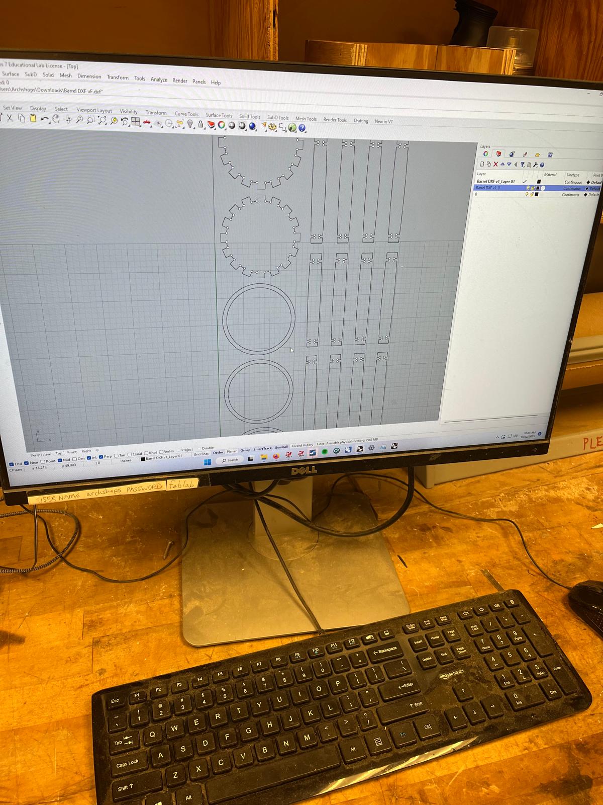
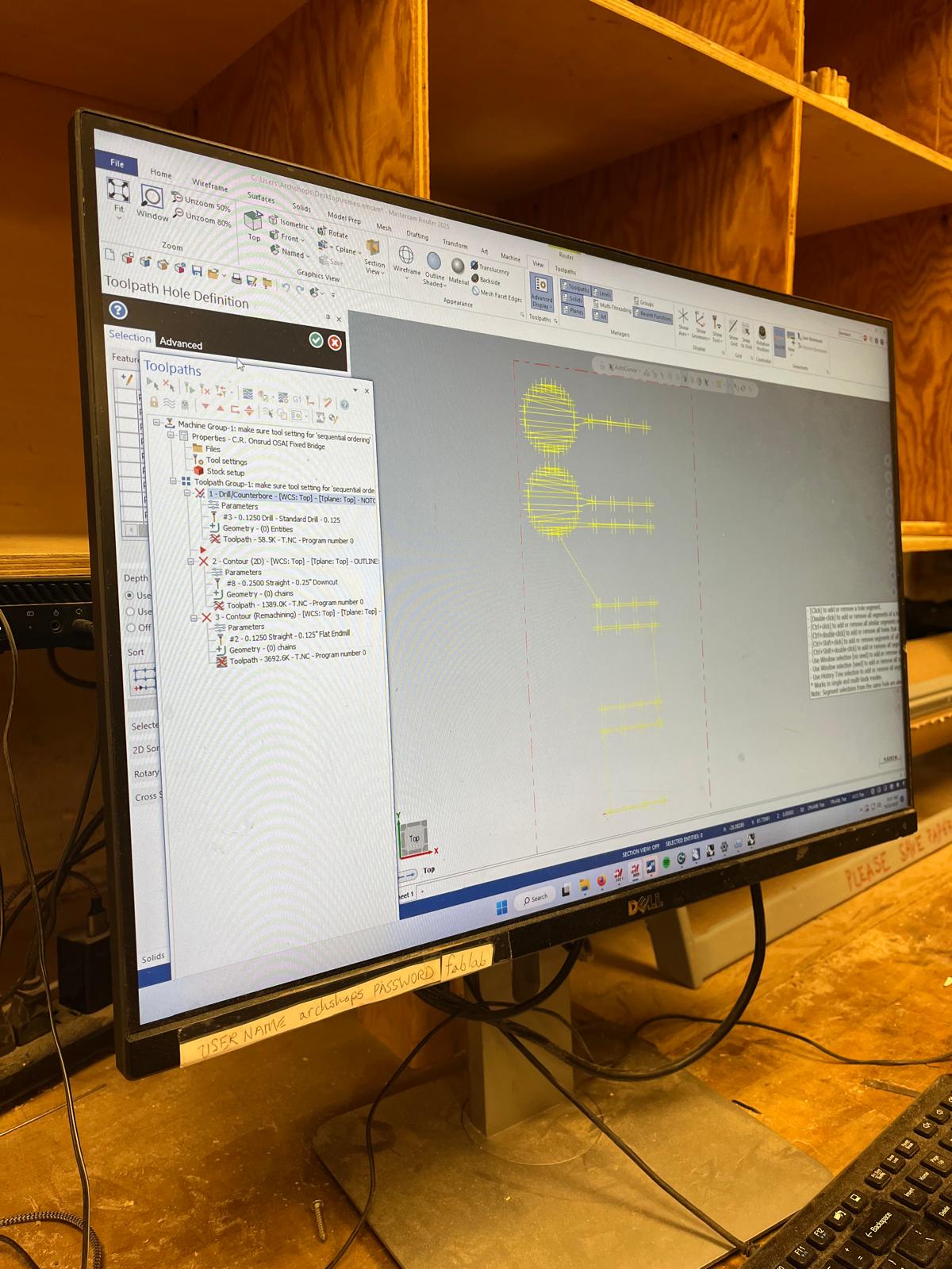
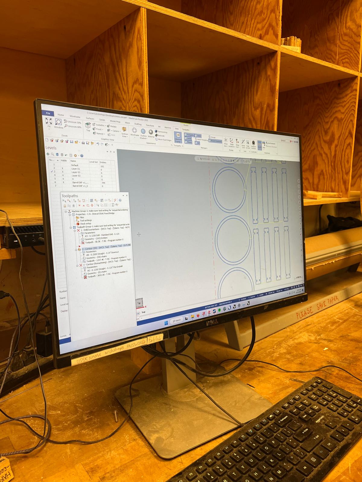
The final step in the design process was taking the DXF file and uploading it to Mastercam for toolpath planning. Chris helped me walk through the setup and ensured that my points for inside corners were on a separate layer.
Milling Assembly
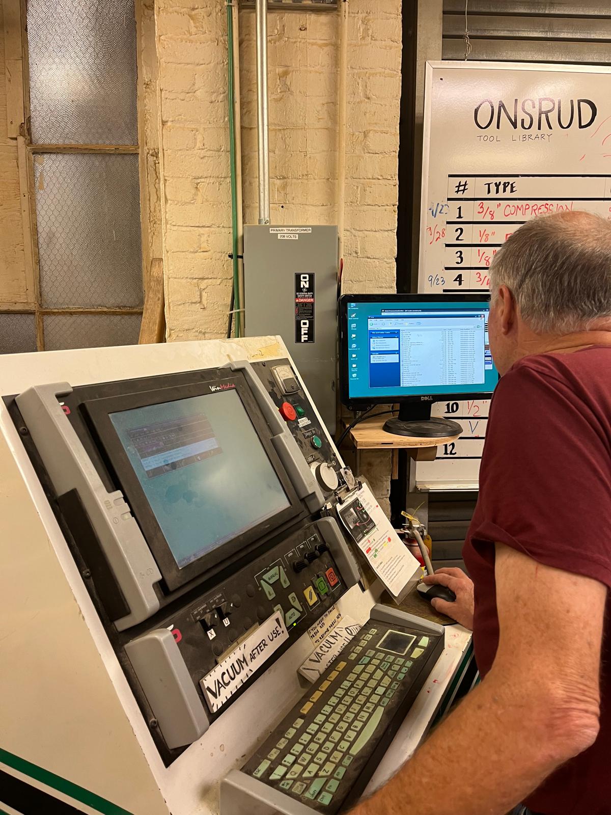
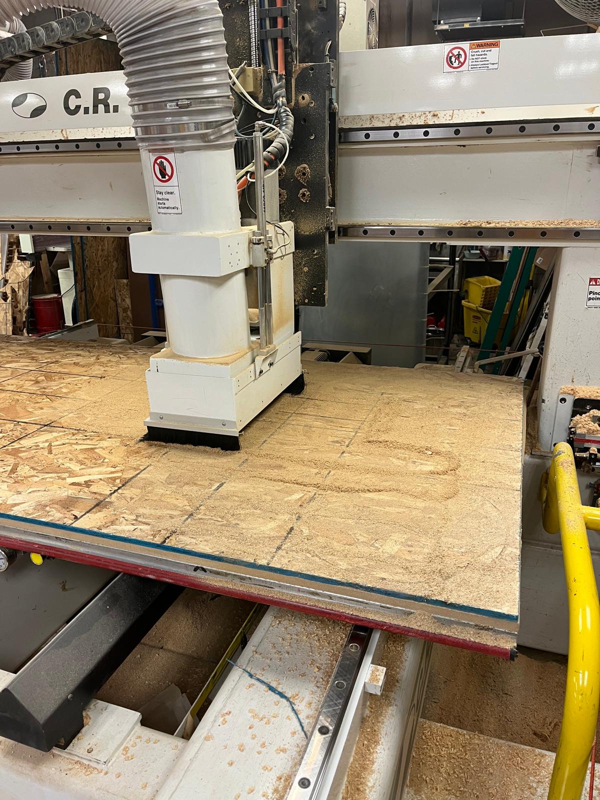
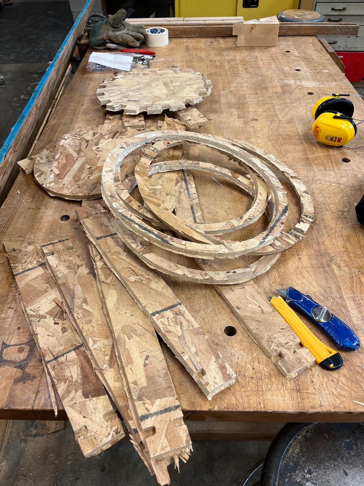
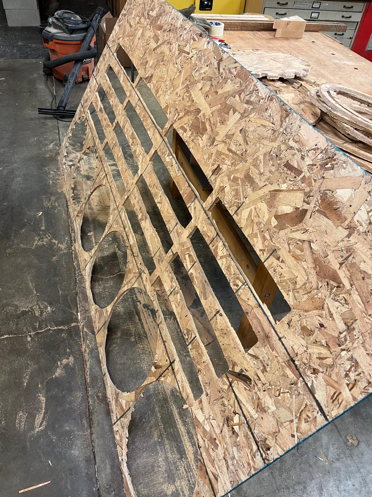
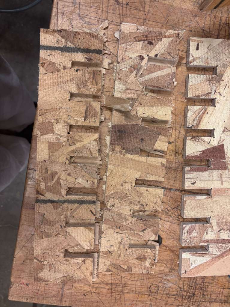
We loaded the CAM file onto a USB drive and uploaded it to the Onsrud machine, which began the milling process. Once the milling was done (approx. 30min) I took the OSB out and used the box cutter to cut the parts free from the board.
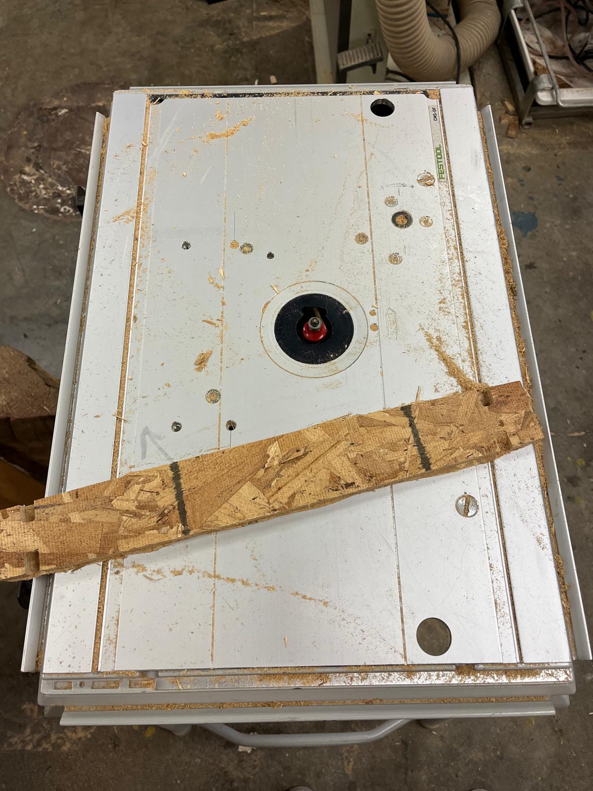
This milling process left a characteristic "onion skin" which I removed using the circular saw. I passed the parts through counter-clockwise against the rotation of the machine to smoothen the edges. The hard to reach parts, like the insides of the staves, I removed manually with the box cutter.
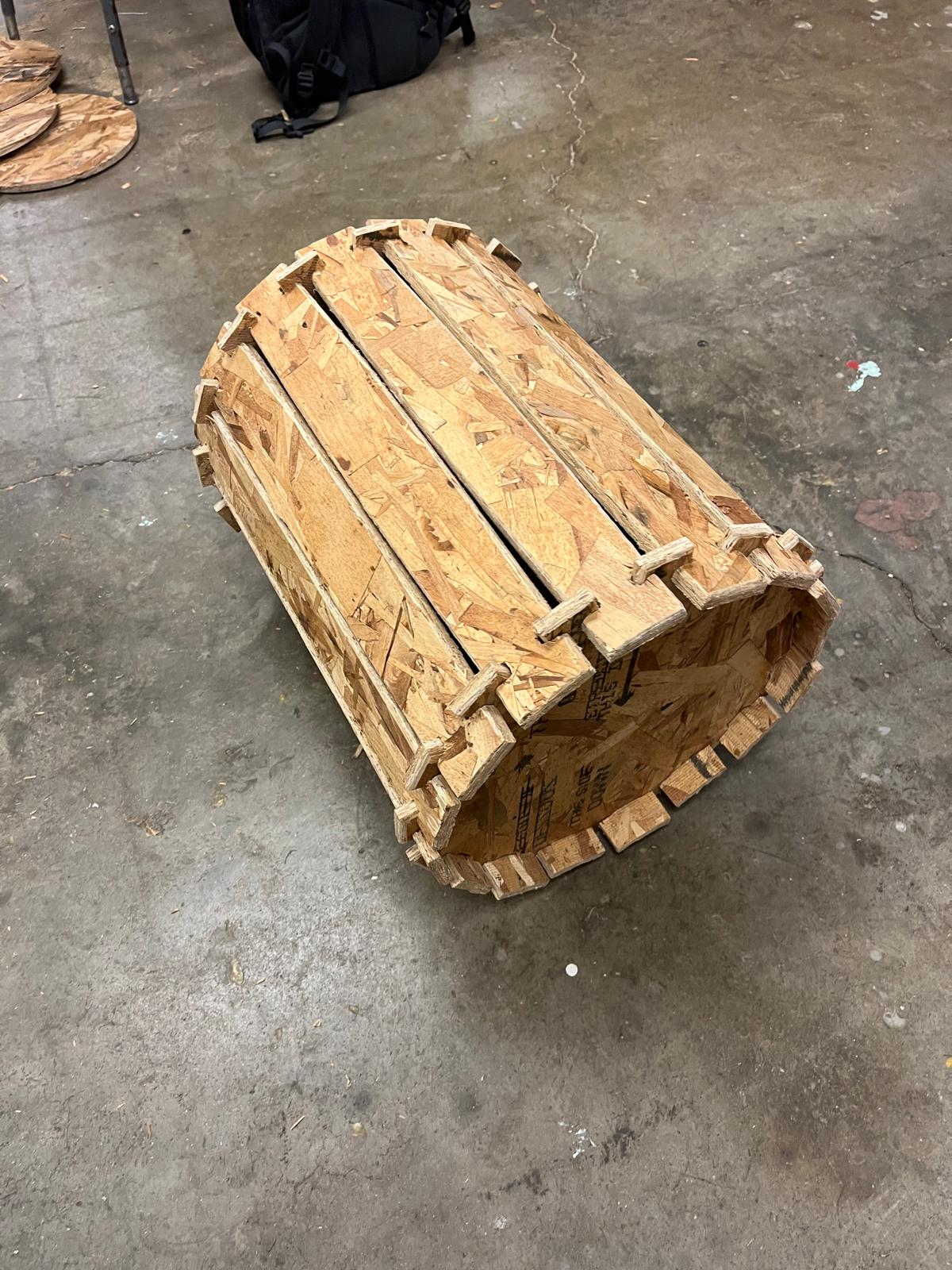
The last step was assembly! I placed my pieces together and achieved the barrel structure. However, as expected, the rigidness of OSB and lack of flexibility without splintering made it impossible to constrain the staves to bend as originally planned. Therefore, the wine barrel looks more like the Clash Royale Goblin barrel, but I am still quite happy with the end result!
Chris ran our safety training and walked us through standard operations of all machines. We tested runout, alignment, fixturing, speeds, feeds, materials, and toolpaths for the Onsrud machine.