Individual Assignment
My goals for this week were three-fold:
- Get ahead on my final project and make one of the subsystems.
- Continue practicing the Design -> Mill -> Assemble workflow with multiple boards.
- Use the computer vision module demonstrated in recitation.
Board #1
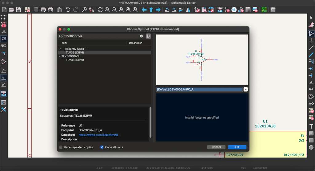
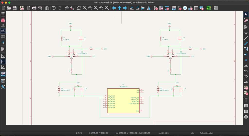
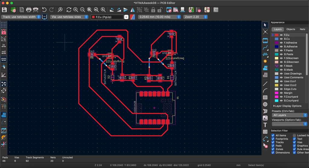
The first design drew inspiration from perimeter guide wires that help robots navigate outdoor terrain, using basic E&M physics I learned in 8.02. The idea was simple: generating an AC signal down a wire, which (using the right-hand-rule) creates a magnetic field perpendicular to the electric field. This magnetic field can then be sensed using a simple LC bandpass-esque filter. The circuit picks up the B-field and propagates a corresponding E-field, with a resonance frequency equal to the inverse of 2π × sqrt(LC). The resonance helps to keep out noise from nearby circuits and isolate the frequency from the AC wire. It is important to choose the right L & C values to create resonance at roughly 30kHz which is above hearing range. Once the signal is cleaned it is still quite weak, so an amplifier circuit is required to boost it. I used the non-inverting pin of an Op-Amp as the input with a gain of 100 to create a strong output. The last step was adding a rectifier circuit using diodes to convert the Op-Amp AC signal into DC voltage for the microcontroller. The XIAO RP2040 I used does have Analog pins so this step was not required but still good practice to learn. Once established, the circuit was replicated on the other side. This way the MCU receives one signal from the left and one signal from the right to understand its position. Then a simple controls algorithm can be programmed to move the robot's position based on the difference of the two readings. Strong left signal and weak right signal means turn left, and vice-versa. The schematic and PCB layout were both designed in KiCad, and I am hoping to use this circuit to learn how to mill boards with vias and traces on the bottom layer.
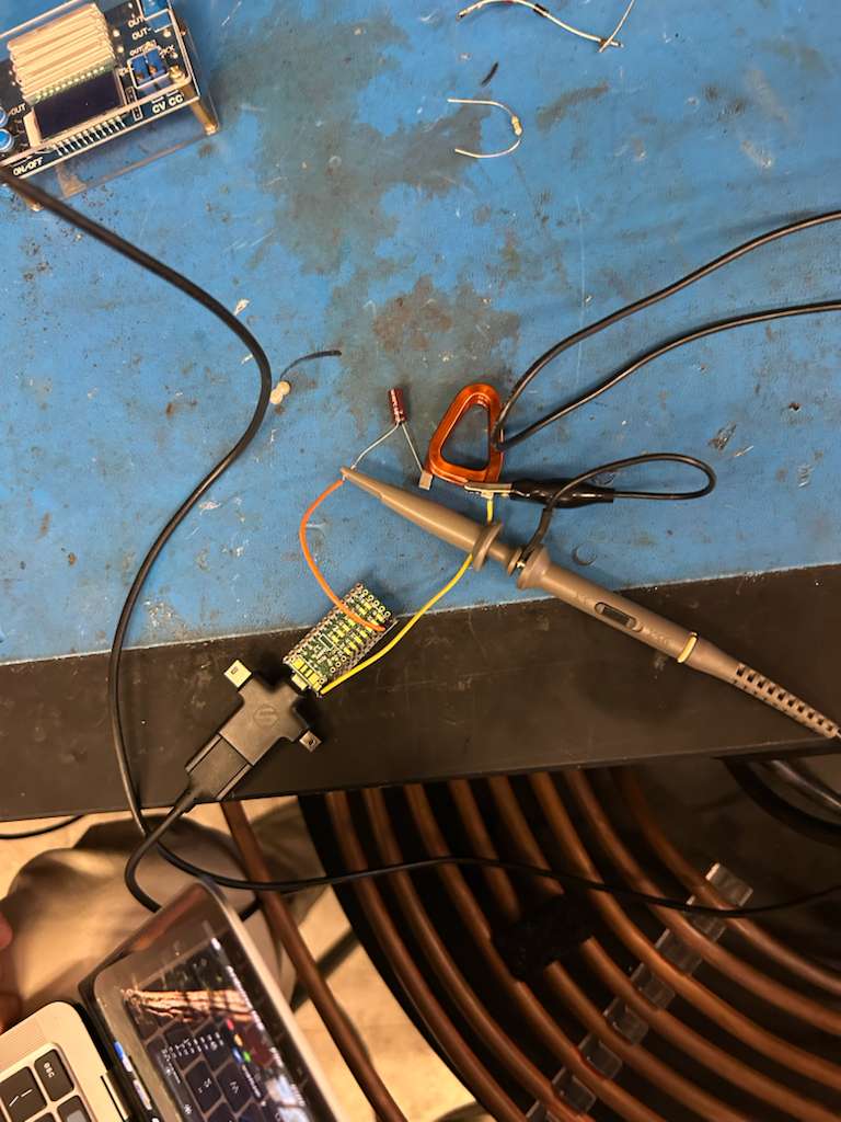
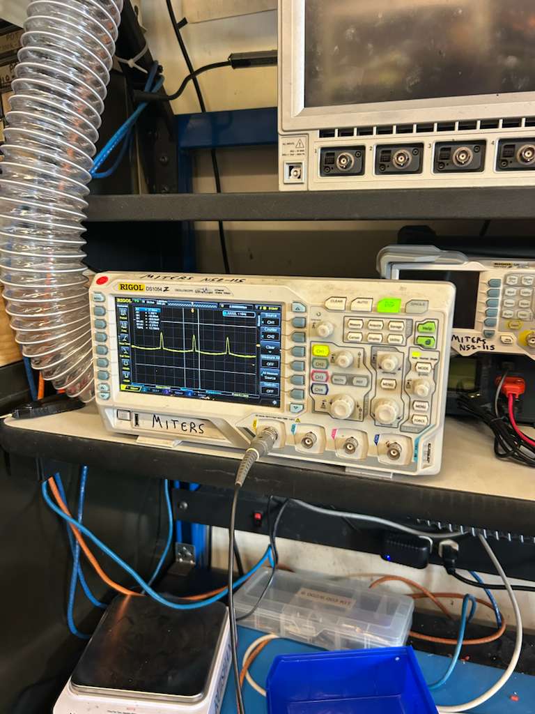
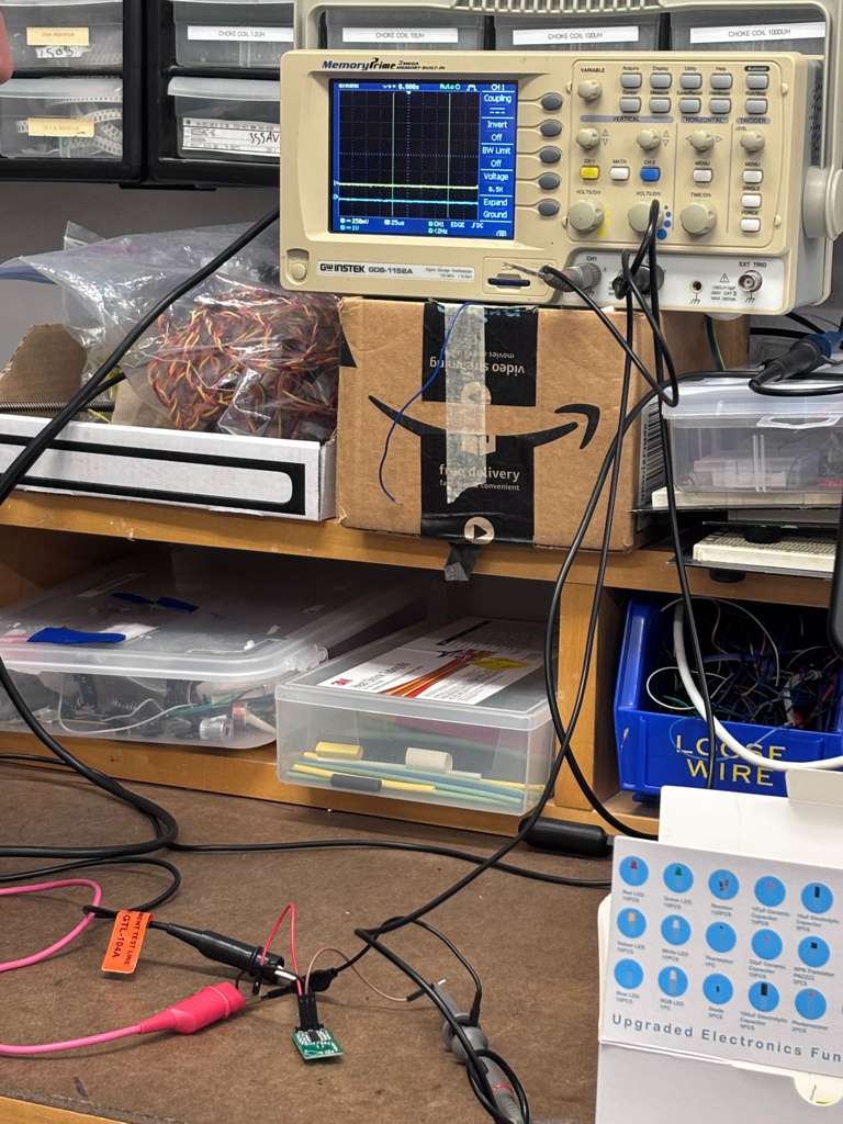
The class inventory unfortunately did not have any axial inductors / solenoids I could use for my circuit, so following Prof. Gershenfeld's advice, I decided to sense magnetic field through a different component: the Hall Effect sensor in Board #2. But before that, I found a solenoid in the MITErs makerspace and soldered a quick circuit for it, using a LC circuit setup described above. We were able to detect the magnetic field caused by a 30kHz signal (LC circuit resonance) outputted by a function generator and even noticed the orientation difference (N-S direction). This was measured through both an oscilloscope, and later by connecting a Teensy microcontroller to the circuit and reading the values from my computer.
Board #2
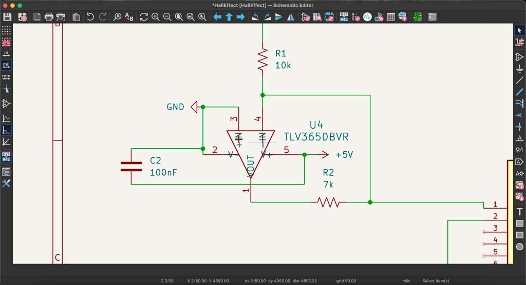
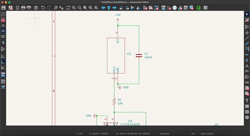
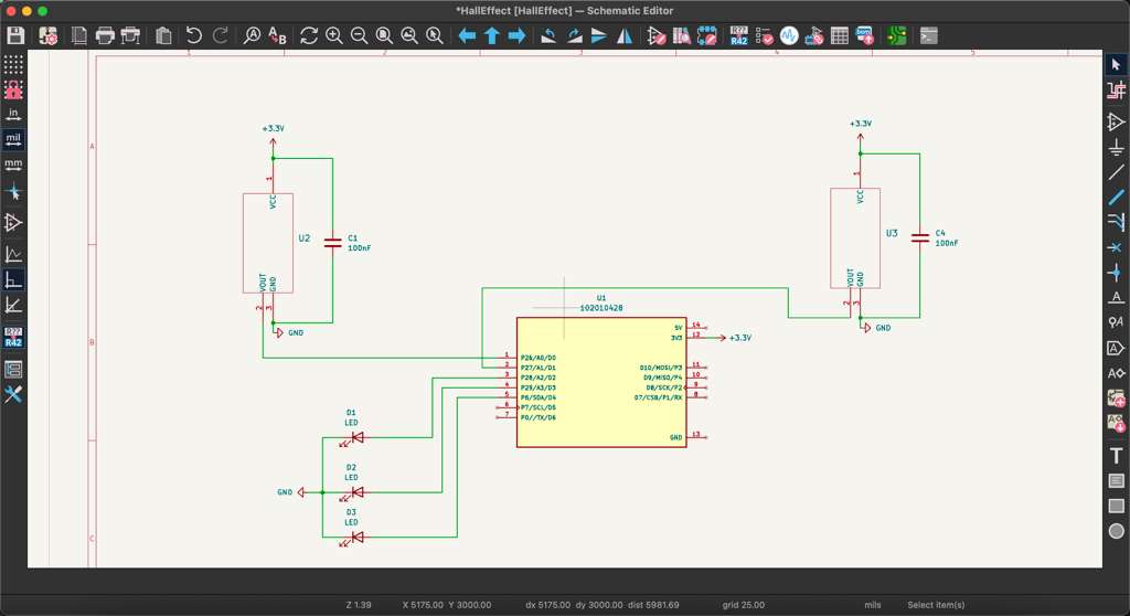
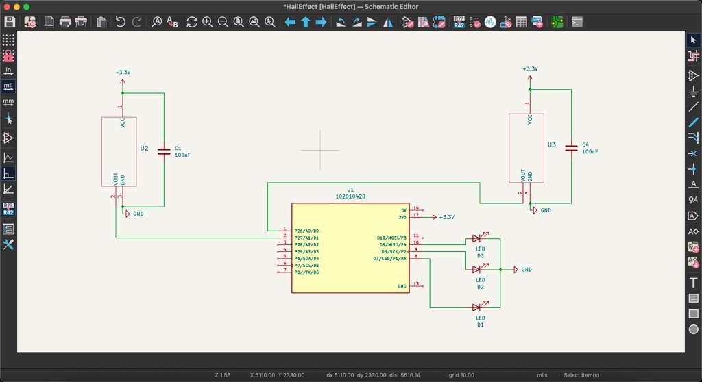
The second design borrowed the same guide wire concept but used Hall Effect sensors for the magnetic field. I used the analog linear 1-axis Hall Effect sensors that generated analog signal for the magnetic field perpendicular to the component's face. After reading through the datasheet, I placed two Hall effect sensors on either side of the board. I also added three LEDs that could be programmed to display position based on their relative lighting up. If the MCU was too far on the right, the LEDs on the left would be off and the one on the right would be red. The goal of the controls algorithm would have been displayed to maintain consistent readings from the middle LED. From my initial understanding, the active components had to be powered by the MCU's 5V pin. This created an issue where the Analog pins on the XIAO only read up to 3.3V. Therefore, I designed an amplifier circuit using the inverting pin of the Op-Amp. With a gain of 0.7, the Op-Amp circuit limited the maximum current to below 3.3V shielding the MCU.
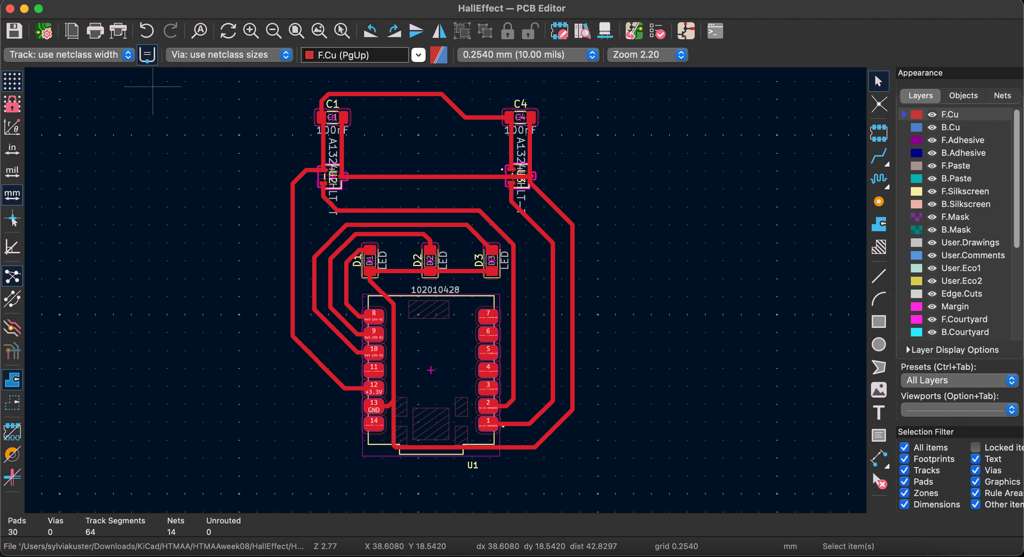
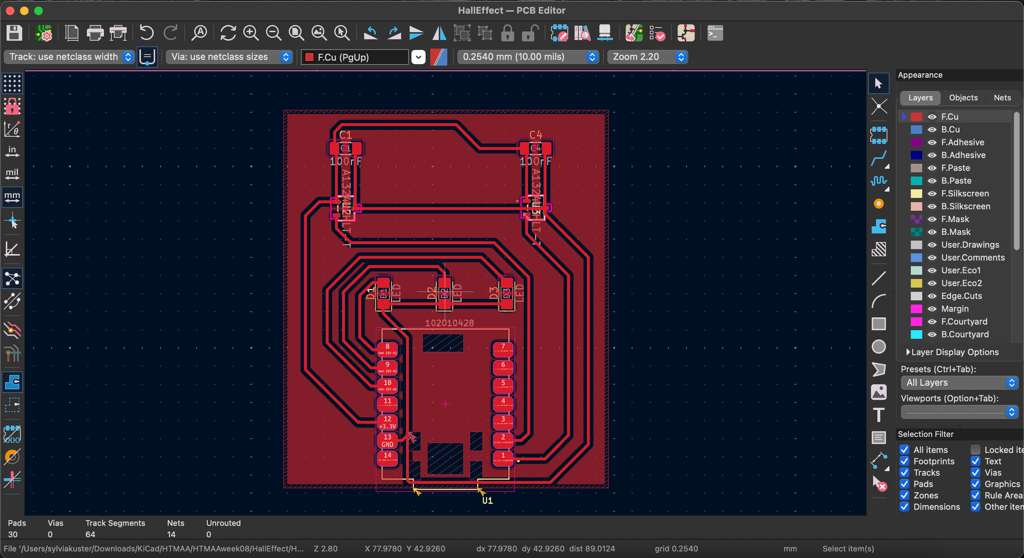
After office hours with Anthony, I realized the Hall Effect sensor also worked with 3.3V Vcc power from the XIAO, which automatically limited the maximum voltage that could be generated to 3.3V. Therefore, I redesigned the entire circuit and it became much much simpler. The amplifier circuit was removed, leaving only the Hall Effect sensors directly connected to the analog pins on the XIAO and supplemented only by a 100nF decoupling capacitors for steady power supply. I laid out all the traces on the PCB editor and finalized the board without use of the bottom layer.
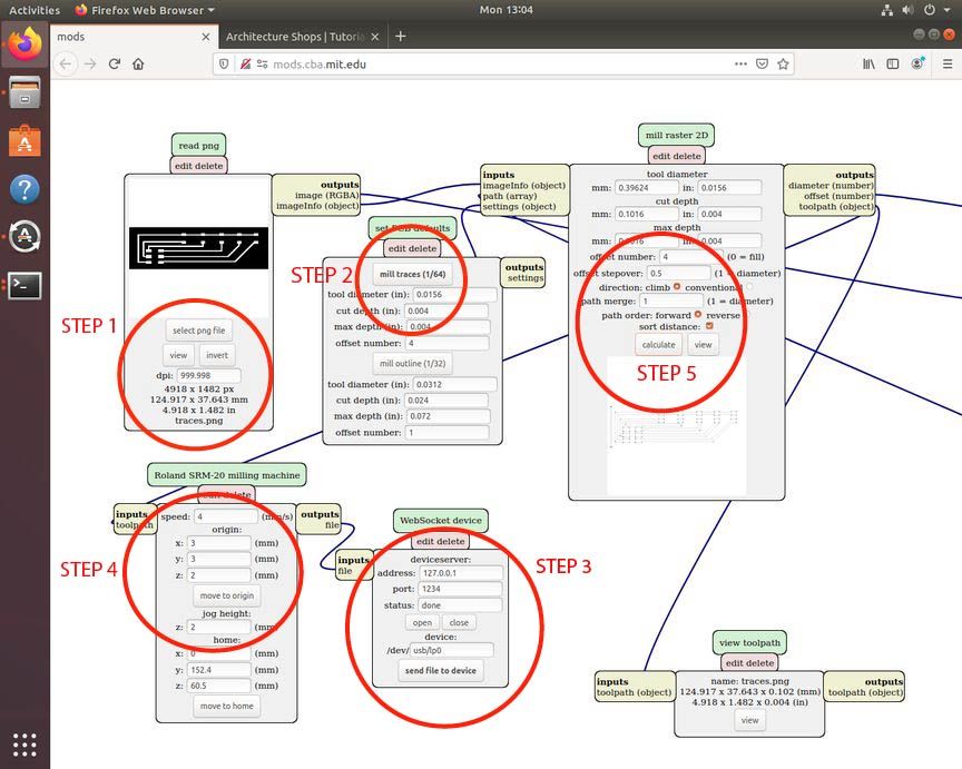
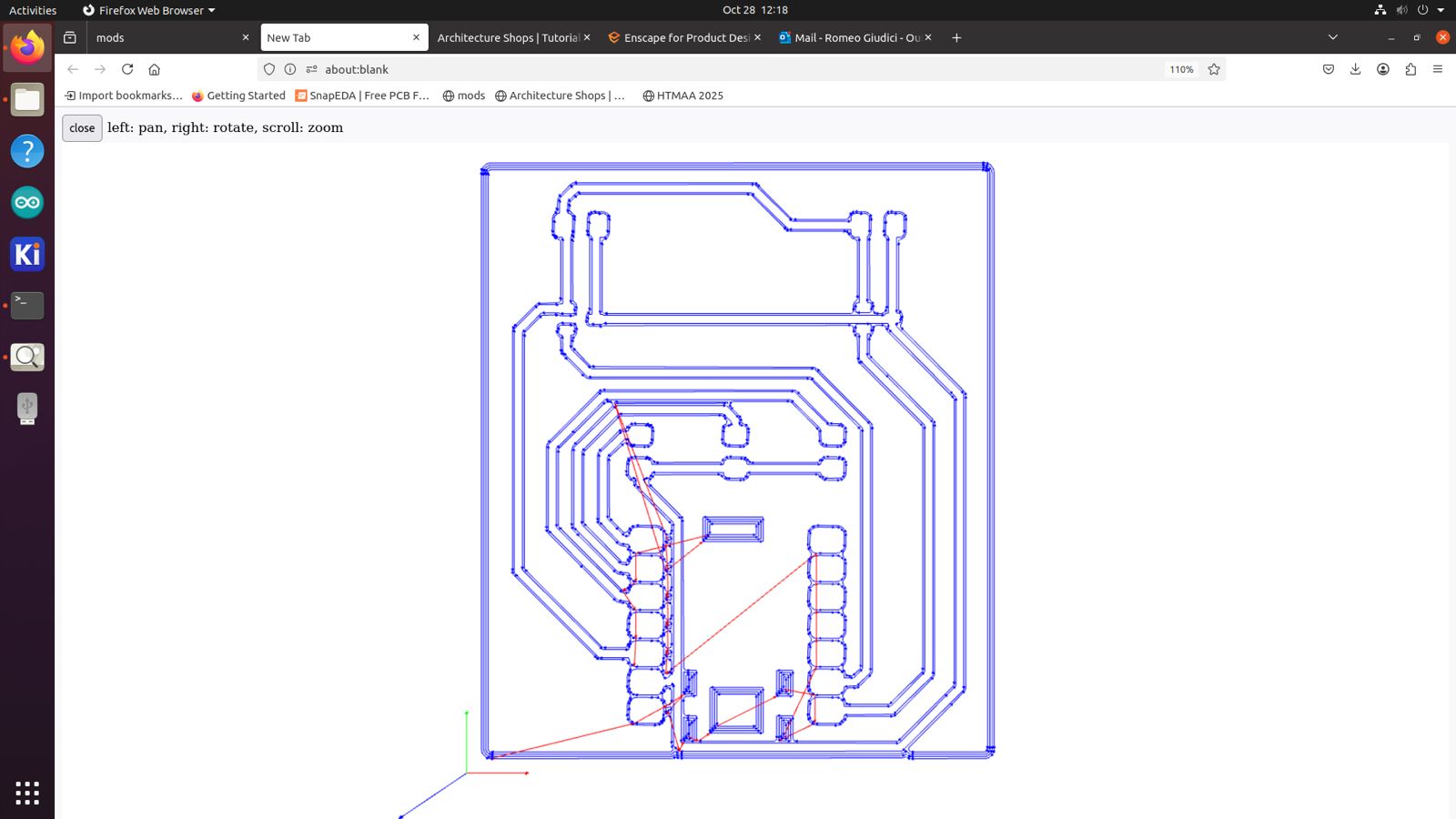
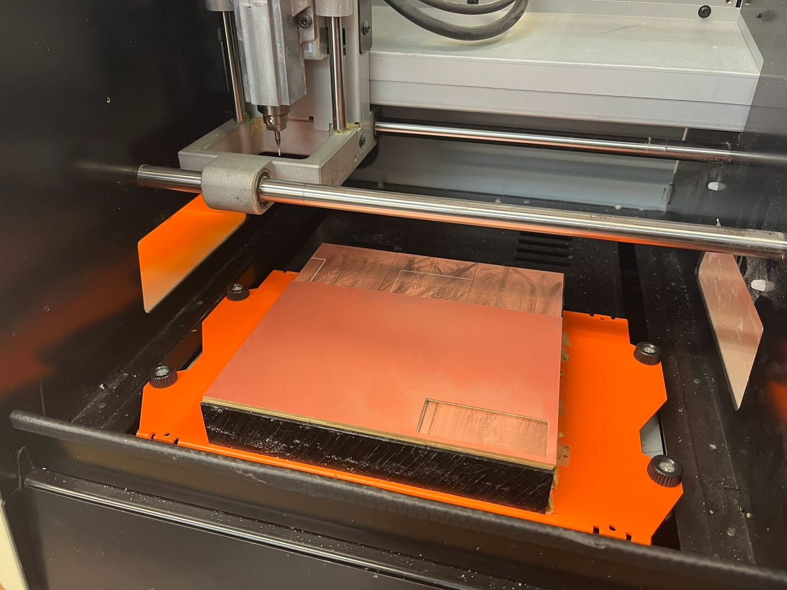
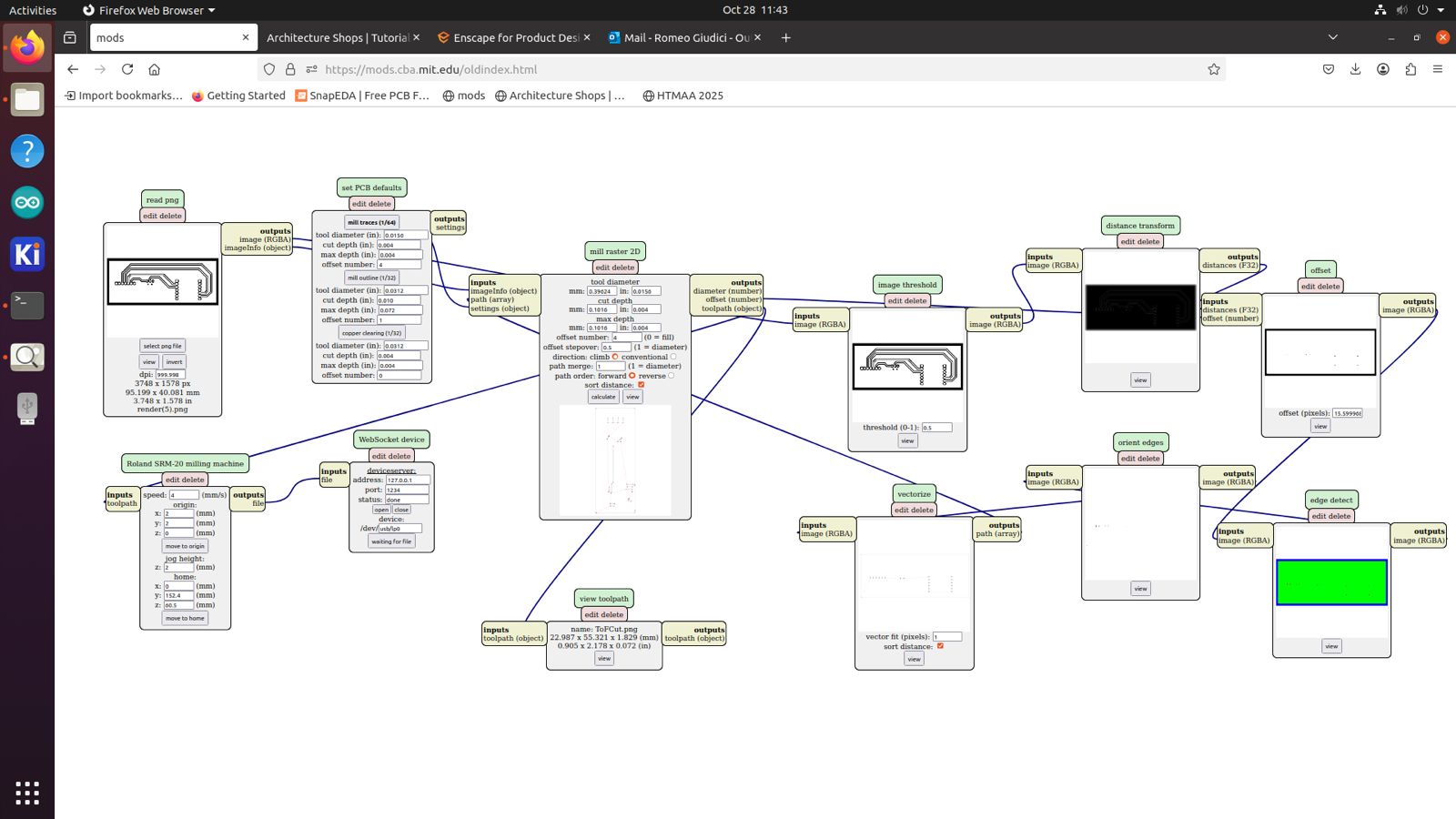
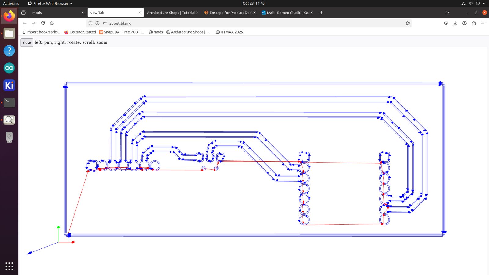
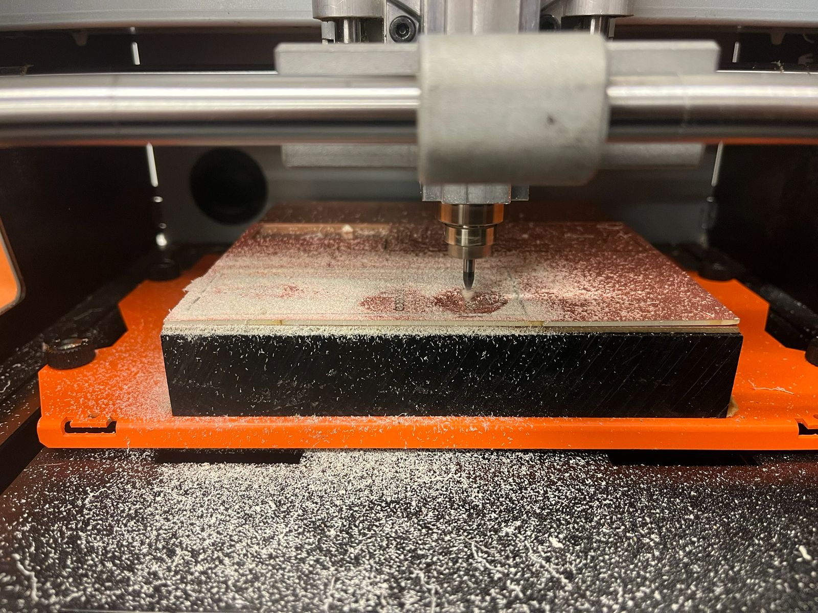
Once the KiCad design was finished, I exported it as a Gerber file and used Quentin's gerber2img converter to create a .png file of the top F.Cu layer and Edge.Cuts board outline. In the Architecture shop, I used the desktop connected to the Modela PCB mill to operate the Mods cutting software, which calculates the toolpath for the board to be cut. I used the 1/64" endmill for the traces and set the XY origin on the computer, before finalizing the Z coordinate by unscrewing the endmill and zeroing it on the board. Once the traces were complete, I repeated the process with the 1/32" endmill for the board outline.
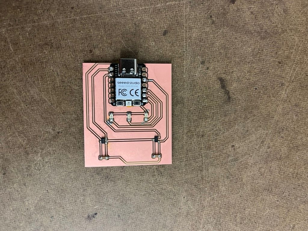
Once the milling was done, I went over to the assembly area and began soldering the components. I found the capacitors, diodes, and Hall Effect sensors in the cabinets on top of the soldering desk. I began the process of adding flux on the pad, tinning the soldering iron tip, placing the component on top of the pad, and adding solder to connect the joint. LED orientation matters, so always make sure you line up the green line (cathode) with GND. I soldered the XIAO package to the board and finished the assembly. The next step was the programming to sense magnetic field, which I did with a toy fridge magnet I found in my house.
Board #3
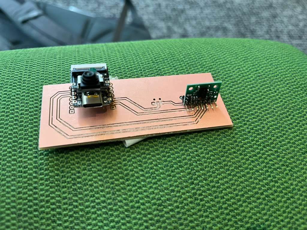
The final board design was catered much more to my final project and learning how to use computer vision. I had an office hours session with Anthony, who kindly brought me back down to earth with my mosquito laser idea. The components in the inventory and timeline of the class would have made the achieving the resolution required close to impossible without lots of money. I decided to pivot my idea slightly from mosquitos and drew inspiration from three things:
- 1. Recitation for the week. The session walked through edge AI use cases and how to implement them; I wanted to use this technology for some motion tracking module.
- 2. Machine week EECS shop 2023. The group assignment was a hilarious concept using the ESP32 and Nerf darts to identify and shoot offenders of Prof. Gershenfeld's "Don't Dribble In" policy. The use of motion tracking as input creating a target output seemed really fun.
- 3. Clay shooting. Last year for Thanksgiving, I brought my very European family to a ranch outside Dallas, Texas. Among other culture shocks, my family really enjoyed the clay shooting range, which had orange disks flying from different stations. The goal was to find these disks, aim, and shoot them down.
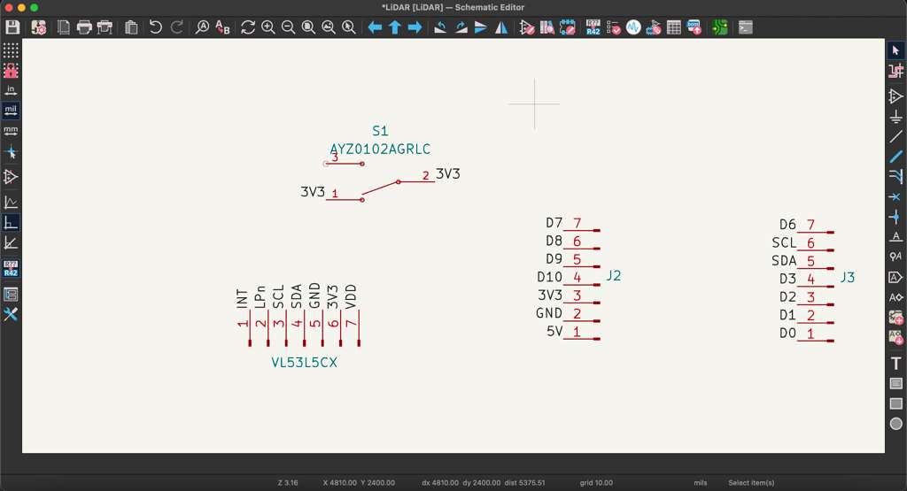
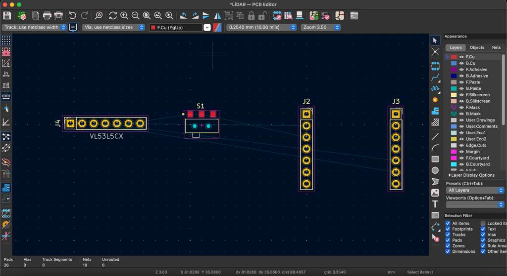
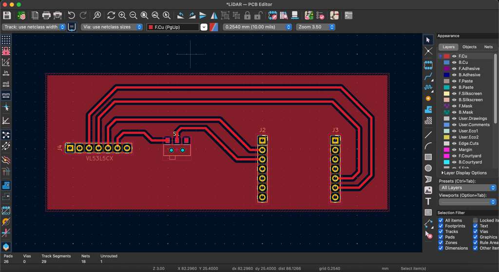
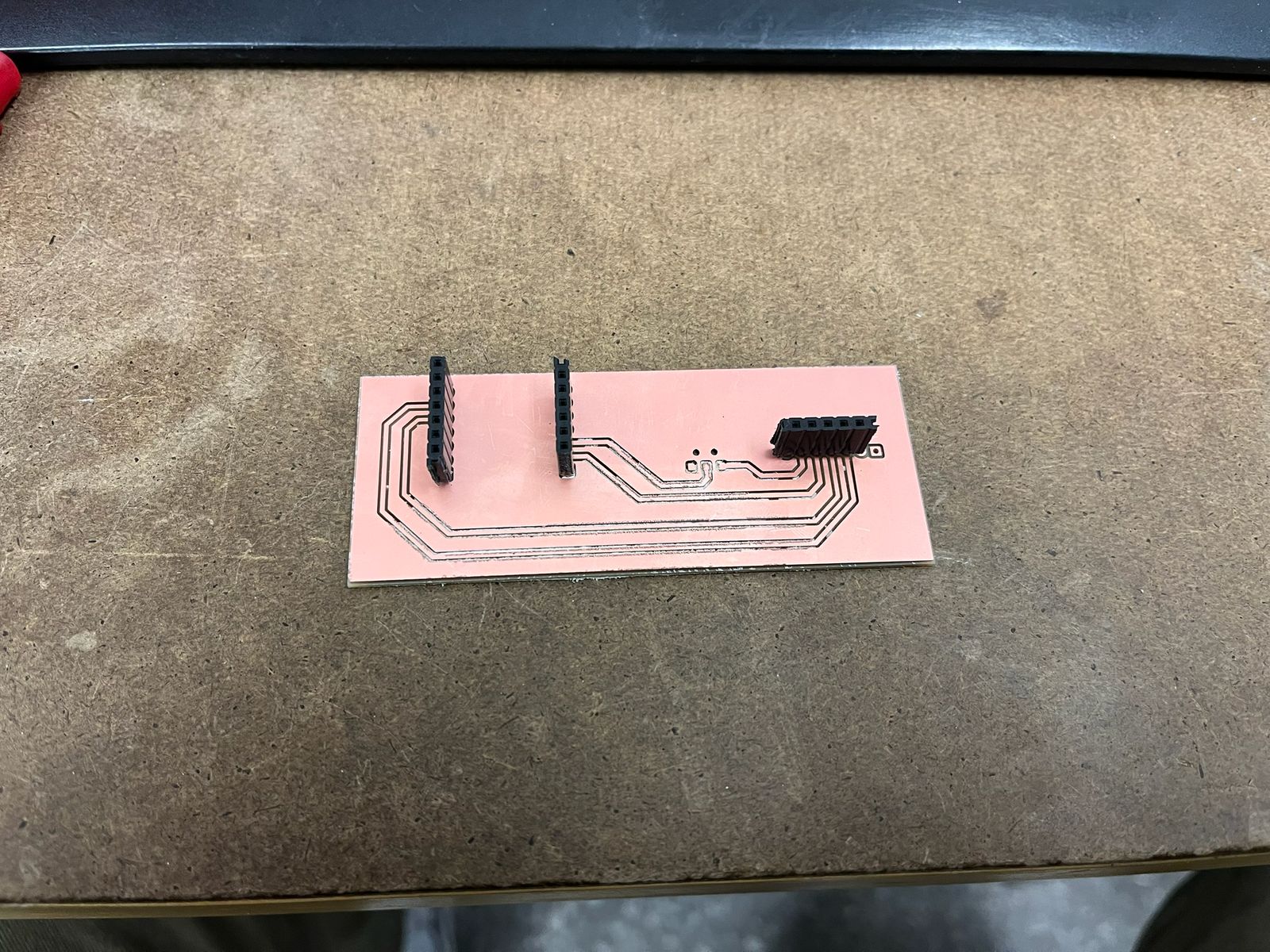
The final product for this would likely include some motion tracking system (LiDAR or CV) to identify a moving object (ping pong balls or something), before using a servo turret to fire a projectiles (Nerf darts). The recitation walked us through an image detection use case of Edge Impulse, an edge model training company that lets you build your custom vision / audio / text models. The class inventory has access to the ESP32S3 Sense, a microcontroller with built-in camera module which I planned to run the edge model on. The PCB design was quite straightforward, as it just included the LiDAR breakout board and the XIAO ESP32 connected via USB-C to my computer. Instead of adding the footprints, I used headers instead to allow for easy use & re-use of the ESP32. It is an expensive component and permanently soldering it to the board would be very inconvenient. With the ESP32S3 coming in at 17.5mm width, I estimated the two header rows to be soldered 16mm apart. The XIAO headers were oriented to point the same direction as the 8-pin header for the LiDAR board and I used Net Labels to determine what pin on each header corresponded to the board pins. I also added a switch in series with the LiDAR scanner as an additional input device.
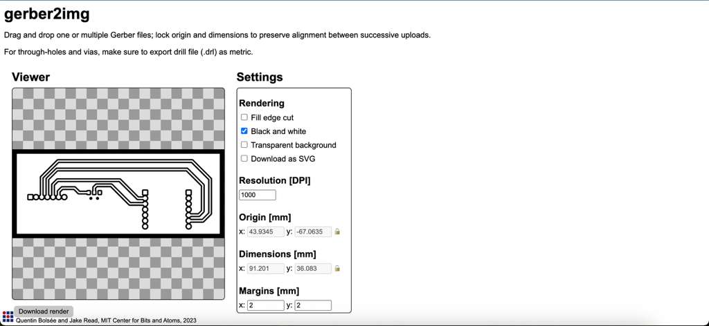
This workflow also required generated Drill files in metric convention to make holes for the headers. I used the gerber2img converter and dragged both the edge outline and header hole files together to create one job for the 1/32" endmill. The mods software calculated the toolpath once again for both jobs.
The machine got to milling and generated the through holes for the headers to go through. I had to distanced everything manually which worked out for the LiDAR module, but the ESP32 headers were slightly too far apart. The holes were still correct size and so I was able to get the board assembled in a patchy way.