Design, mill, and assemble a microcontroller board.
Add an output component to the board and program its operation.
Measure the power consumption of an output device.
Tools
KiCAD EDA
Component Search Engine
Benchtop Power Supply
Modela Mill
Soldering Equipment
Inventory Output Components
Individual Assignment
Design
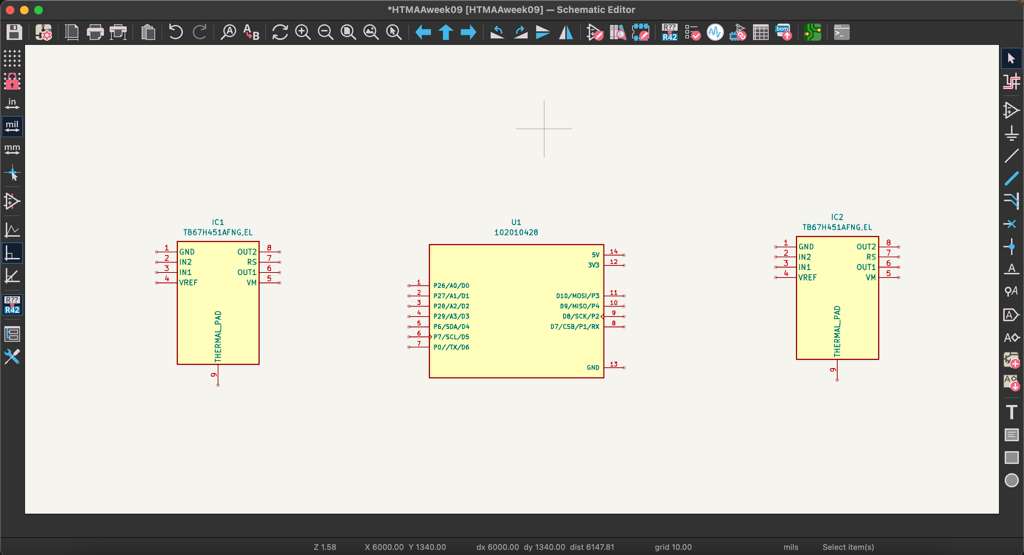
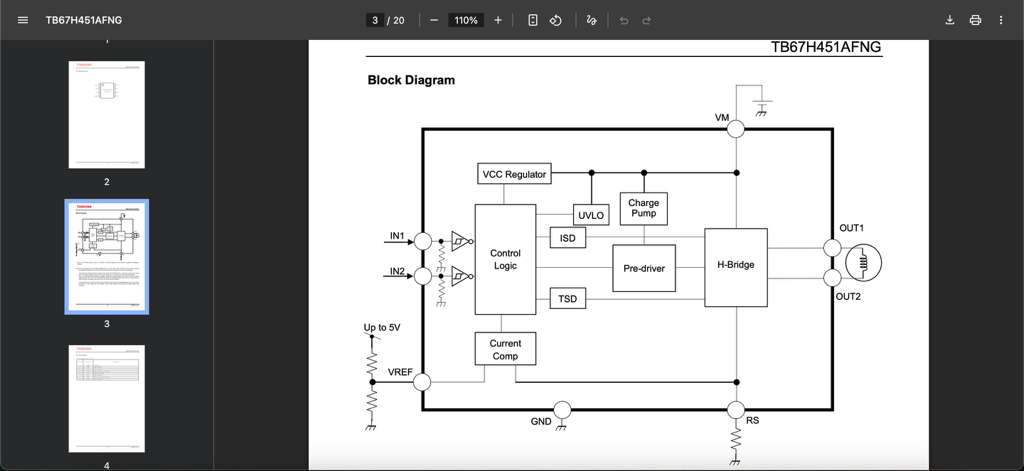
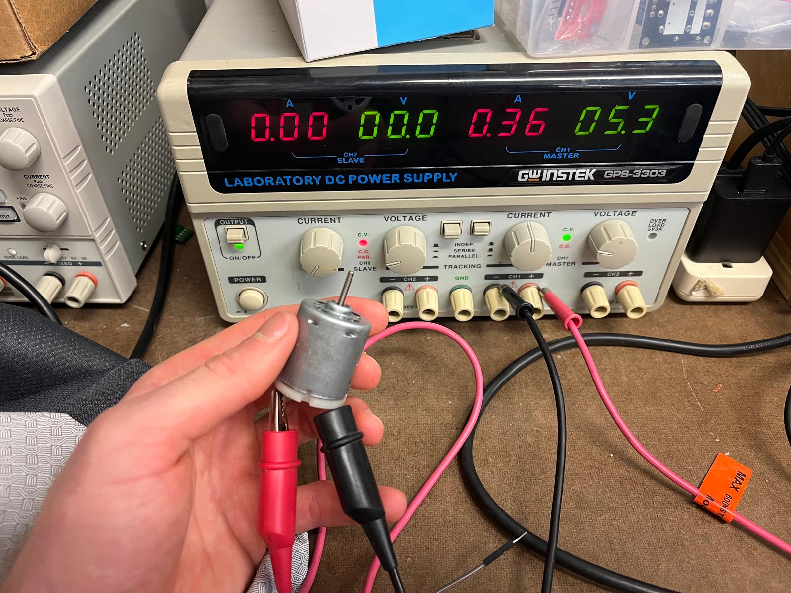
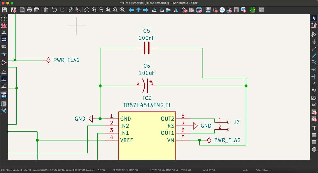
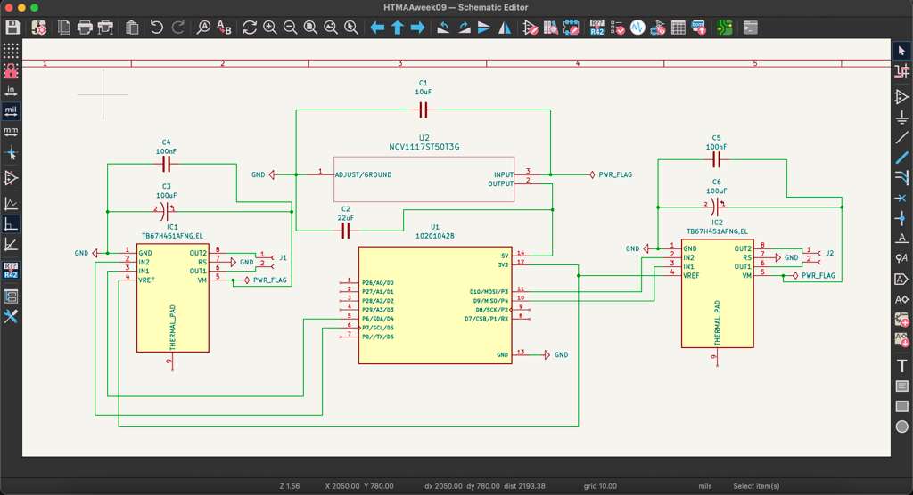
As a logical follow-up to last week's input device assignment, this week we had to focus on output devices. After the Nth final project pivot (this time to an auto-aiming trash can), I decided to focus on driving brushless DC motors for this week. The trash can would need to move quickly in order to "catch" bad throws, so I chose the motors in the inventory with the highest stall torque (for highest acceleration). I opened up KiCAD and started the schematic design, using the XIAO RP2040 to control two brushless DC motors. The motor requires a motor driver (TB67H451AFNG) that connect to two GPIO pins on the XIAO for logic and an external power supply. I followed the datasheet to connect the output pins to the motor and reference pins to the XIAO 3.3V and GND. In my case, I was planning to use the benchtop power supply to drive ~12V through the motor which I tested briefly in the Archshop.
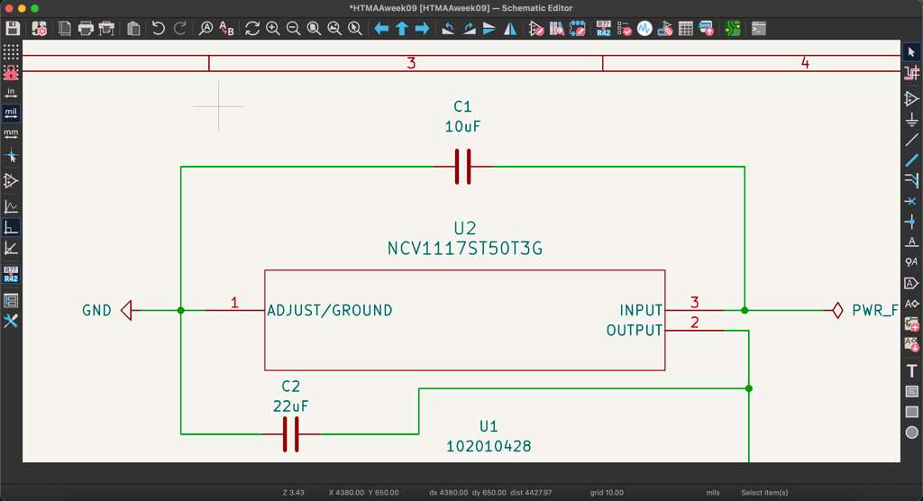
The next step was adding a 5V step-down regulator to power the XIAO because 12V would have destroyed it. I connected the motor drivers and step-down regulator to their respective places on the schematic. The last step before going to the PCB layout was adding decoupling capacitors for the motor drivers and regulator to minimize noise and reduce voltage spikes. The regulator required a 10uF and 22uF ceramic capacitor circuit, while each motor driver required a 100nF ceramic and 100uF electrolytic alumninum capacitor in parallel to handle motor voltage spikes.
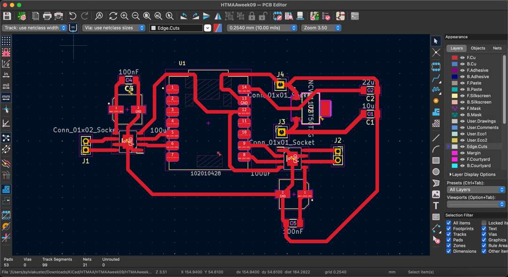
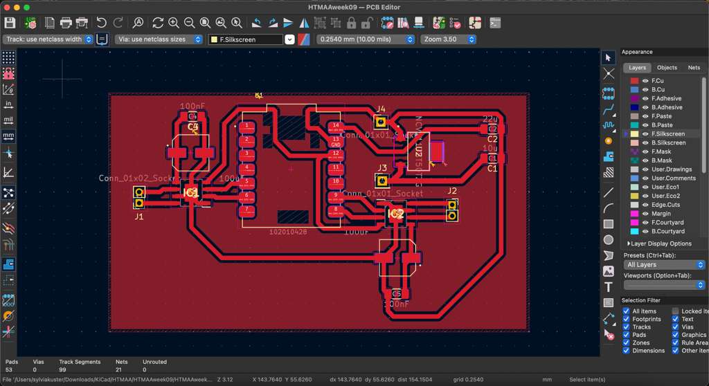
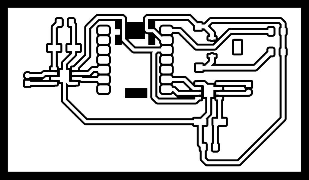
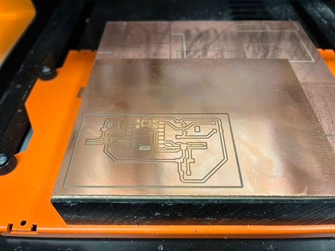
Once the schematic was done, I opened up the PCB layout editor and arranged all the components on the board. I had to make sure the XIAO was oriented with the USB-C port facing the edge, and that the power supply traces were sufficiently thick to carry the +12V load (>1mm). I also added header footprints to solder wires that would connect to the motors and benchtop supply. The PCB was exported as a .gbr file along with the .drl holes and converted into a .png using Quentin's gerber2img converter. The Modela mill is Archshop was turned on, the mods software was programmed, the 1/64" endmill was screwed in, and the tool was oriented at the edge of the board.
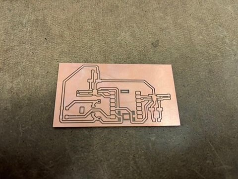
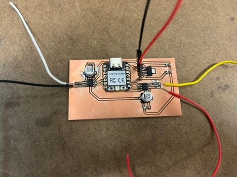
The mill got to work clearing the copper for the traces and using the 1/32" endmill for the edge cut and the wire through-holes. Once finished, I brought it over to the soldering station and finally got comfortable using the magnifying console on the bench. It was surprisingly easy to use and definitely made my soldering more accurate. Also seeing how the solder reacts up close made me understand the concept better and refine my technique. I soldered on the XIAO, the motor drivers, the capacitors, and the wires.
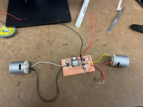
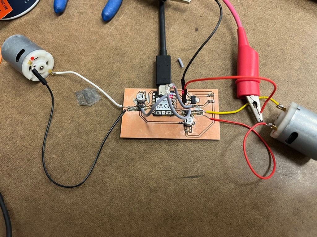
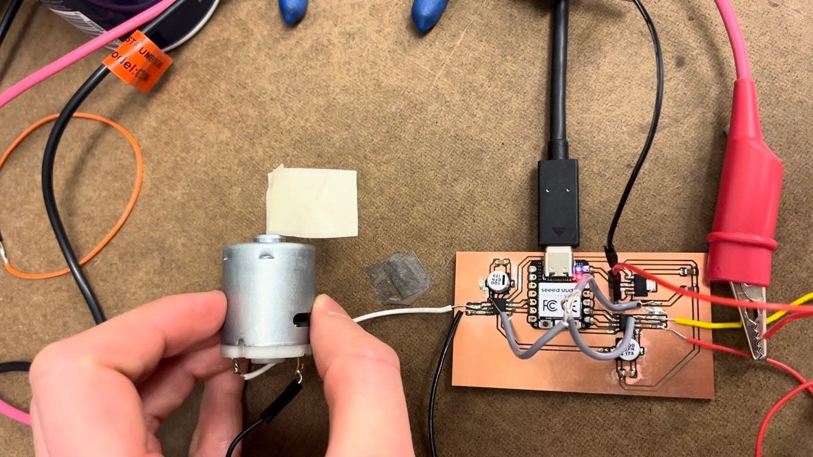
I soldered the board output pins to the motors and programmed the XIAO through my USB-C port. I wrote simple code to test the PWM signal to the motor, including forward, brake, coast, and reverse. The first time through, nothing was working and I was very confused. I double-checked my PCB editor on KiCAD and realized that I had forgotten to lay down the traces for the benchtop +12V power supply. Oops. I devised a DIY easy fix that just consisted of soldering wires across the board to connect the components. Once that was done, I uploaded the code and added flags to the motors to better visualize the motion of rotation.
The motors were working! They were able to alternate states quickly in both directions and stop. This was a successful proof of concept for the trash can drivetrain for my final project, but I might have look into higher power motors for my requirements (and definitely find / make wheels).
This week's group assignment was measuring the power consumption of an output device. With Ryan, we measured the consumption of the stepper and motor driver and then the current pulled by the MCU.