Wildcard week is here! For this assignment, we had an amazing range of processes to choose from. These included:
- Multi-axis Machining
- Waterjer Cutting
- Glass Engraving
- Wire EDM
- Laser Welding
- Textile Embroidering
- NC Grinding
- Laser PCB Engraving
I was very drawn by the welding option, but ended up deciding on the Limits of Laser PCBs session. This was led by Quentin and walked us through the process of making our very own microcontroller boards. Since the beginning of the class, I have been quite fascinated by the nanoscale of modern electronics, and making my own microcontroller board would give me a greater understanding of how these are made.
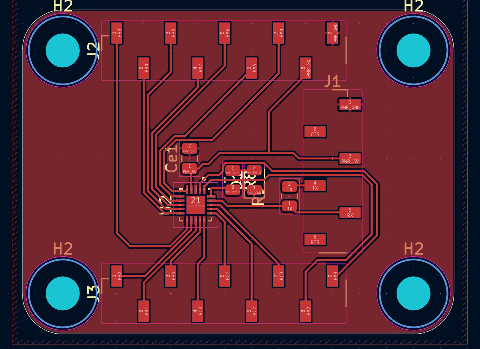
The process began on KiCad, where Quentin walked us through how to design the breakout board. We added our ATTiny 1626 chip, a 6-pin header to flash it, and two 9-pin headers for the GPIO pin breakouts. We also added a resistor LED circuit to test, a 100nF capacitor to provide stable power, and four M3 mounting holes at the edges. The design rules were 0.1 mm spacing minimum, 0.15 mm trace width minimum, 0.15 mm clearance between plane and the rest.
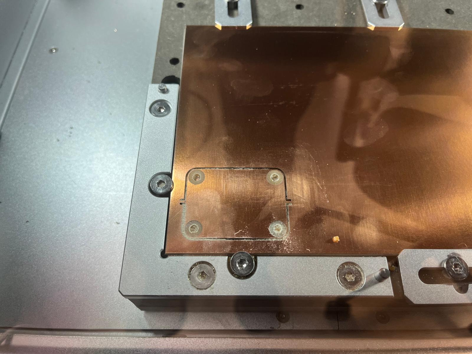
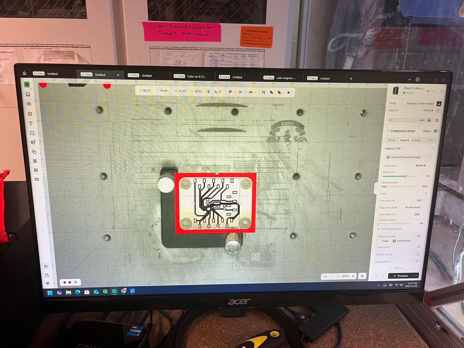
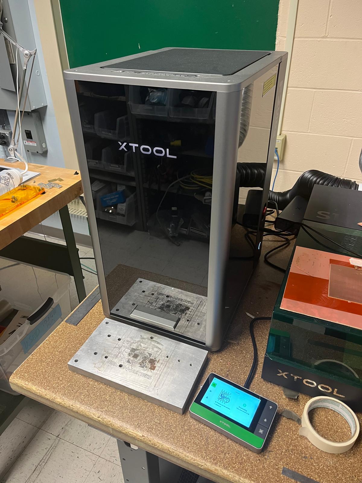
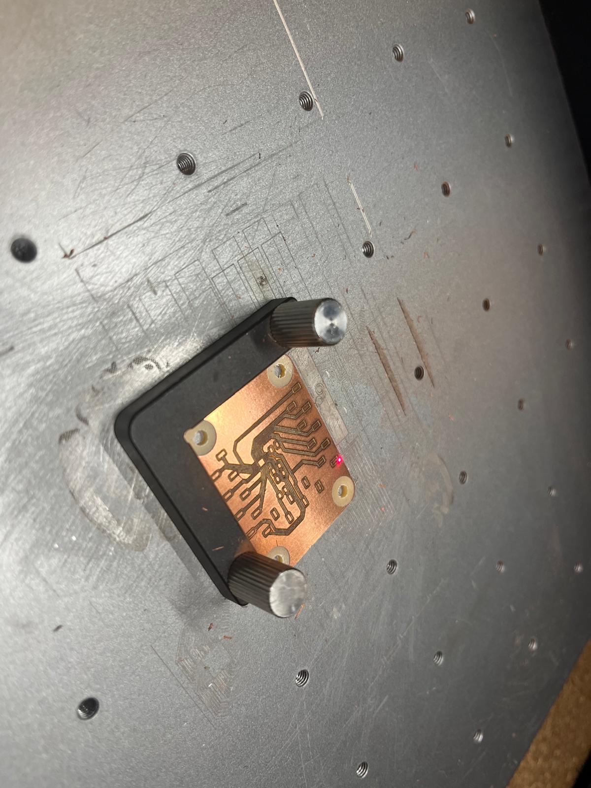
We then took our KiCad design and converted the Gerber file to a png using Quentin's website, adding a surface clearance around the holes to prevent shorts. The design was uploaded to the Carvera mill that created our board outline and mounting holes. Once the board was milled, we brought it over to the very sleek F2 Ultra. This is a laser engraver that can create our tracks / pads on the board at a ridiculously small width.
The beautiful machine below only needed 2 minutes to engrave our circuit, and it came out looking very sleek. Quentin helped us with the first step in soldering by aligning the ATTiny chip on the board and using solder paste and the hot air gun.
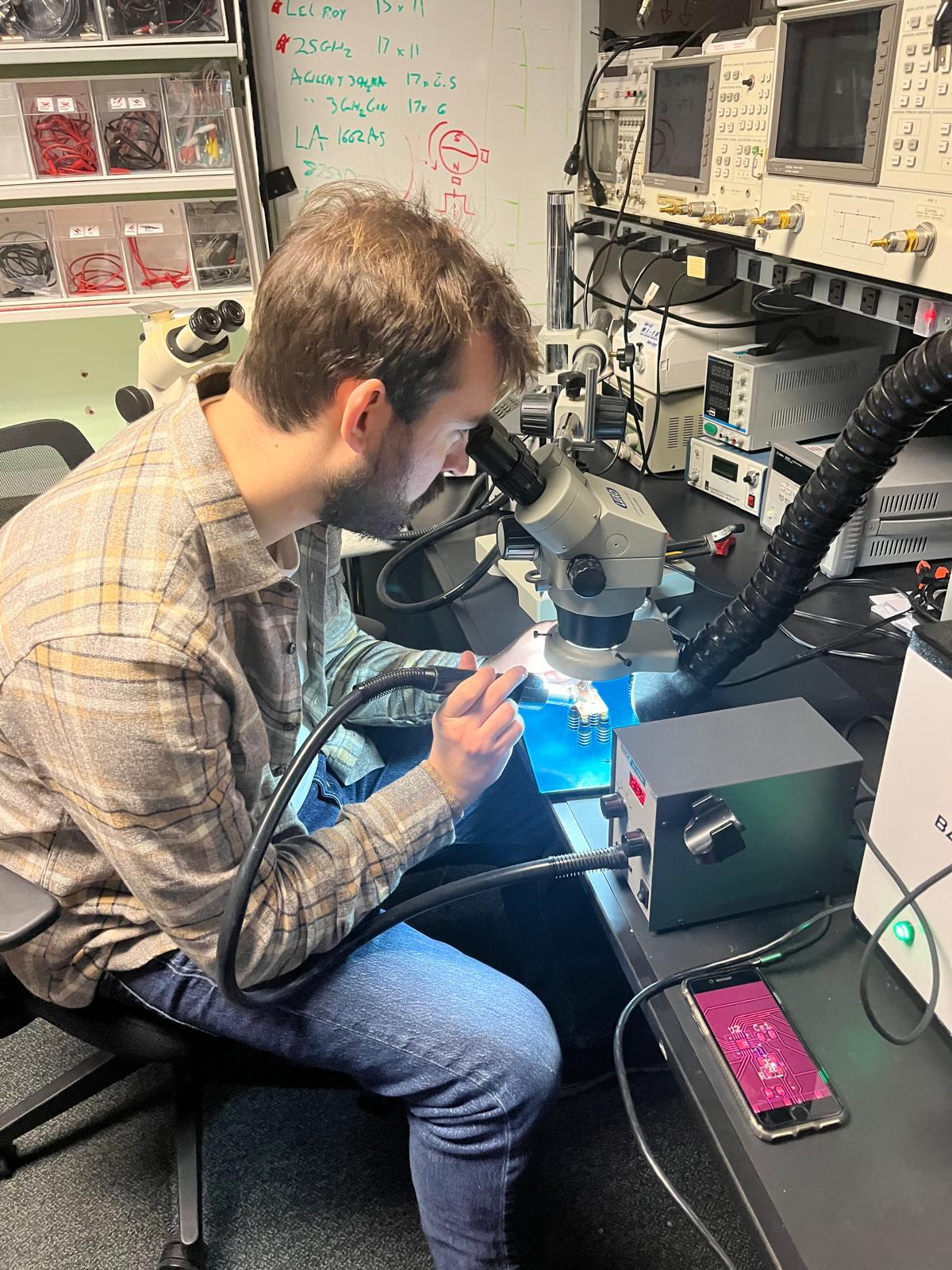
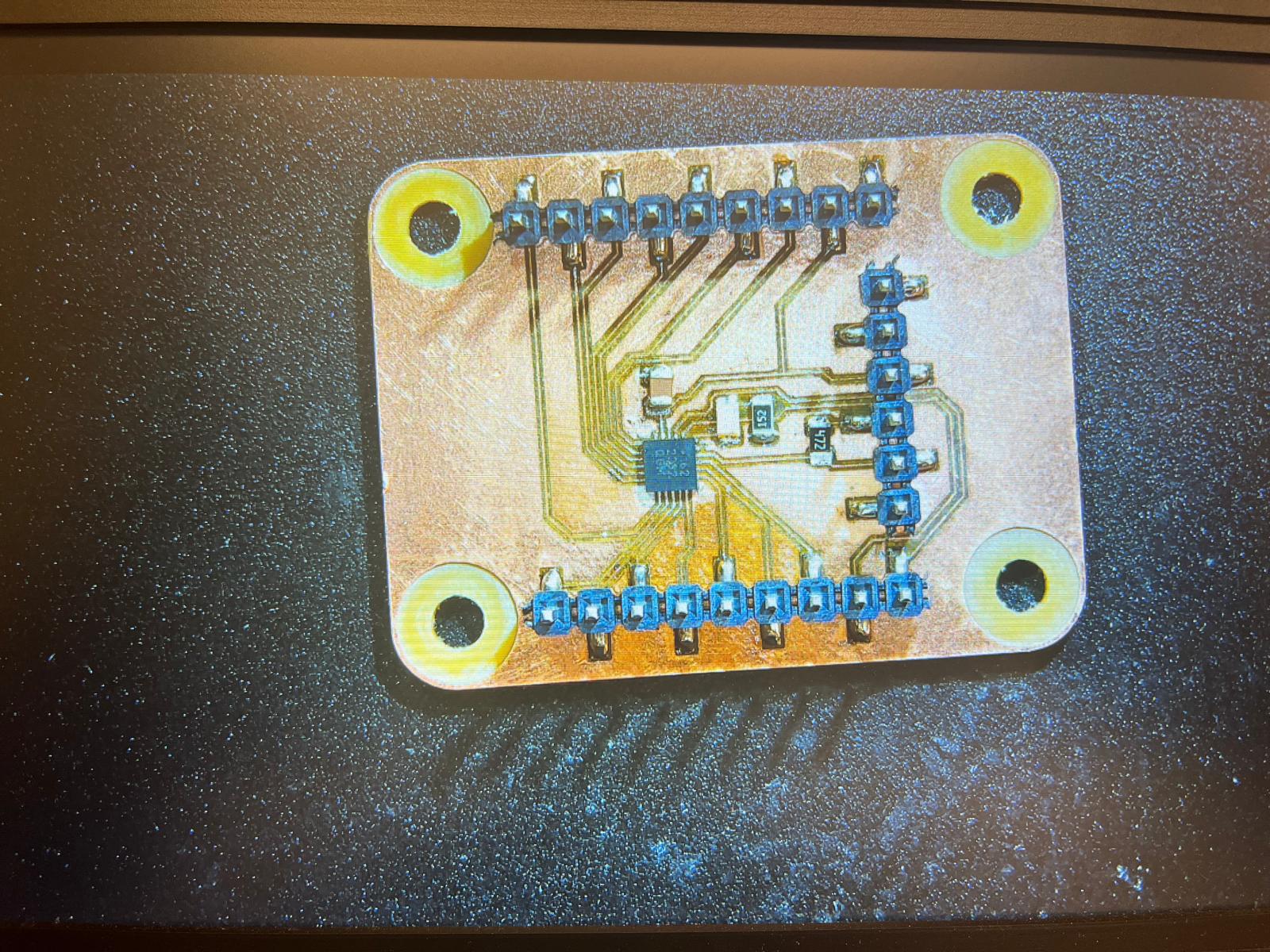
I took the board and necessary components to the Archshop to finish the soldering process. The component sizes were 0805 standard, which can be soldered with a traditional iron. I soldered the connectors first and finished with the resistors, capacitor, and finally the LED. The soldering came out quite clean, except for some of the GPIO pins that had small bridges.
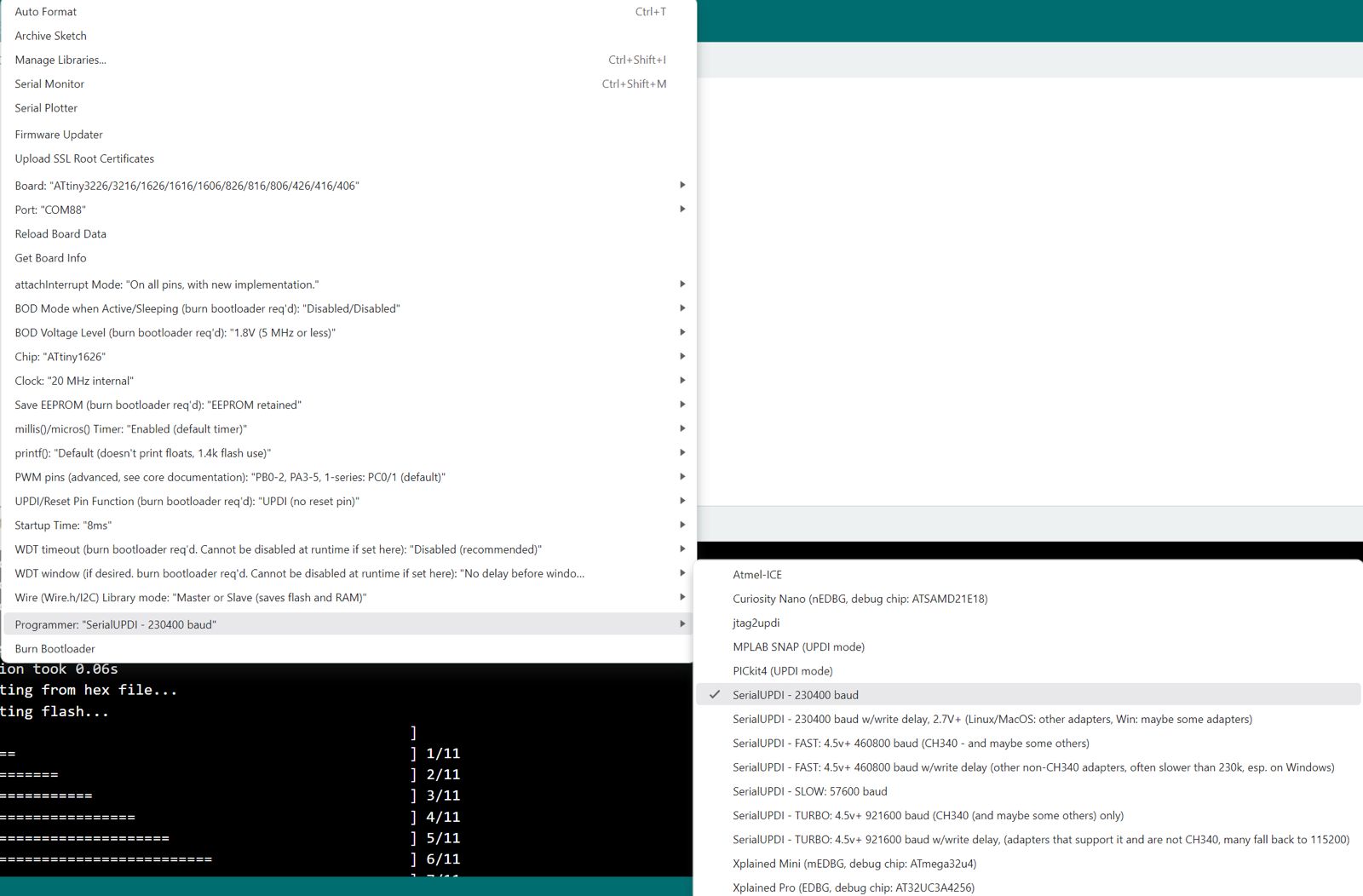
The board needs an FTDI cable to connect to my computer, communicating over SerialUPDI protocol. I connected the board, installed the megaTinyCore board library, and set the right settings to flash the ATTiny 1626 with the FTDI adapter. The board worked! The LED circuit was flashing correctly using the simple Blink program Quentin wrote. We tested the GPIO pins on the breakout and confirmed that a couple had bridges, but still left me with 14+ GPIO pins to play with. Very excited to see how I can use this microcontroller board that I made in future projects! Big thank you to Quentin for his help this week.