Ideas
- 3D priter with additional degrees of freedom for non-planar printing
- Modular robotic system that can snap together, one style of joint
- Telemanipulated robotic arm
I'm not really sure what exactly I want to do for my final project yet, I do think I want it to be some form of robot or tool that is designed with a specific purpose in mind. I don't want to make something just to make something.
10/15/25
I think I have decided that I want to move forward with the idea of making a modular robotics system as my final project. There would be a few main components that I would need to design including a control hub, a drive component, interchangeable gear boxes, and different linkages. The PCB that I made during EDA Development week will be super useful for prototyping for this final project. I do have to revamp it though as I am not sure that the stepper drivers actually work. I plan on redesigning the PCB based off of the model on the class website.
Week 8
It has been a while since I updated my final project page but I have been thinking about it a lot and am ready to make some more concrete goals and
decisions of what to pursue.
I want to start by trying to outline the fundamental goals of my final project so I know just what it is that I am aiming for.
Goals:
I want to design a modular robotic system with two different kinds of actuators. One linear and one rotational actuator. For each actuator,
I want to be able to measure its absolute position using external sensors improving the overall control system and accuracy of the system as a
whole. Additionally, I want each component to be standalone, as in no external wires. I want all of the communication to take place wirlessly and
have power transfer through the joints of the system. As for the controls of the system, I want to be able to control the exact location of the actuators
and if in a system, know the aboslute position of the system. Through software I want to account for potential errors in displacement using the poisition
sensors in the actuators. For example, if a stepper misses a step, I want to be able to detect that and then add an additional step to its rotation to
account for that.
Parts of the project
- Linear and rotational actuators
- Ligaments between the actuators
- Control of individual actuators
- Control of actuator systems
- Communication between actuators
Linear actuator
- Use a ball screw to transmit rotation motion into linear motion
- Use linear rails to support the linear motion from the ball screw
- A platform that enables the connection between additional actuators or ligaments
- Some form of range detection to determine the location of the platform along the linear rails
- Wireless communication
Rotational Actuator
- Use a stepper motor with a cycloidal drive for increased torque
- Magnetic encoder for position detection
- Wireless communication
Ligaments
- Design some kind of universal connection system to be able to connect to actuators
- Right angle ligament
- Straight ligaments
Wireless control of individual actuators
- Reliably send and recieve data between actuator and computer
- Real time position correction. Ie. if a stepper motor is moved or out of position from the last defined position, it moves itself
- Speed control
- Artificial angle limits
Wireless control of mulitple actuators
- Forwards and reverse kinematics of the system for control
- Synchronus motion between multiple actuators at once
- Control from my laptop
There is clearly a lot to acomplish with not much time. I want to start by getting simple versions of the actuators working, without position detection. I think my focus of output devices week will be developing initial versions of both the linear and rotational actuators. This means that I will need to drive a stepper motor, I could continue pursuing the DRV8428 which I will likely do, however, I will simultaneously work with a broken out stepper driver that I have gotten to work before on a bread board enabling me to move forward with design and testing. This will also require me to develop initial 3D models of both the linear actuator and my cycloidal drive. This week I started work on the design of the drive and have used ChatGPT to write a python script to export a DXF of the unique shapes of a cycloidal drive(ADD PYTHON SCRIPT).
Action Items for Week 8:
- 3D model of basic linear actuator
- 3D model of cycloidal drive
- 3D model of rotational actuator
- Drive a stepper motor
- Drive initial versions of the actuators
- Design and make PCB to work with DRV8428
- Drive a stepper motor using DRV8428
Would be nice:
- Do some basic form of position detection on the linear actuator
- Do some basic from of position detection on the rotational actuator
- Communicate something over MQTT
- Drive a stepper motor over MQTT
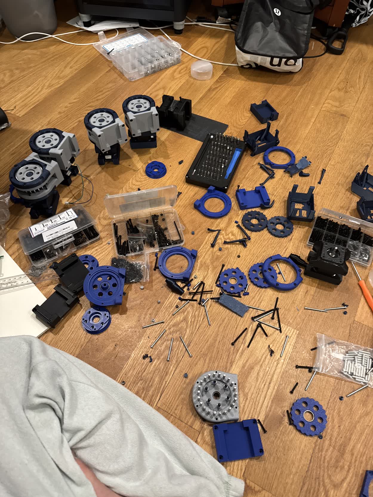
I would say I was pretty successful this week, I have modeled and tested intial prototypes of both actuators! I have yet to drive a stepper motor with the DRV8428 but I have the completed PCB and it is just waiting to be tested. I want to move forward and improve the designs for both. For the linear actuator, I want to add caps to the plates so that they are sapced a fixed distance apart. I also want to build a housing for the motor so it doesn't extend out the back. For the rotational actuator, I want to try and shrink the size of the cycloidal drive and add bearings so that it is a much smoother motion. I would also like to try and begin experimenting with sensor feedback for each of the actuators
Week 9
This week is about molding and casting. I am planning on going away Saturday through Monday morning, so I will have to prep the design that I want to mold while I'm away
so I am able to cast it once I am back. The maker space on campus that I am a mentor in has a whole casting setup so I plan on doing all of the molding and casting there. I'm not
quite sure what it is that I want to cast though, perhpas it should be the cycloids for the cycloidal drive as they would likley have better structural/mechanical characteristics then
a 3D printed counter part.
Regarding forward progress on the final. I need to get a DRV8428 working this week and driving a stepper motor. I also wnat to get sensor feedback from both the magnetic encoders
and LiDAR. I also want to add a limit switch to the linear actuator to serve as a zero point. I can then use the lidar to measure the offset from taht limit switch and then define a modifier
and adjust all of the measurements with said modifier.
For the rotational actuator, I want to design a new version of the cycloidal drive that is smaller and uses bearings to reduce the friciton between the printed components.
Action Items for Week 9:
- Design a model use to create a mold
- Cast using the mold that I created
- Add caps and a motor housing to the linear actuator
- Add a limit switch and LiDAR ranging for linear actuator position detection
- Design a new Cycloidal Drive that is much smaller and uses bearings
- Experiment with the magnetic encoder
- Try to mount a magnet to the back of the stepper motor
Week 10
Unfortunatley, I hardly got anything done this week because I went away for the weekend and was not as productive as I should have been when I was here. With that being said, that means that
a lot of the things that I wanted to do last week carry into this week. I am interested though in exploring what it would take to fully cast all the parts for my cycloidal drive. One I think
that would be incredibly satisfying and I also think that it would improve its reliability and resilience long term.
Action Items for Week 10:
- Design a model use to create a mold
- Cast using the mold that I created
- Add caps and a motor housing to the linear actuator
- Add a limit switch and LiDAR ranging for linear actuator position detection
- Design a new Cycloidal Drive that is much smaller and uses bearings
- Experiment with the magnetic encoder
- Try to mount a magnet to the back of the stepper motor
Midterm Review
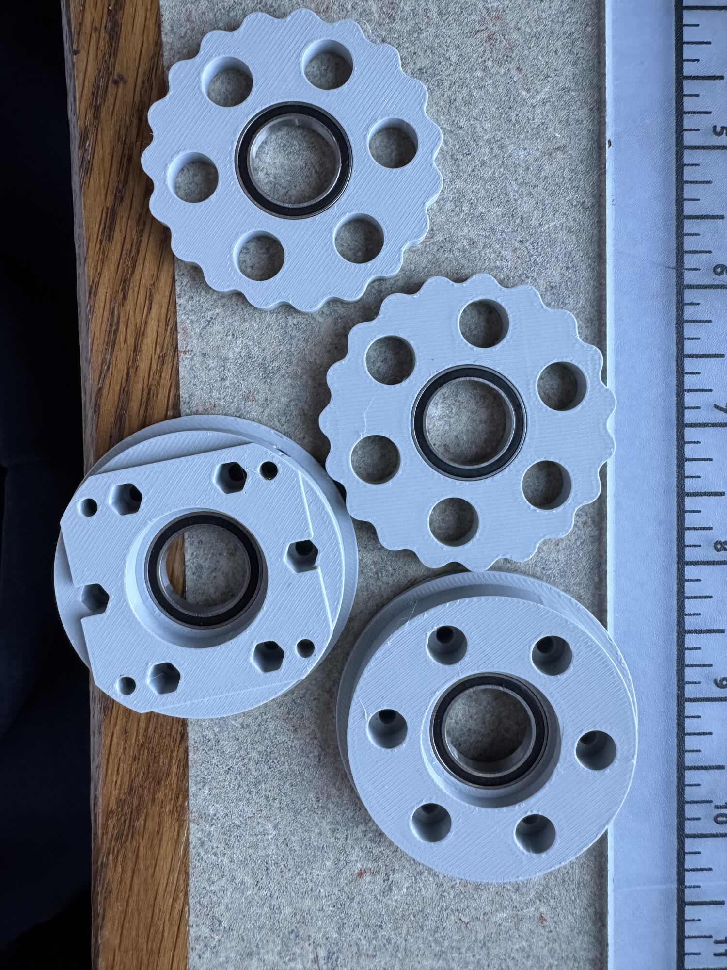
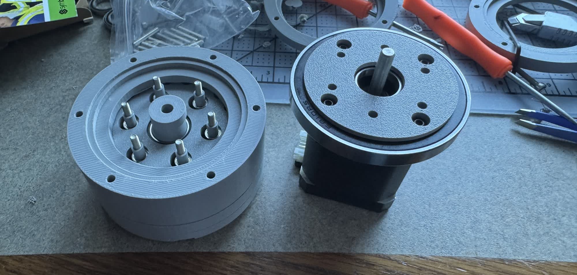
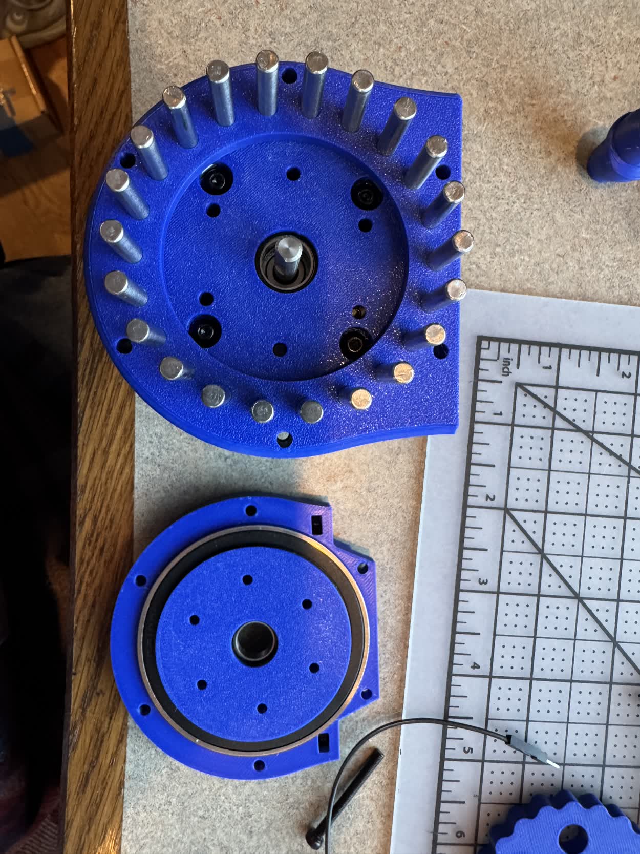
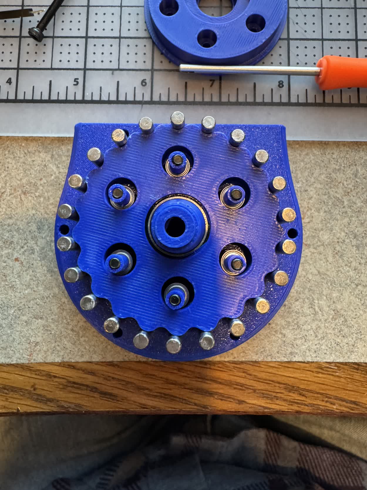
I finished the design and assembly of a refined cycloidal drive. I have yet to power it on, but it seems to run smoothly when I was putting it together and spun the axle myself. I was also surprised that I was able to backdrive it. I don't think I could last time as it was all 3D printed and thus there was a lot of friction between the parts. Now, however, there are steel rollers, and bearings which contact all the 3D printed components instead which I'm sure reduces a ton of the friction.
To Do- Design the connection system
- Modify the linear actuator so that it is more robust
- Add the ranging to the linear actuator
- Add limit switch to linear actuator to enable homing
- Design desired control system for the linear actuator
- Add a magnetic encoder to the back of the cycloidal drive
- Add a limit switch system to the cycloidal drive (potentailly instead of encoder)
- Design desired control system for the rotational actuator
- Figure out wiring between the systems
- Design PCB for each actuator
- Figure out MQTT protocol/commmunication between MCU
- Build base that actuators connect to
- Communicate desired position of actuators from computer
- Design and example bot with inverse kinematics
Schedule
Week 11 (11/19-11/25): Networking and Communication
I think this would be a perfect opportunity to try and figure out the MQTT communication protocol which I want to use to communicated between the individual actuators. In order to do that, I would like
to have functioning, if not finalized actuators to communicate to. The rotational actuator is close, I think I will only need one more rendition of it where I will add the limit switch for homing. For the
linear actuator, I think I am slightly farther away, I need to make the design more robust, add homing and poisition detection.
Goals for the week
- Design the PCB for both actuators
- Finalize the design for individual actuators (don't need to worry about connection yet)
- Test actuators and make sure that they have enough torque to do what is desired
- Be able to communicate between the actuators and my computer
I think this week can be used to work on a more generalized communication for the actuators and how the user can control multiple simultaneously. Also great to determin what controls the user will have over the system.
Part of this, I think will need the actuators to begin being connected. As I'm writing, this, I am remembering that this is the week of Thanksgiving where I am going to be out of town. With that being said, I think it
is the perfect opportunity to design the connection system and control interface with the actuators. Also, if the communication wasn't finalized last week, polish that up this week as well.
Goals for the week
- Design the control interface for the actuators
- Finalize the design for the connection interface and wiring system
This is wildcard week, I'm not sure I can think of anything in particular that I would need to learn. I think that the control system will likely become the hardest part of the project and so if I need more time for that,
I'll have some here. Also this would be a good time to make a few more of the rotational actuators or connection units.
Goals for the week
- Have all of the actuators that I am going to need for my presentation
- Integrate the communication system and the actuators IRL
- If extra time, perhpas design and make an end effector
I think this can serve as a catch all week for when the project inevitably doesn't go to plan or something takes more time than neccesary. This will also serve as a good time to refine my website and prepare my final presentation. Goals for the week
- Polish up any lacking areas of the project
- Prepare my final presentation
- Build demo and make sure that it works
System Diagram
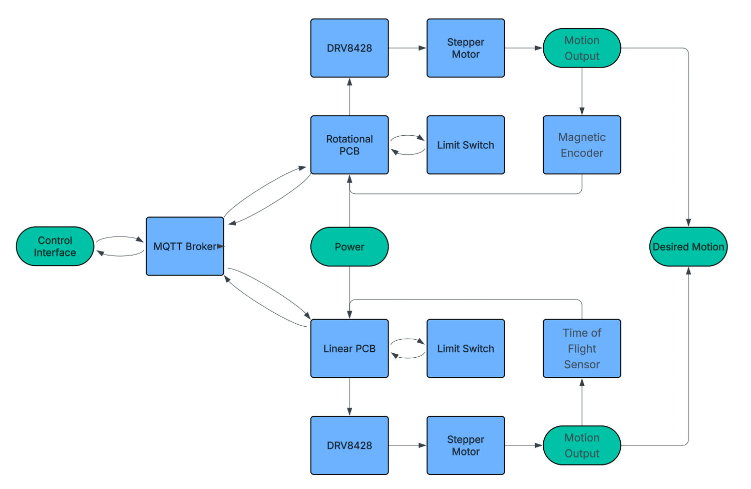
This only shows one of each kind of actuator, but there may be multiple rotational actuators in one of the actual examples.
Week 11 Progress
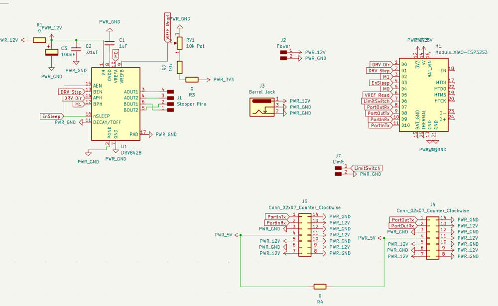
There were a bunch of different asspects of the project that I wanted to work on this week. After my conversation with Anthony, I felt comfortable jumping
into making the schematic for the PCB
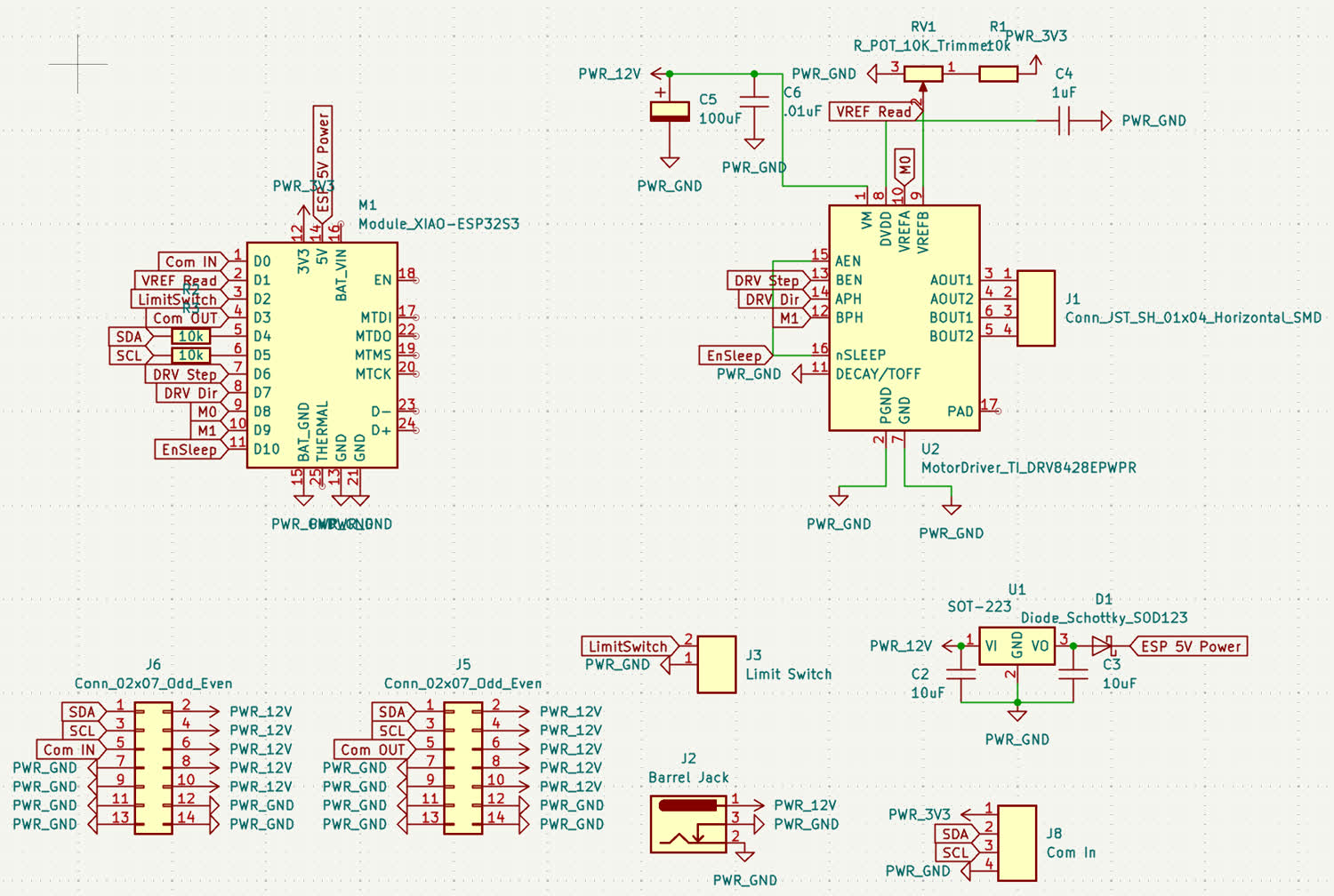
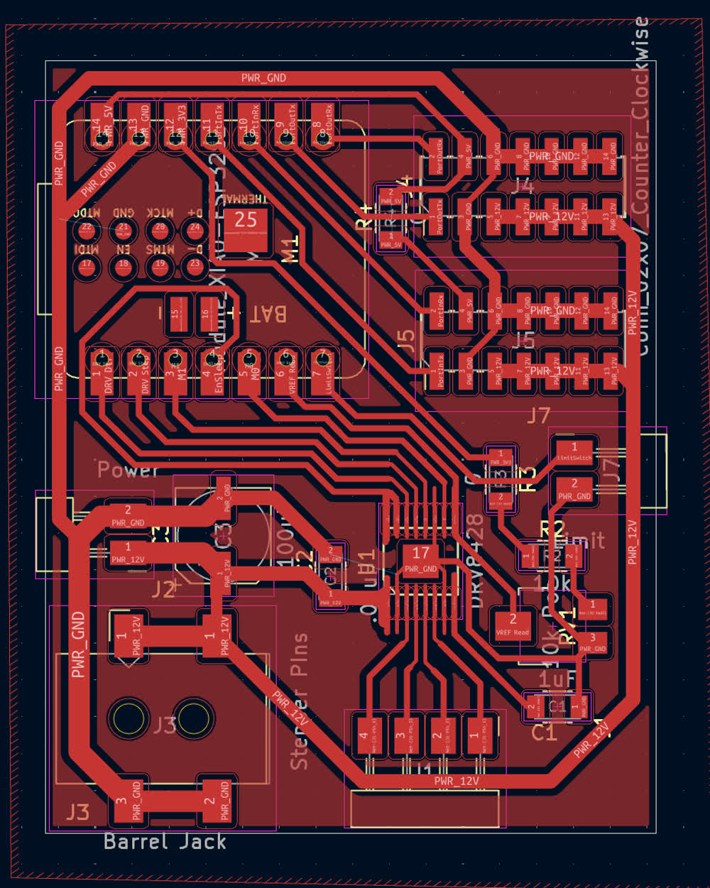
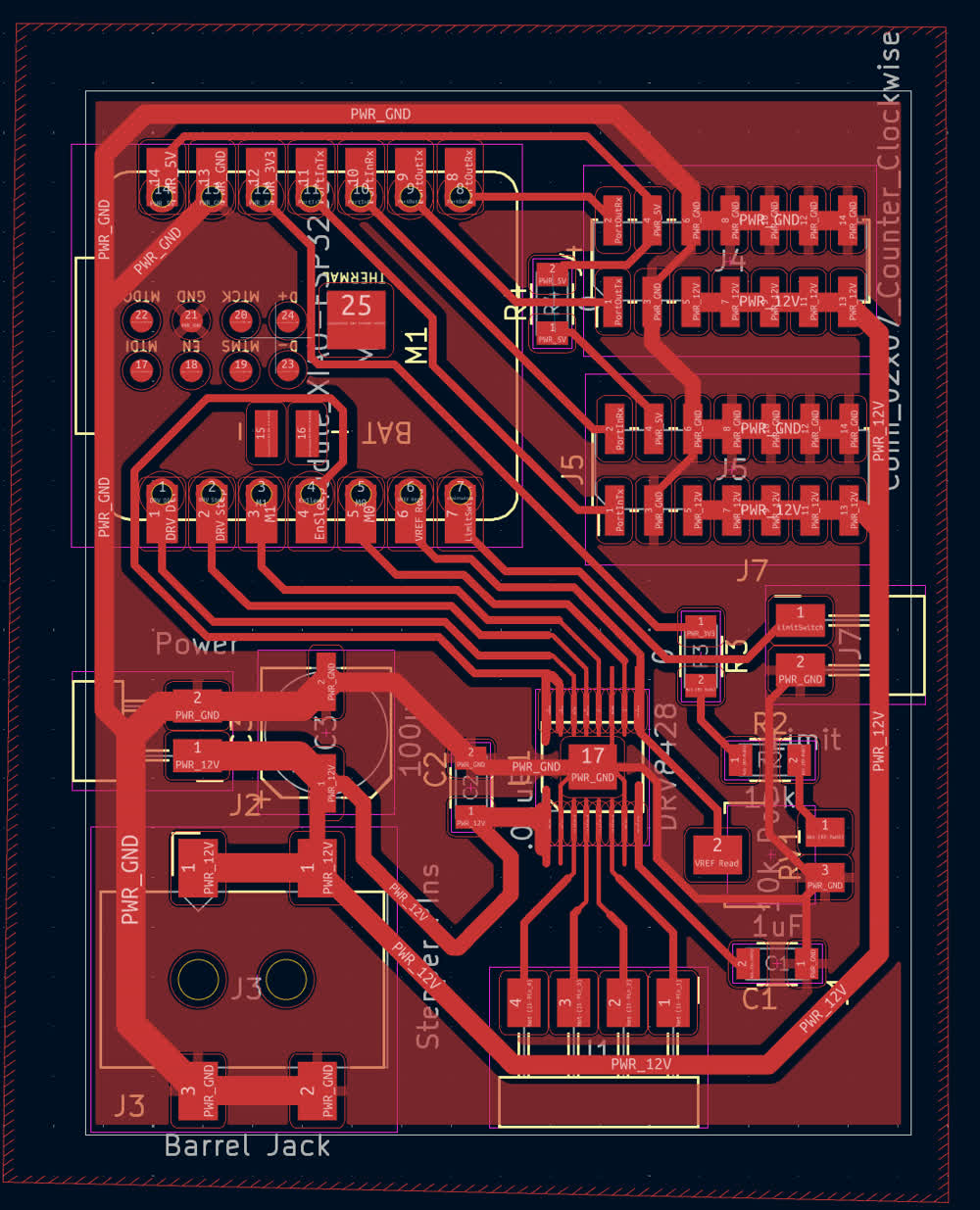
What is nice about this design is that it will work for every actuator in the system, linear or rotational so my plan is to make a prototype and once
that is working, send it out to a board house to make higher quality versions. Unfortunatley, I didn't get a chance to mill the PCB before I left
and so I am starting to get pretty stressed about whether or not I'll be able to get everything done and working in time but I still have some time.
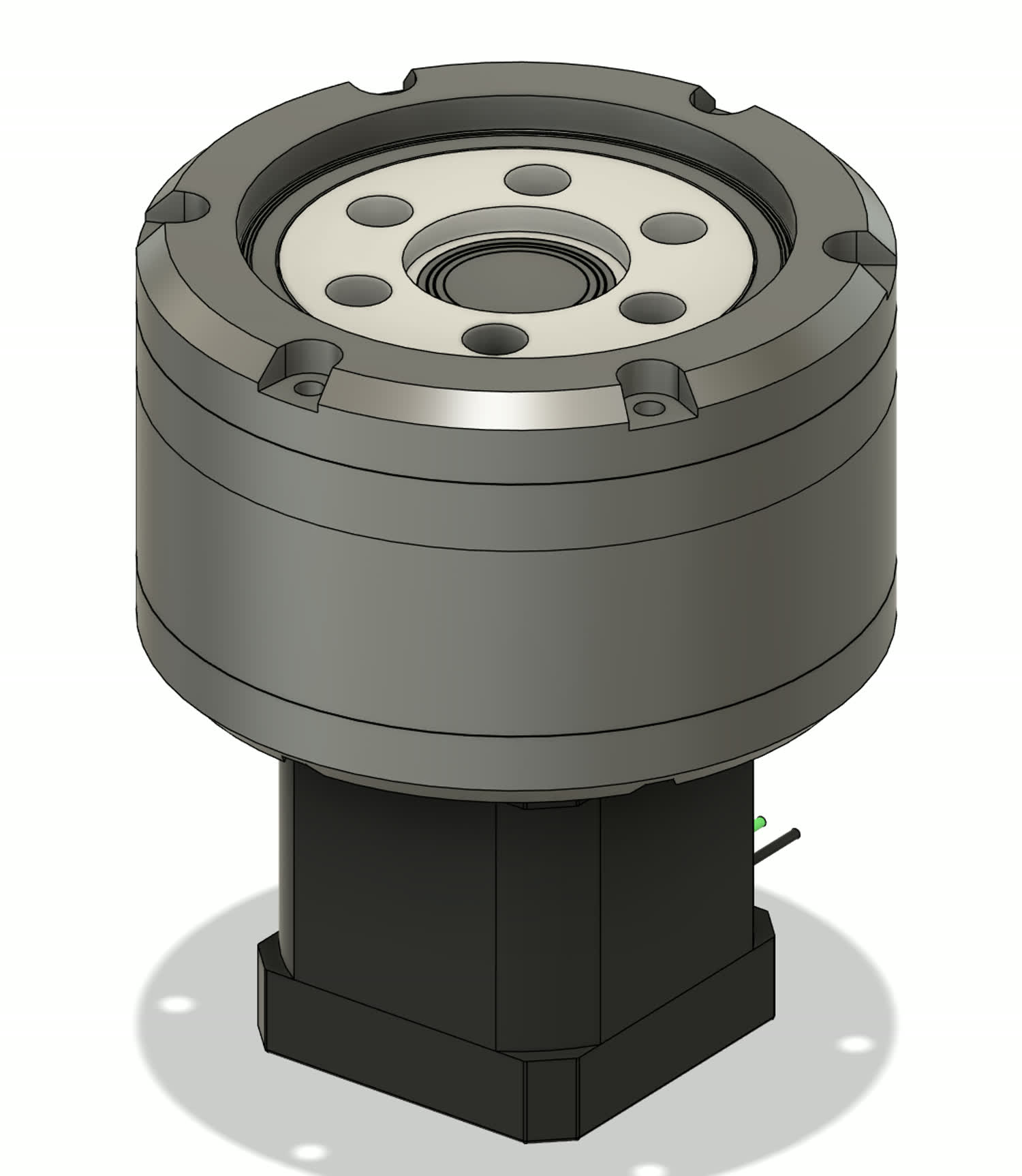
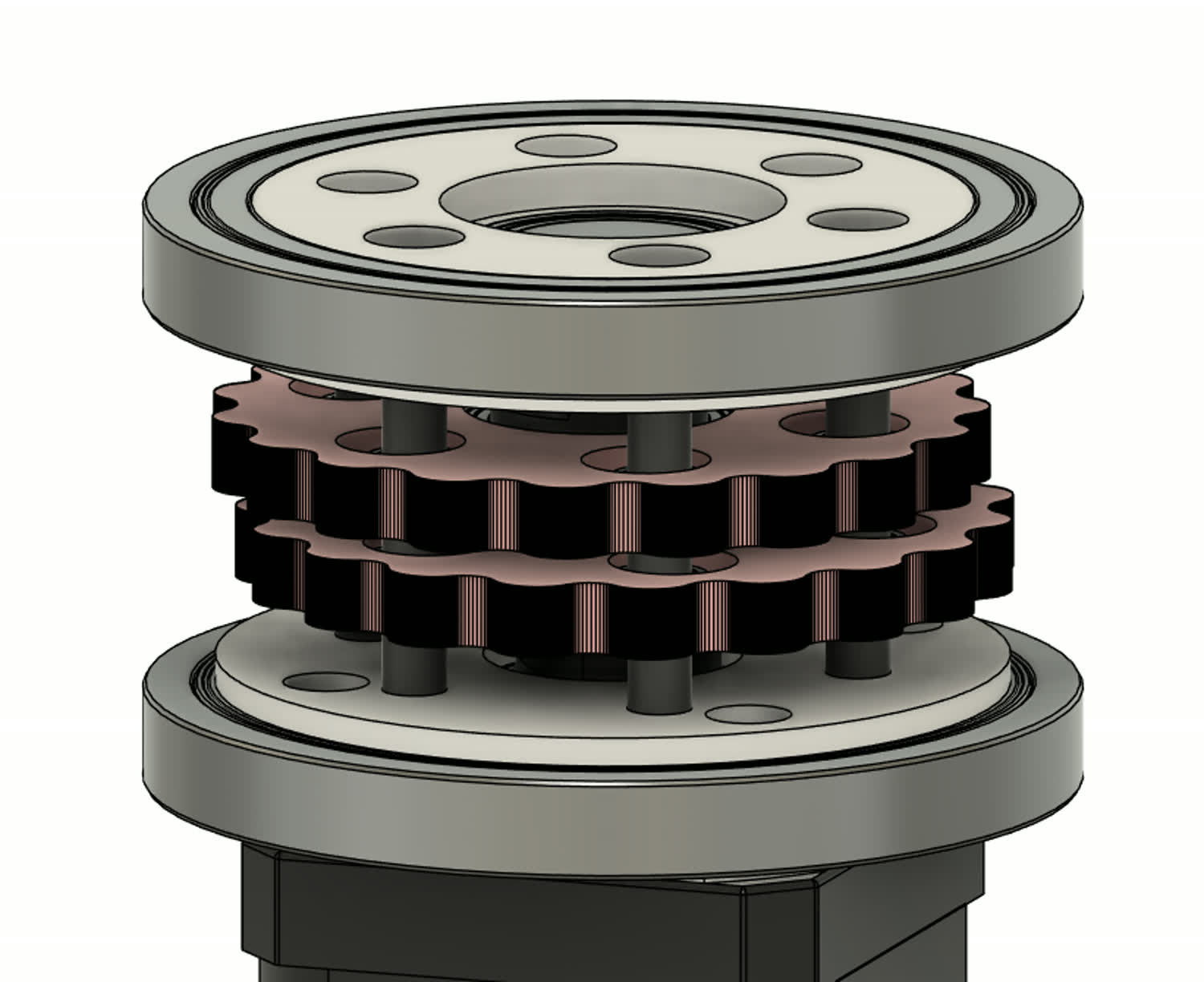
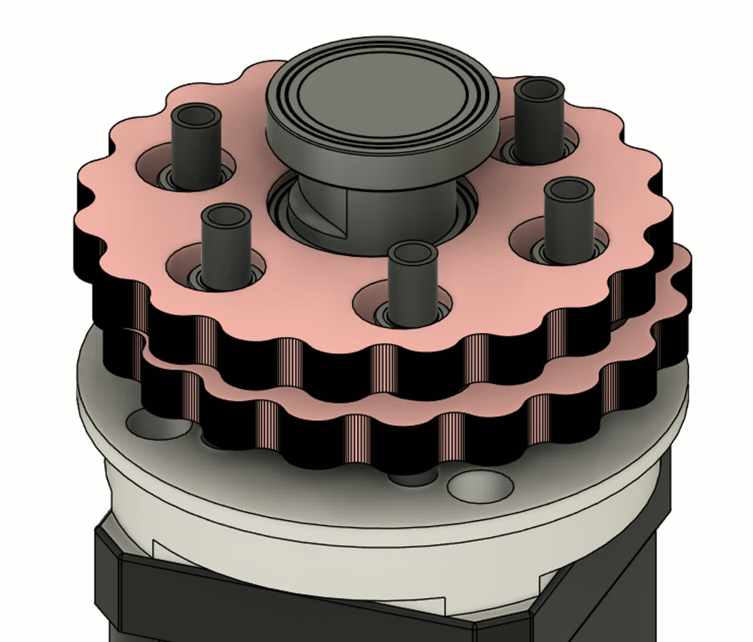
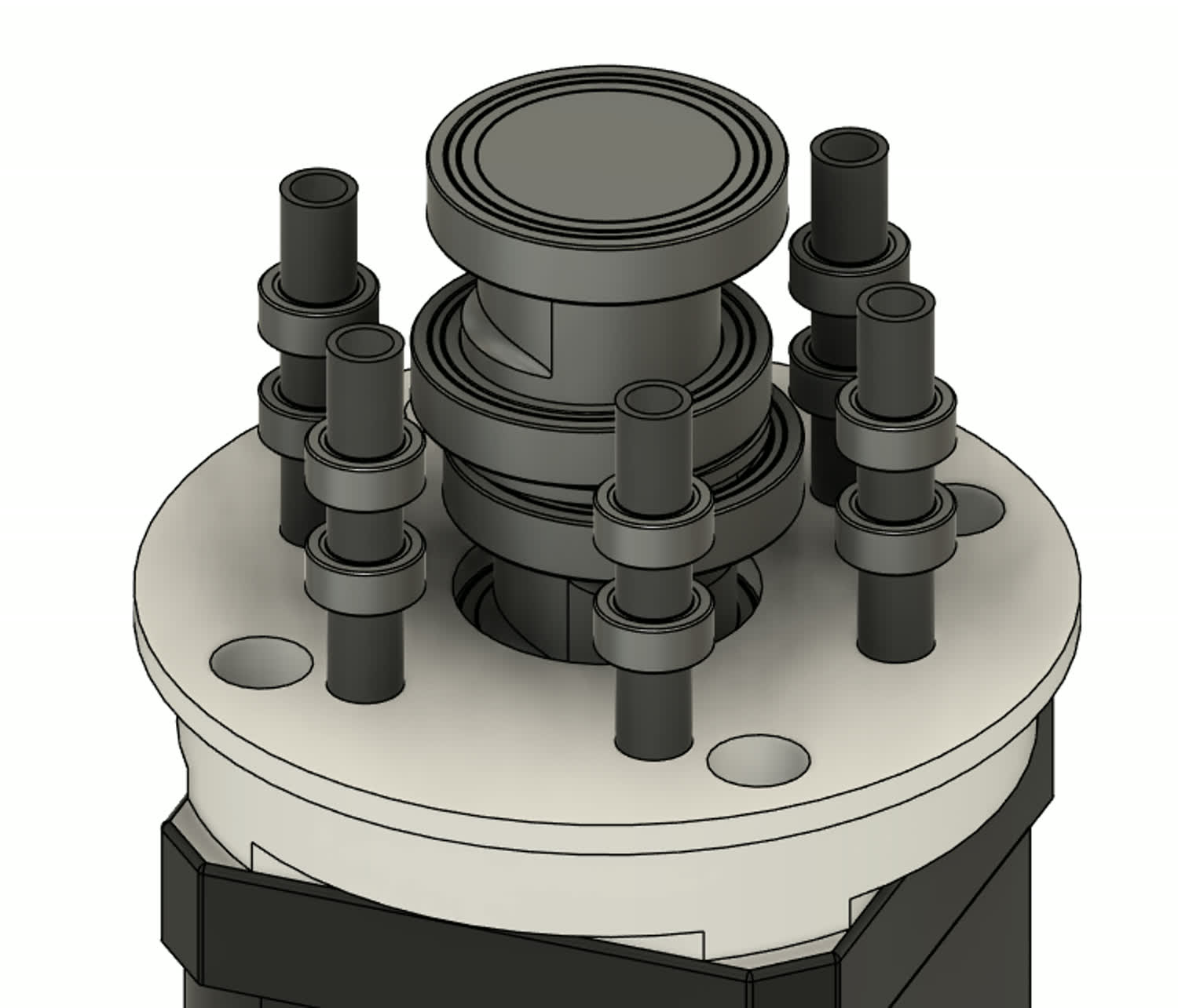
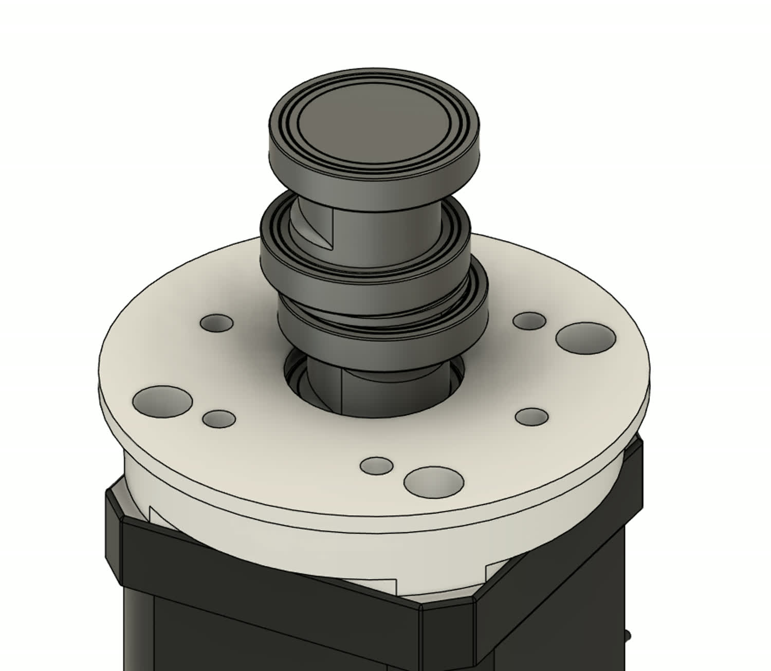
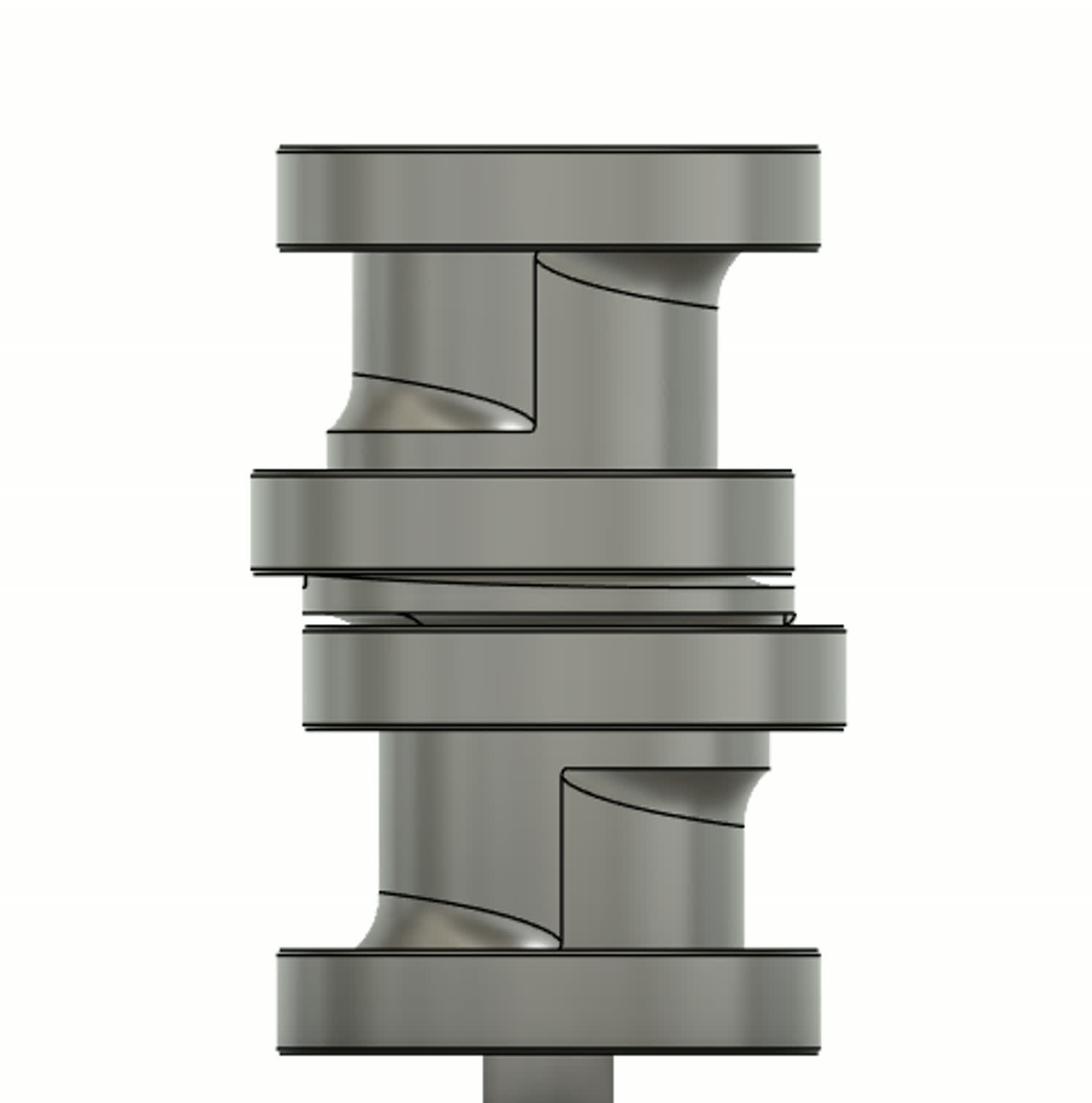
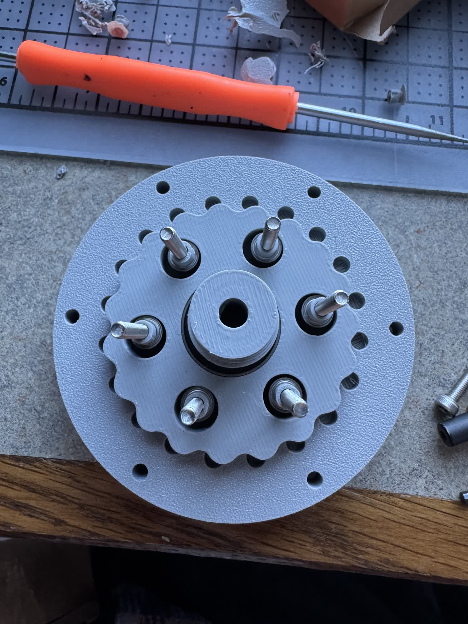
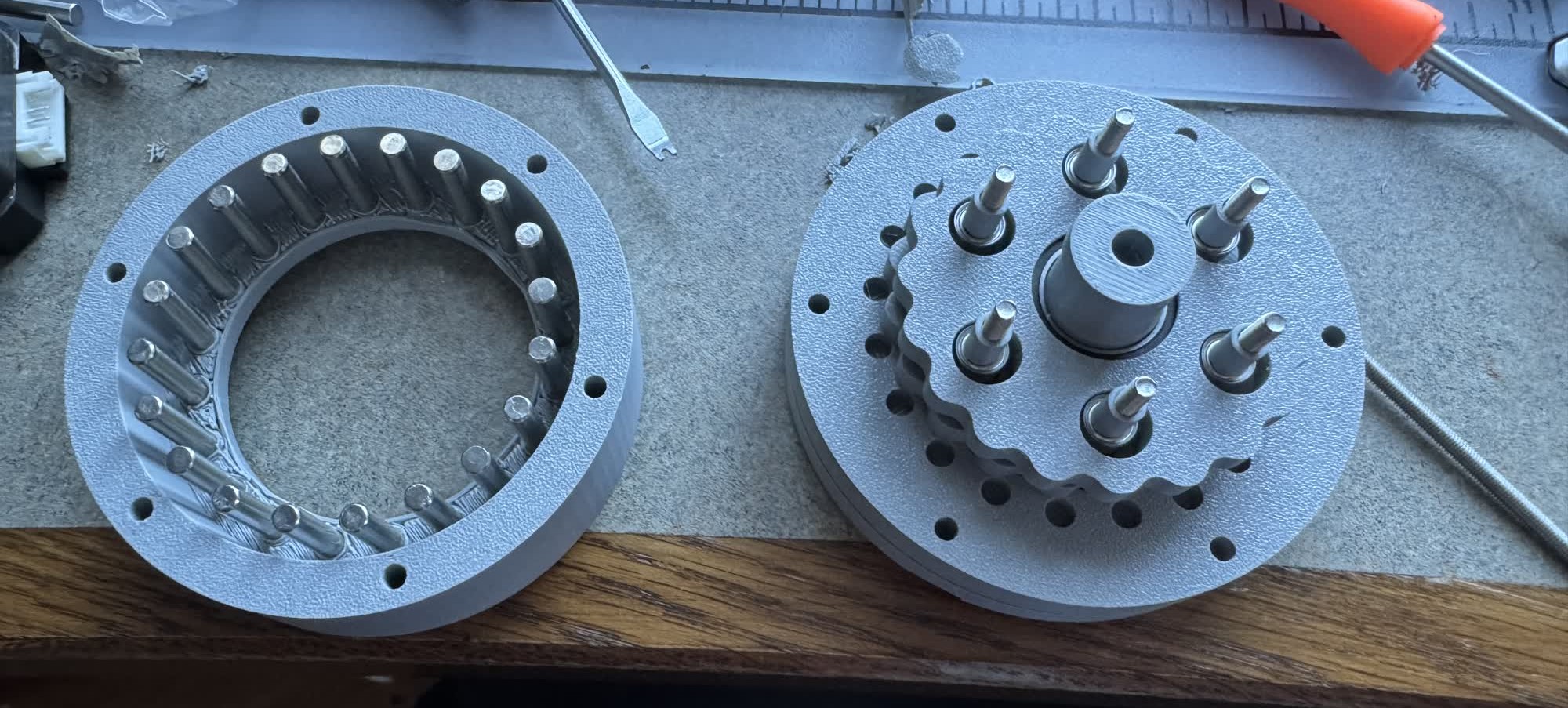
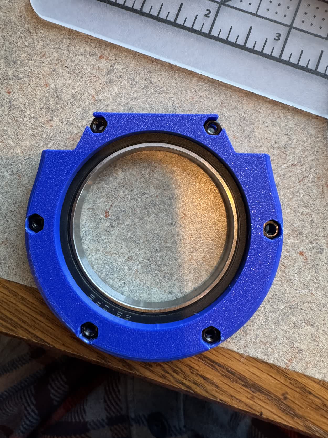
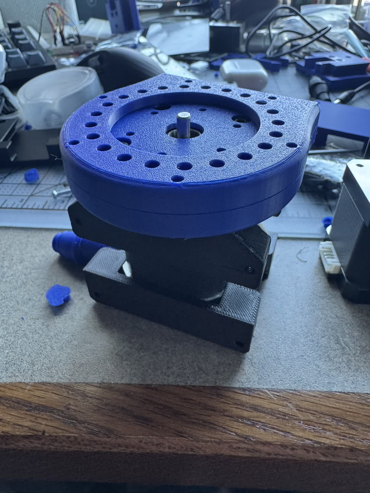
I finally got the opportunity to test the cycloidal drive that I designed and assembled last week, I don't think I included the documentation for it there
so I will include some here. The goal was to make a far more robust drive with less friction by including proper hardware so steel pins or bearings.
To start, I again used the python cycloid generator that chat made to generate a new cycloid DXF to design around. I will include a link so that you can
download the generator yourself. Here was the command that I used.
INSERT PICTURE OF COMMAND FOR THE CYCLOID
INSERT PICTURE OF GENERATOR OUTPUT
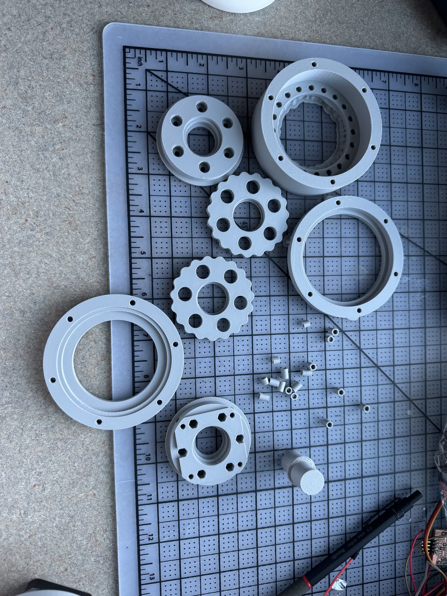
I then spent sometime on amazon trying to find the different components that I would need for the design and I ended up deciding on these different parts.
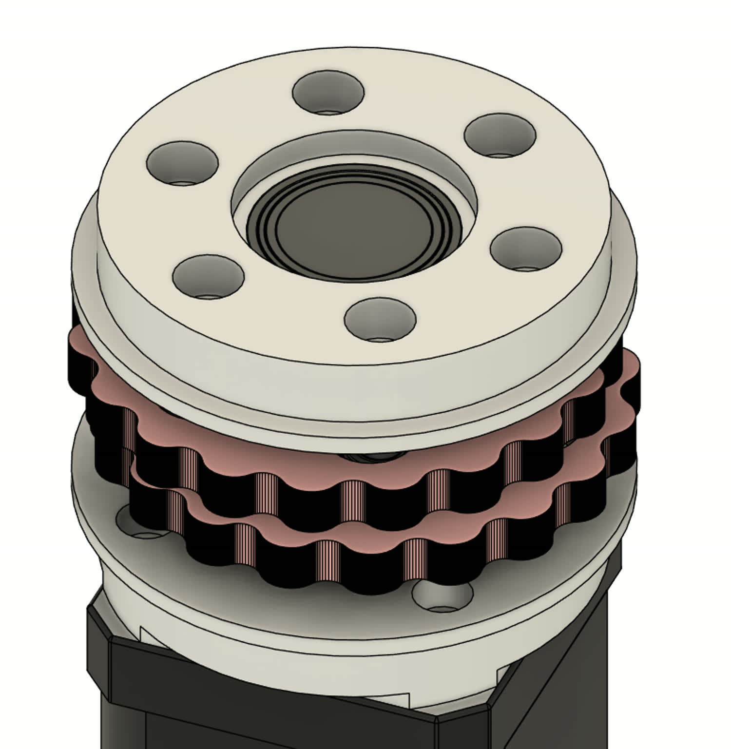
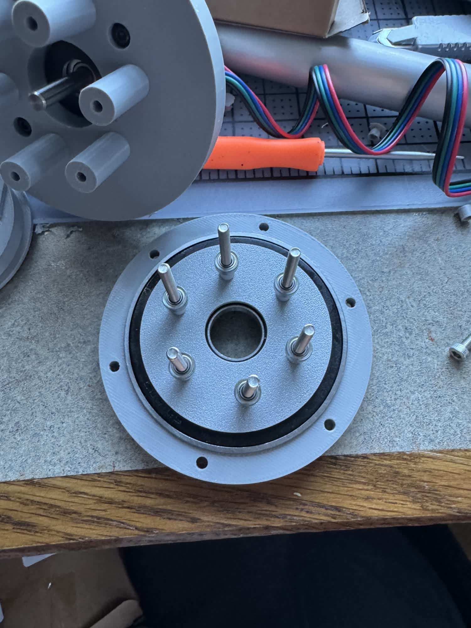
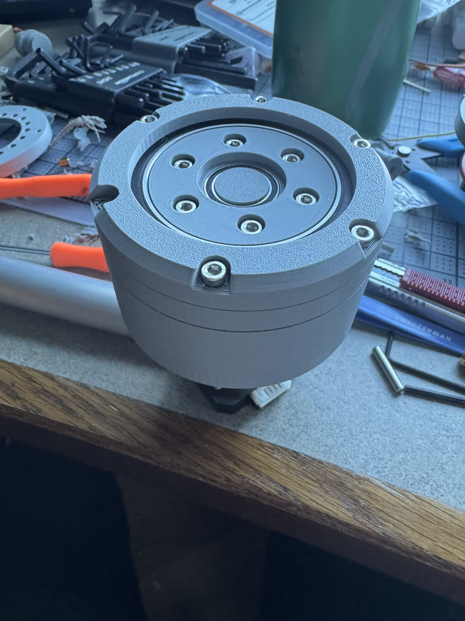
I was super excited to see it working, I was a little nervous that it started stalling but I think I just need to play with the current limiting and do some more robust tests to just make sure that it has more than enough torque to do what I want. In theory it has 11 Nm which is plenty but I don't want to just bank on that.
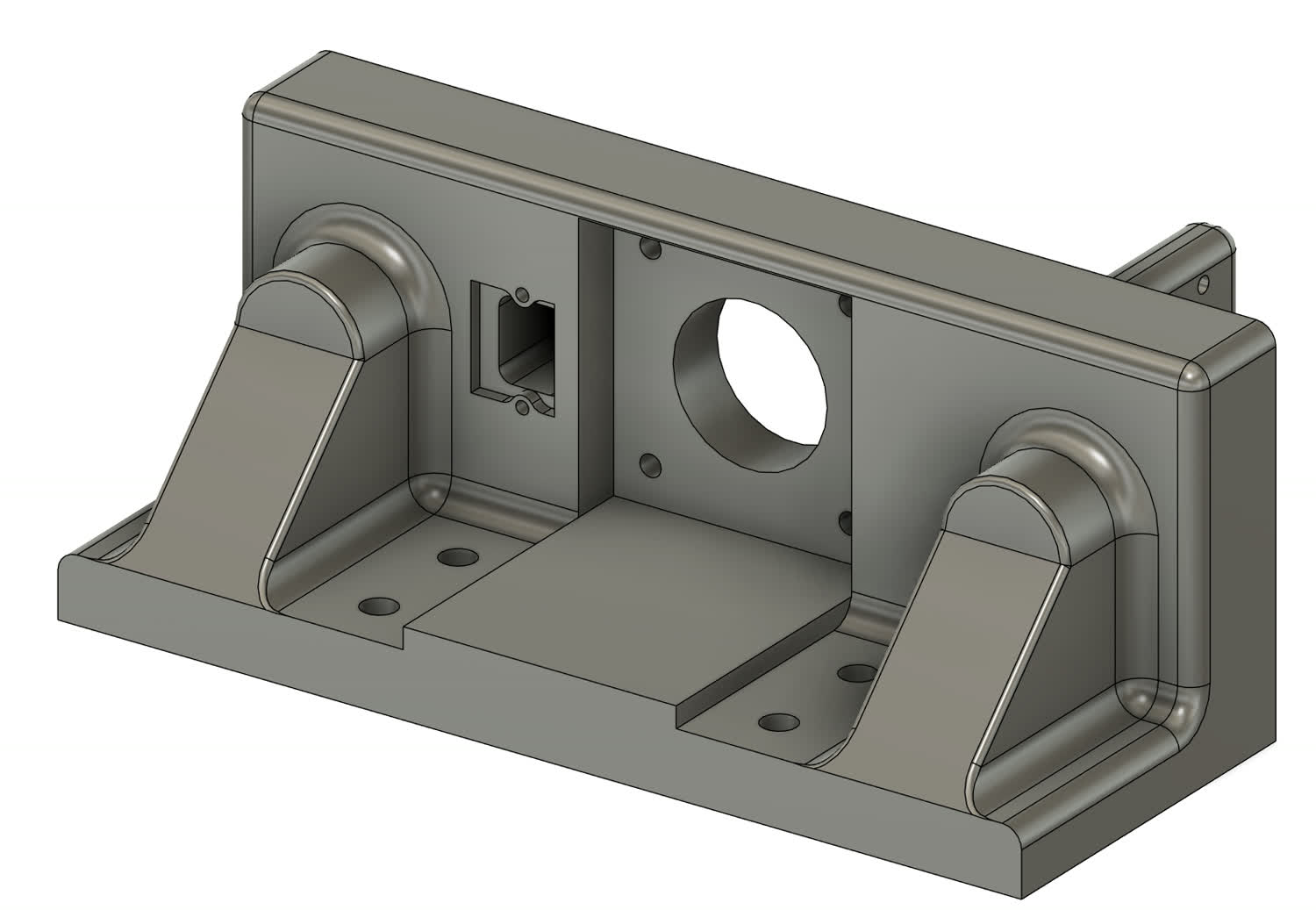
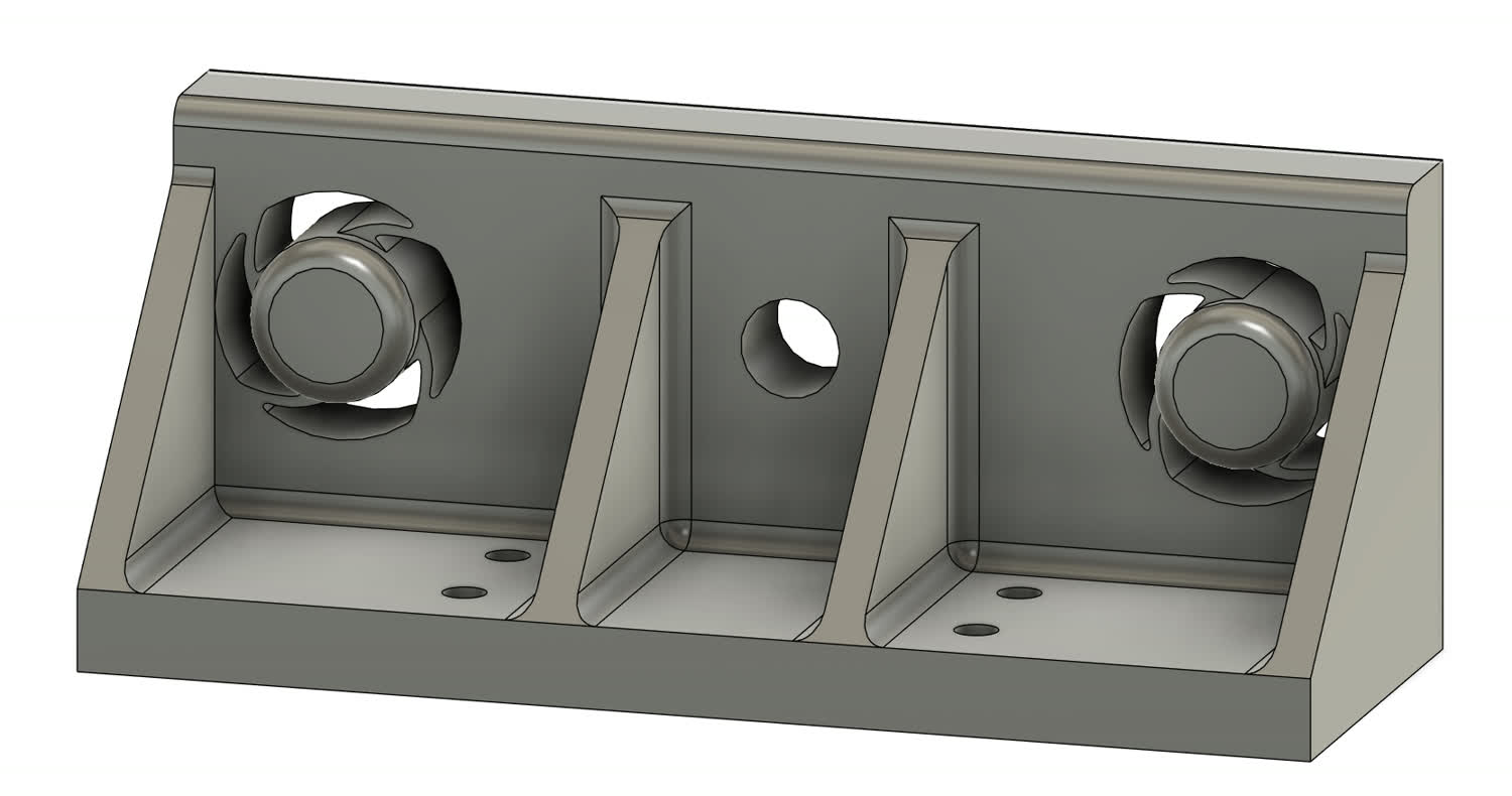
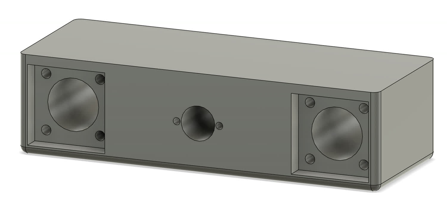
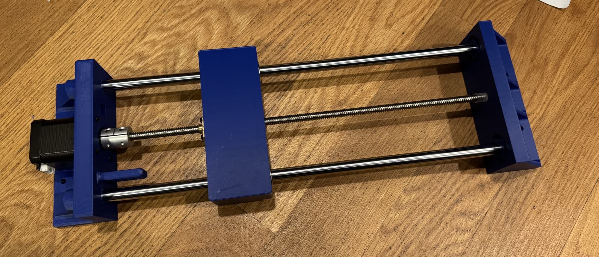
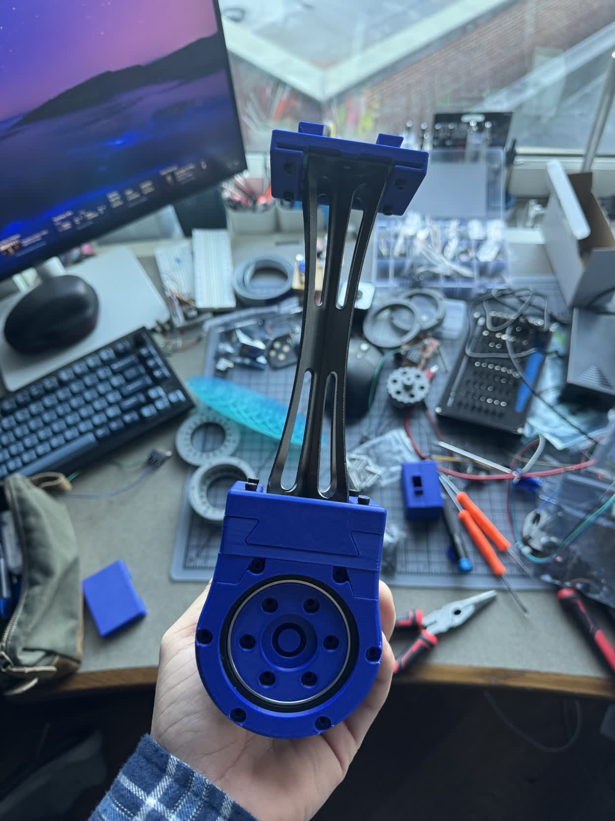
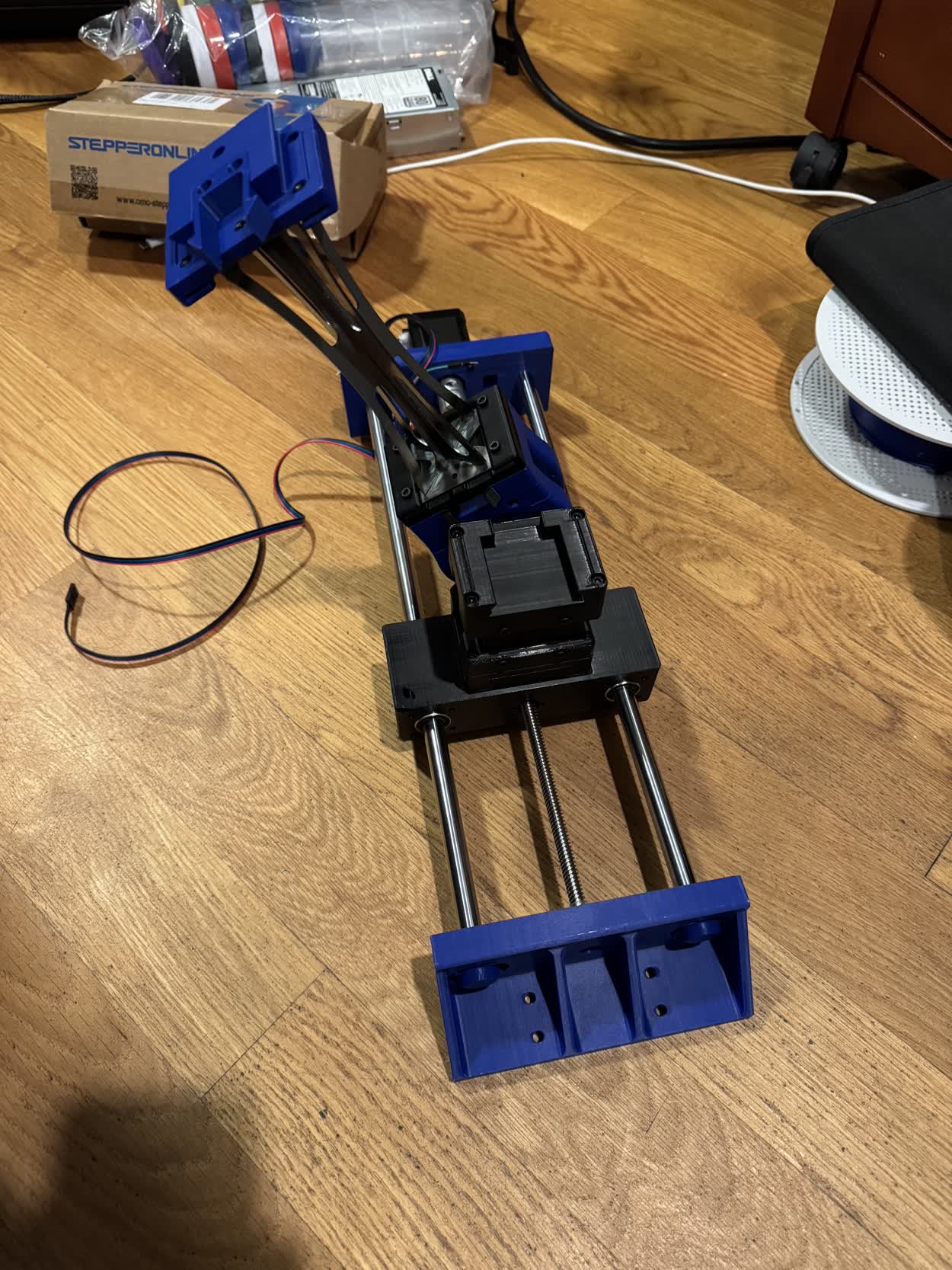
The next part of the project that I wanted to work on was improving the linear actuator model. For this I just hopped in Fusion and based on the dimensions
of the last version designed a new one that would be more robust. There was nothing special during the modeling process, I used processes or tools that I've
documented before. It is still not the finalized model as I have to finish the PCB so I know the size and constraints so I can design a mounting system but
all of the components should be there. I'm again designing around the components that I salvaged from an old 3D printer I had.
Part of the project will be controlling the system so I made my first pass at an IK solver using the FABRIK algorithm. Here is the video that I watched that first introduced me to the algorithm, its
by an awesome youtuber named Sebastian Lague, "I Spent a Week Making a Game about Vaccuming." I coded the solver myself but then
used Gemini to create the visualizer and answer questions. Here is a link to that conversation.
Week 12 Progress:
There was some major progress this week. I got the daisy chain communication working between different boards and also made a simple controller so I could control the steppers with my laptop. The work for all of that can be
found on the pages for weeks 11 and 12.
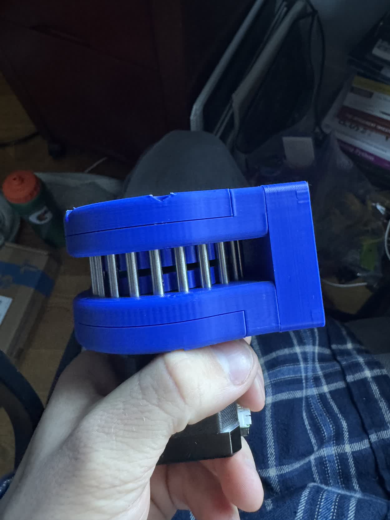
I also solved the stalling issue that I was having with my stepper motors. It turns out that I was trying to step too quickly and take too big of a step. The standard step size on a stepper motor is 1.8 degrees, by microstepping
at 1/8 steps, I shrunk the size to 0.225 degrees. This means that the rotor needs to rotate a much smaller amount and it will have a much easier time doing that and thus won't stall nearly as easily. In this video, I'm squeezing
pretty hard, and I'm having a hard time holding onto the motor itself and I can't get it to stall. I was able to with friends but it now generates far more than enough torque for the purposes that I need.
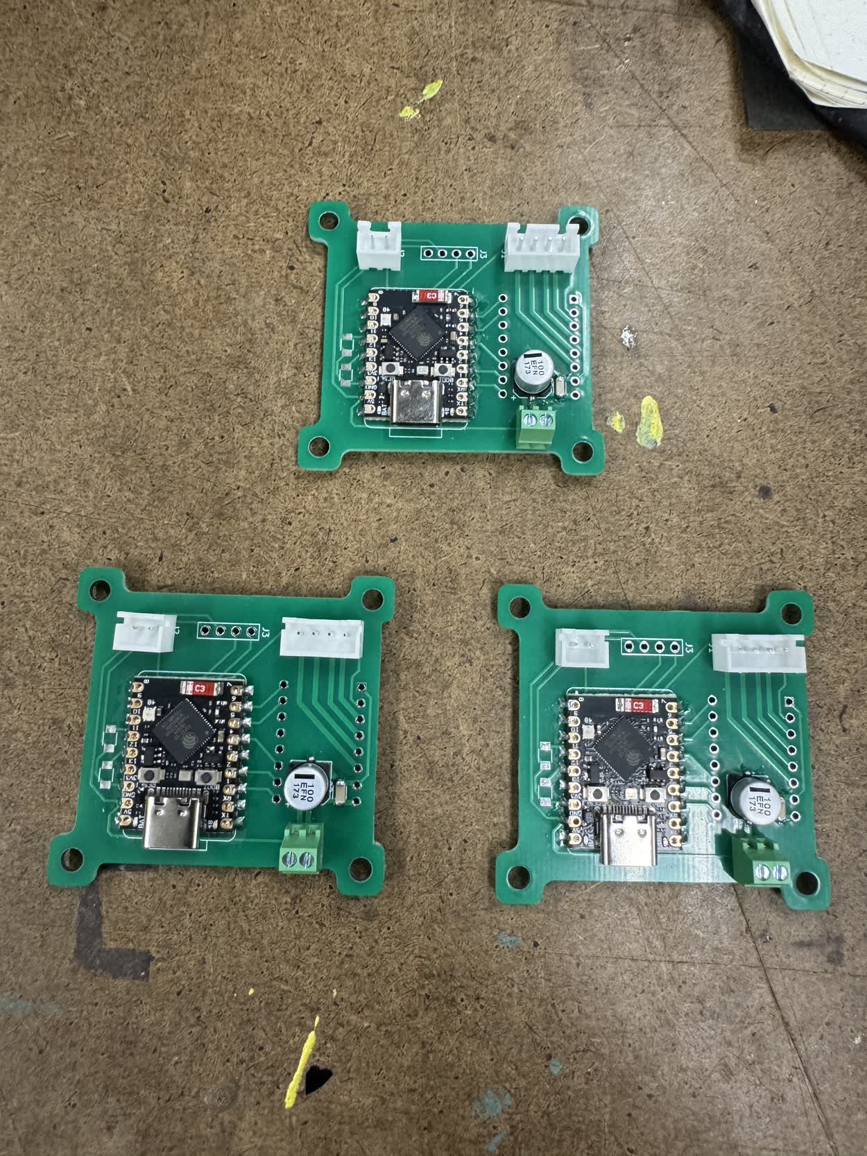
I also spent a bunch of time working on a PCB to work with the DRV8428 which I finally got working!
I also got the limit switch working which was pretty straight forward. I just connected the com pin to ground and then the NC (Normally Closed) pin to a GPIO and set it to be an INPUT_PULLUP. I'll use this for homing for each of the
actuators.
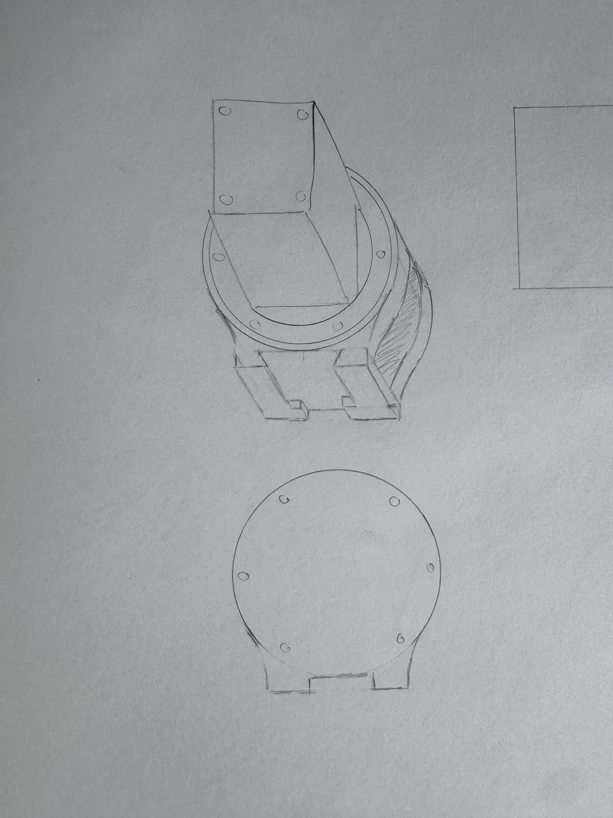
The final major thing that I did this week was started prototyping the connection system. It would be pretty easy to use fastners to just connect the actuators to the connection system but that feels like cheating. I feel like if it is to be a truly
modular and easy to play with system, I don't want to have to use any tools to put it together. I came up with a locking dovetail mechanism that uses flexures to create a buckle on the back to lock it in place. I'm really pleased with the result.
There is definitly some tweaking to do to ensure reliability and strength, I also need to refine the tolerances but as a first design its great!
The Mad Dash to the End!
There was still a ton I had to complete before final presentations. During wildcard week, I had created the members that would bridge the gap between the different
actuators in the system and I also had already designed the buckled dovetail so the last step for that aspect of the project was to modify the buckling dovetail so
that it could mount directly to the steel member.
Fortunatley, it wasn't too difficult of a process, I was able to keep the clip the same and most of the dovetail, especially as I had made it parametric to begin with.
The main thing that I needed to change was the flat face into something that could mate with the steel member.
Coming soon, pictures of the refined dovetail CAD
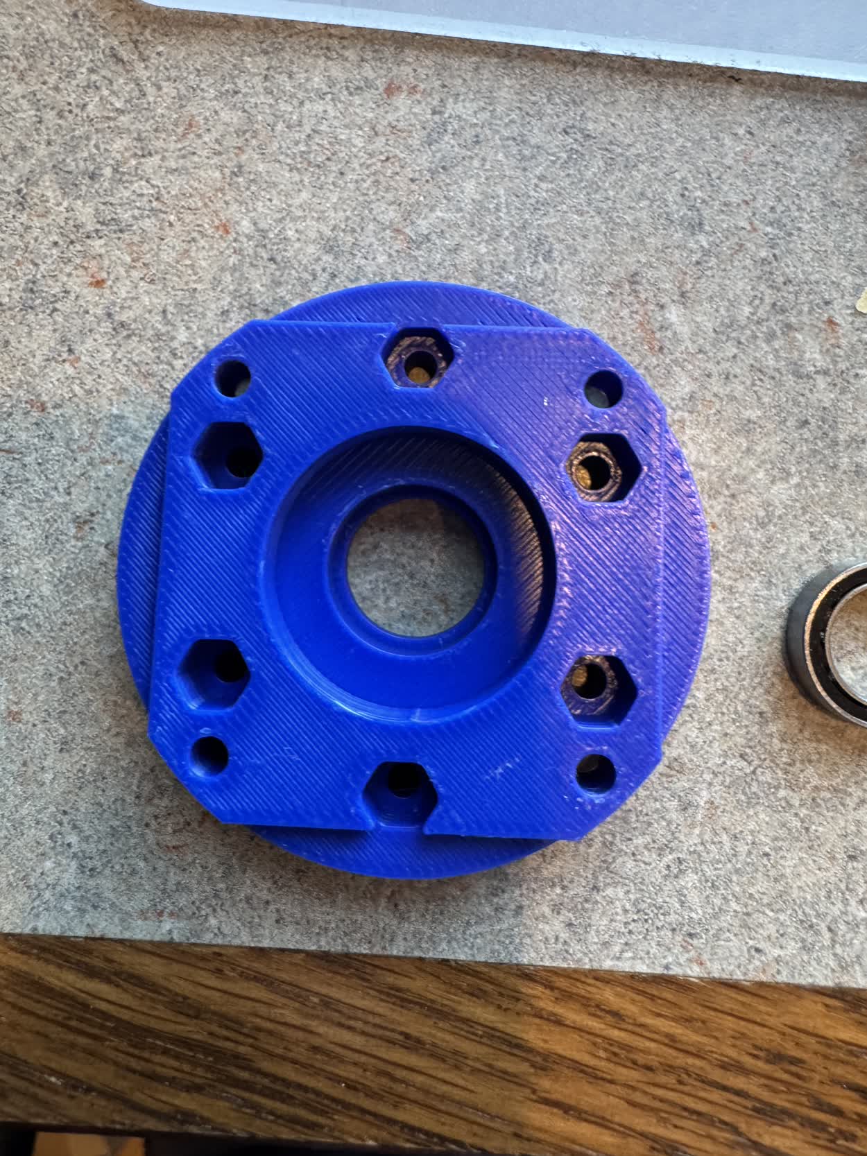
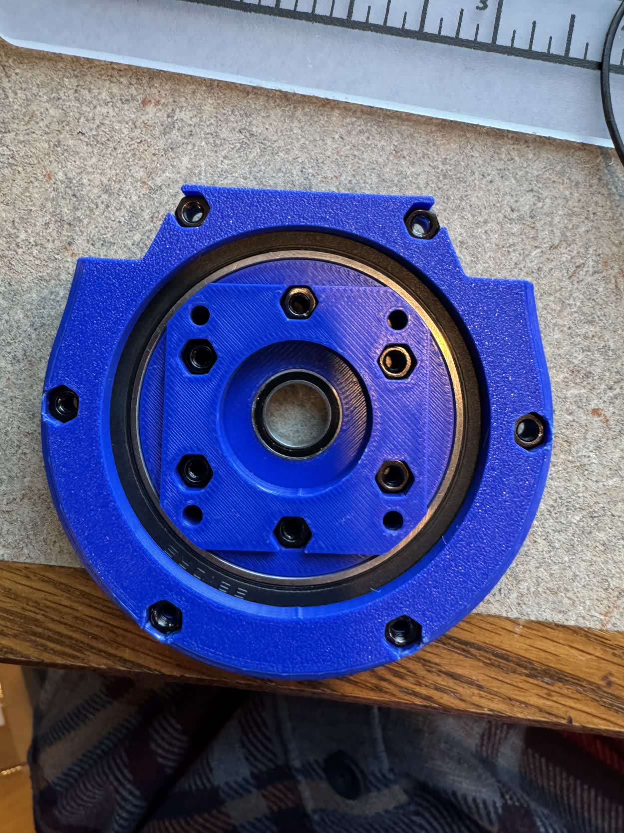
With the member completed, I then needed to figure out how I wanted to mount the member to the actuators. To do this, I needed to add the already existing female
dovetail design to the actuator. I wanted to keep the female dovetail as a seperate part so I could print it in the direction that would be the strongest and also
keep it as modular as possible so I could change things more easily. This was the general design that I came up with.
Coming soon, pictures of the refined actuators
With the design done, I went ahead and began printing and then moved on to assembly.
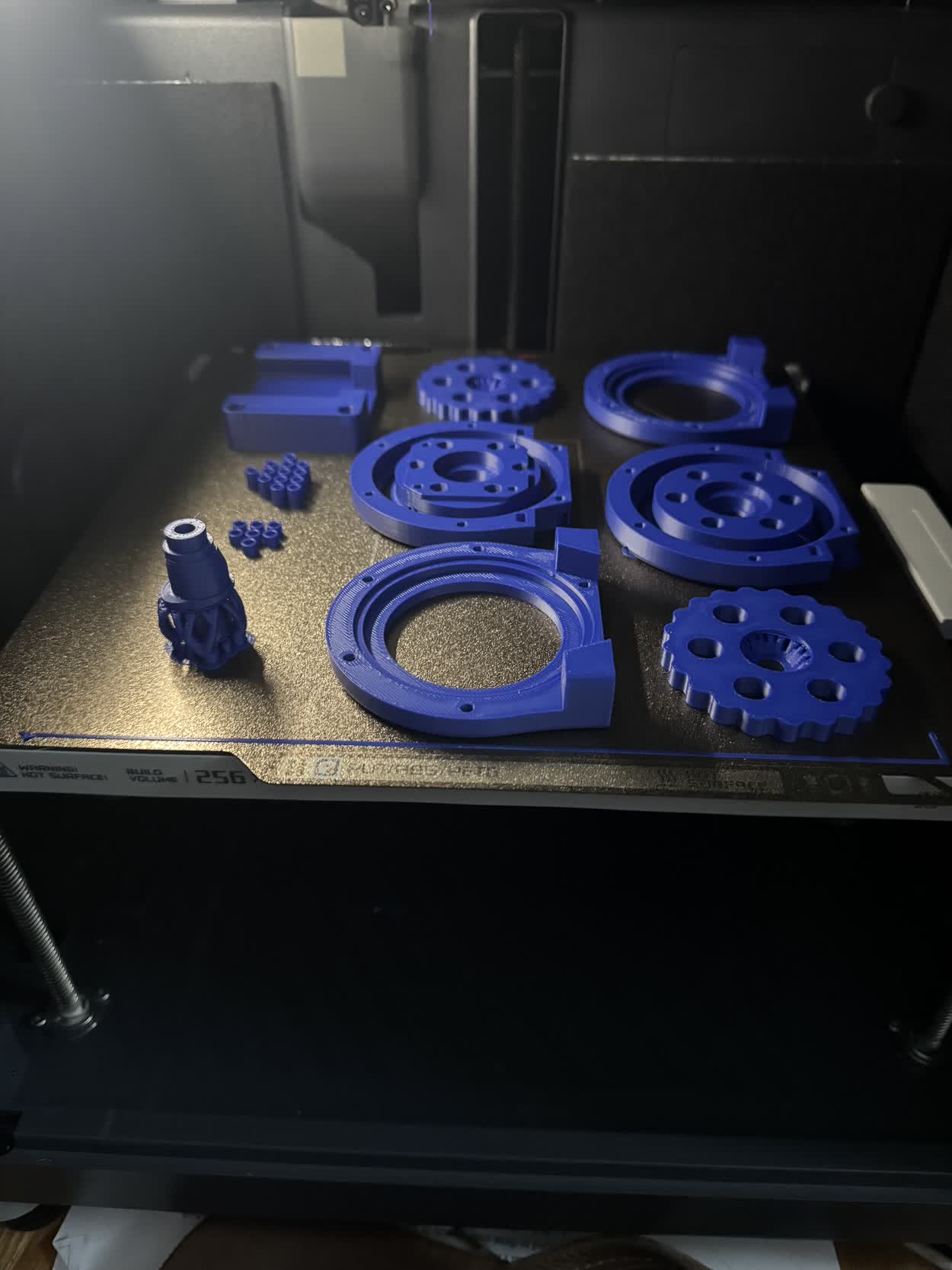
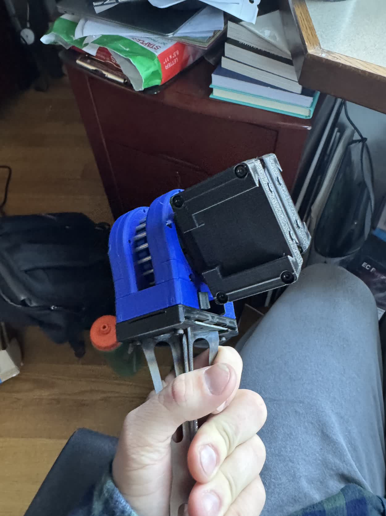
IT WORKED! As you can see in the video, I was super excited about that, it was actually starting to come together! The next part of the assembly
that I had to design was the motor mount, this would enable the conneciton of the next actuator in the system. Again, because of the way that I designed
the dovetail, and how modular it was, I simply needed to design a face that I could bolt it too. The hardest part was tryign to figure out a secure way to
mount the bracket ot the stepper motor itself.
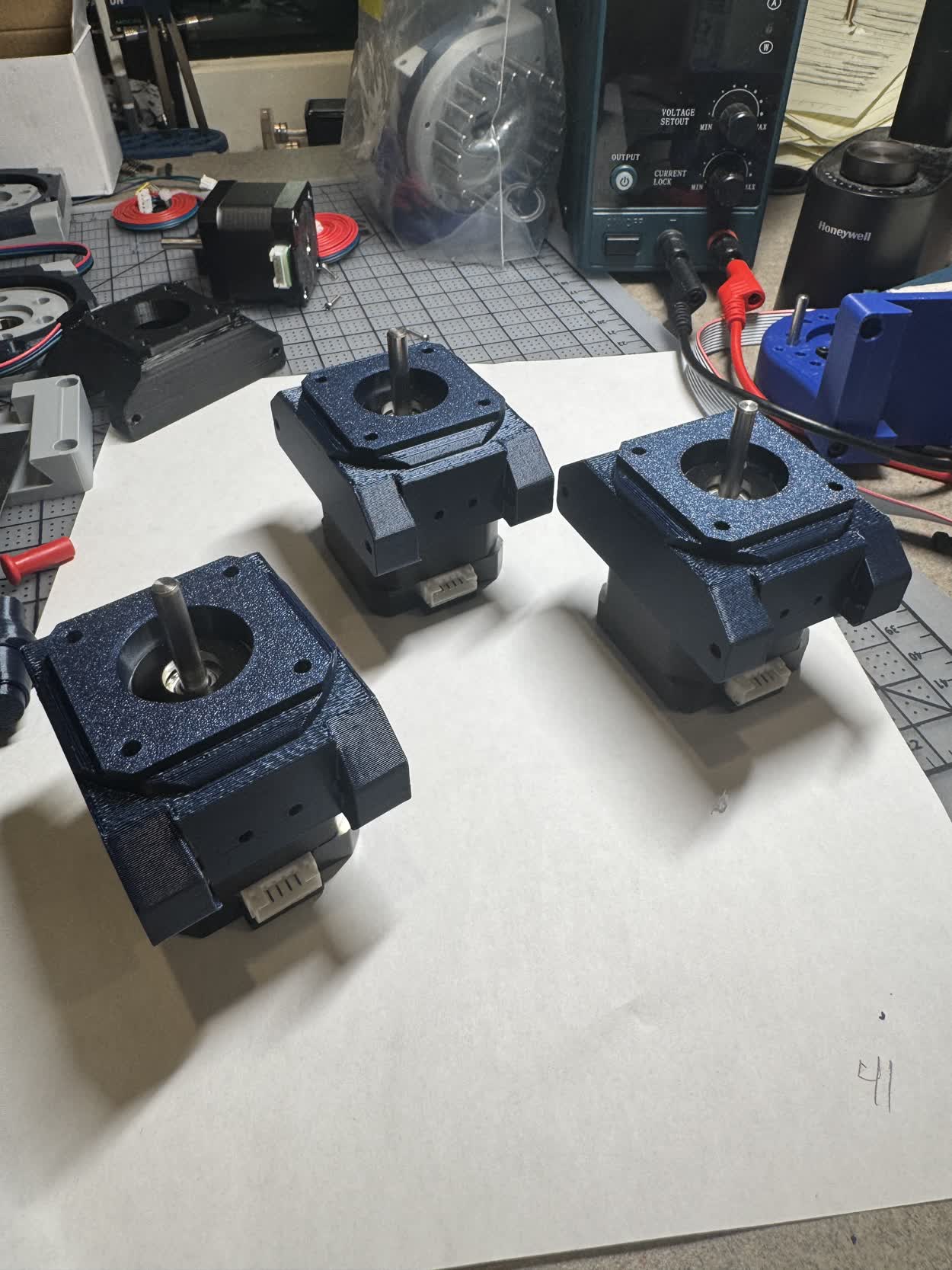
After playing around with a stepper, it turns out that you can unscrew the bolts that hold a stepper motor together from the back and then use
those (or longer ones) to clamp it all back together. You can also use the mounting holes on the front of the stepper which enables mounting from both sides
of the motor. With that, I knew how I wanted to mount the motor brackets and so I was able to jump into Fusion and design them.
Coming soon, pictures of the motor mount brackets
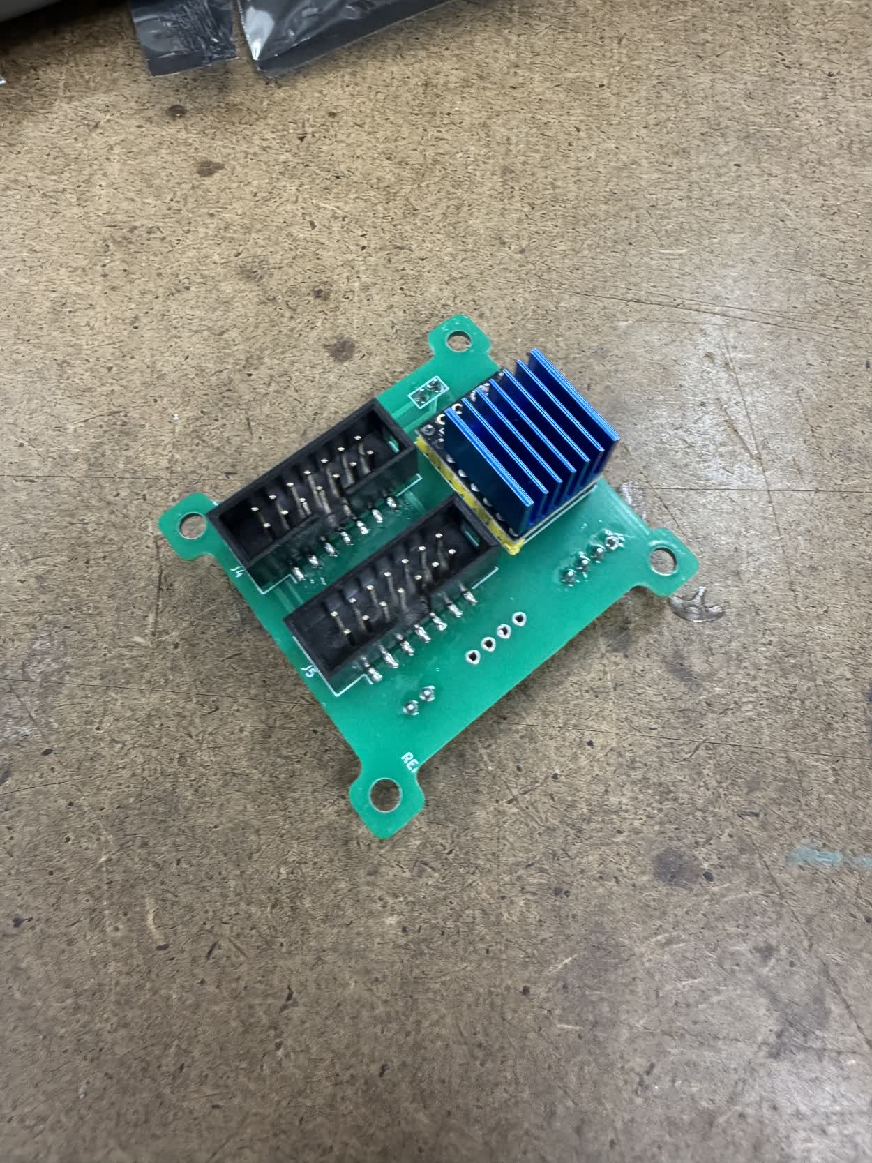
Coming soon, pictures about the board shop PCBs
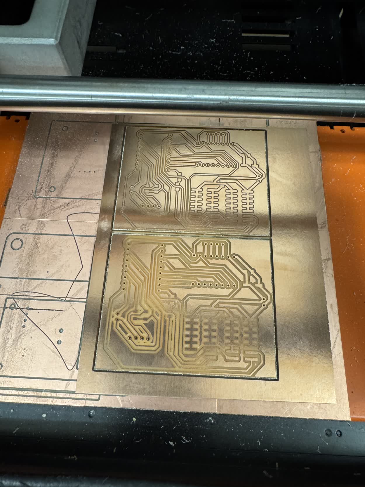
While I was waiting for those to arrive I got sidetracked and tried to start milling my own on the SRM-20 because I wanted to try and start working with the IDC
connectors and ribbon cable. In hind sight, this was a giant waste of time. I should have just been patient and waited for them to come and work on other, more
pressing parts of my project. Regardless, I got carried away and made a version of one of the control boards that could be milled.
Coming soon, PCBS and their schematics
In order to use the IDC connector, I also needed to create a main control module. This would simply read the serial data that was coming in through the USB-C port
and send it out through the GPIO pins. All of the other nodes listen to and send from GPIOs. I could have gotten away with not needing an extra control module but then
everytime I switched the order of the nodes, I would need to reflash the node connected to my laptop to tell it to listen to the USB-C port as opposed to the GPIO pins.
Reflashing code went against the easy of use and simple assembly principle so I decided on an additional control module. This was a really simple circuit though. It was
literally just a microcontroller, a barrel jack for supplying the motor power, and a female IDC connector. I also included a JST connector for an I2C OLED display like used
in one of the earlier weeks in case I wanted to include that in the control module.
Coming soon, a picture of the control module, schematic and PCB
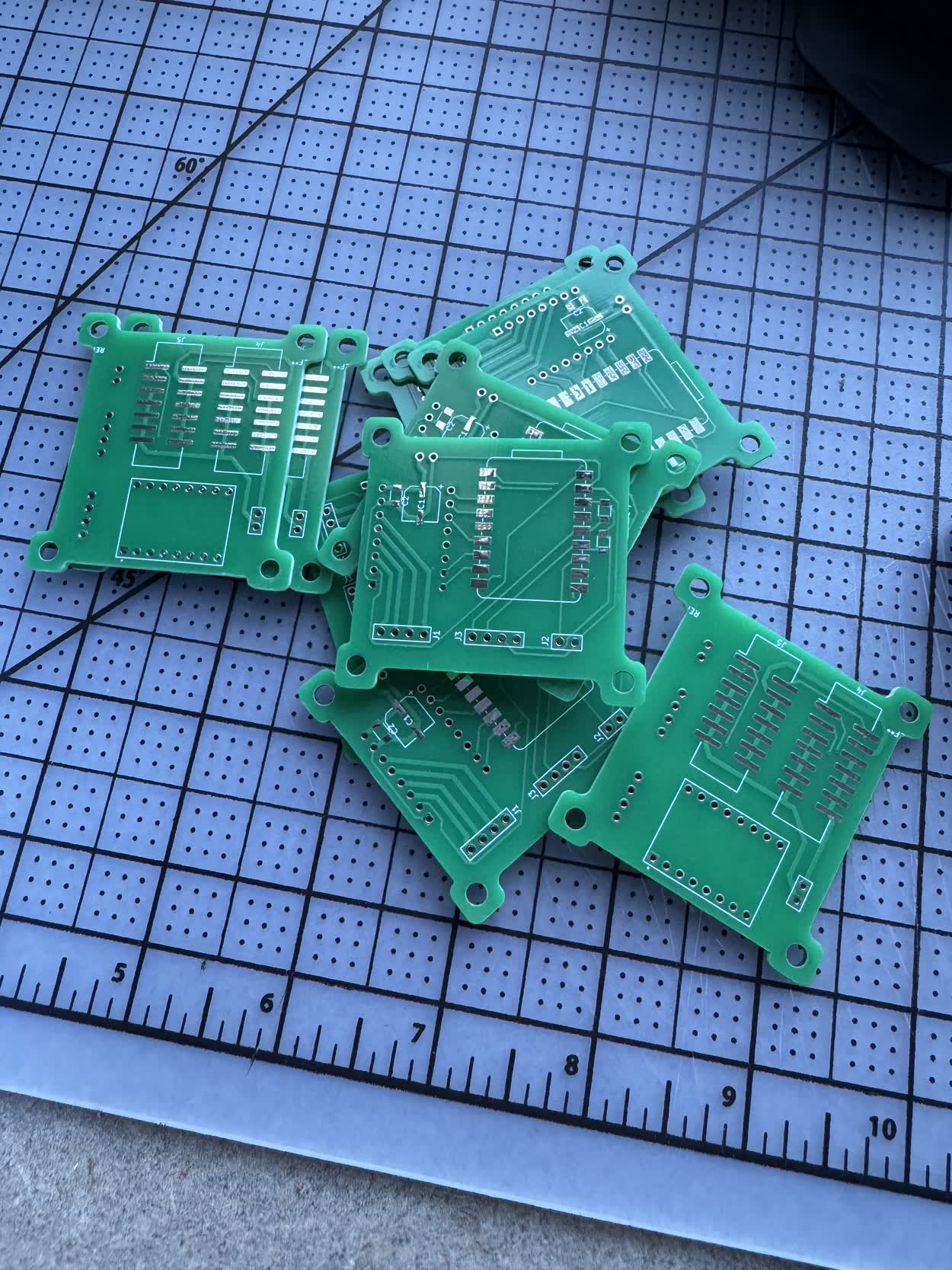
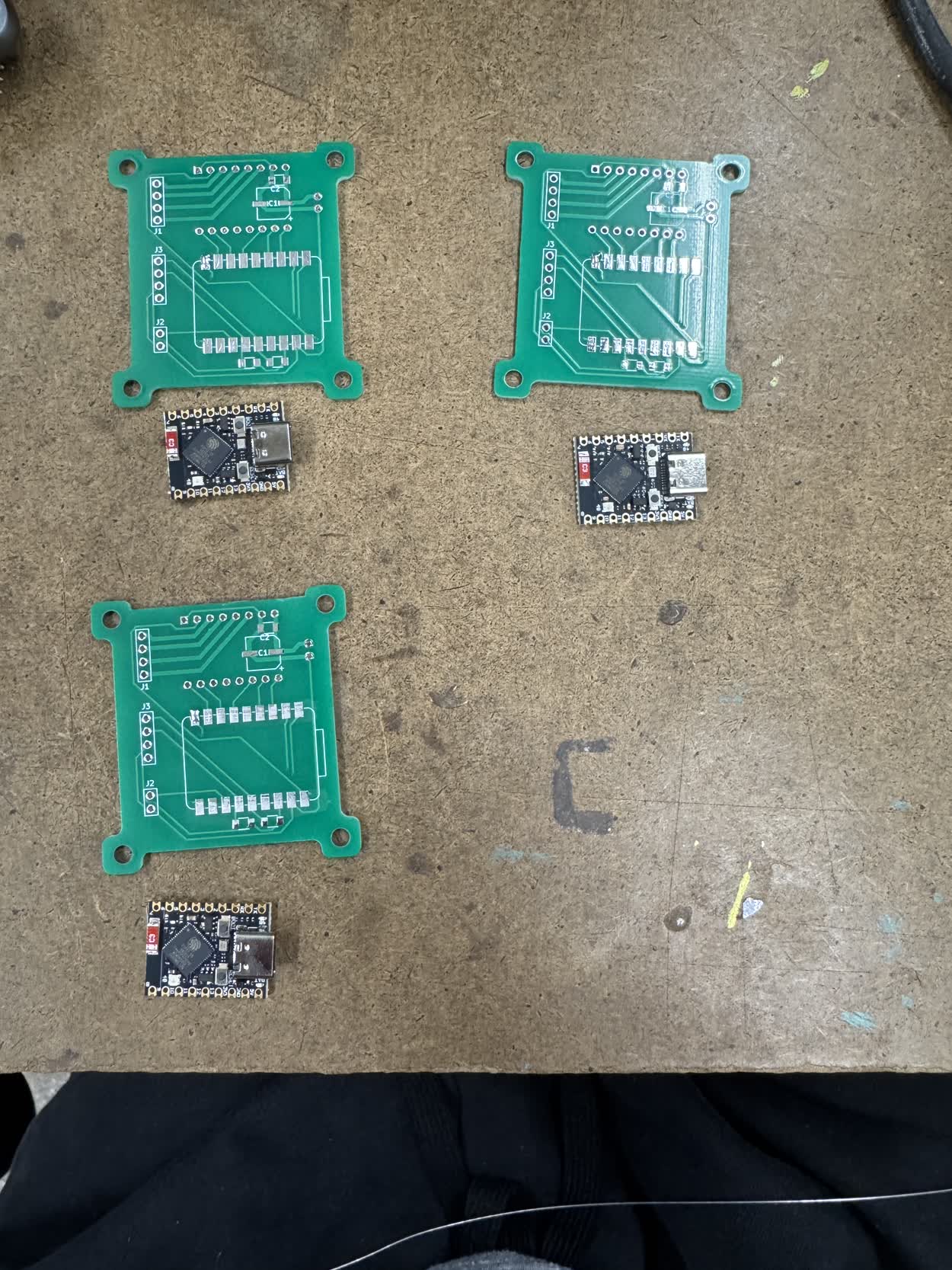
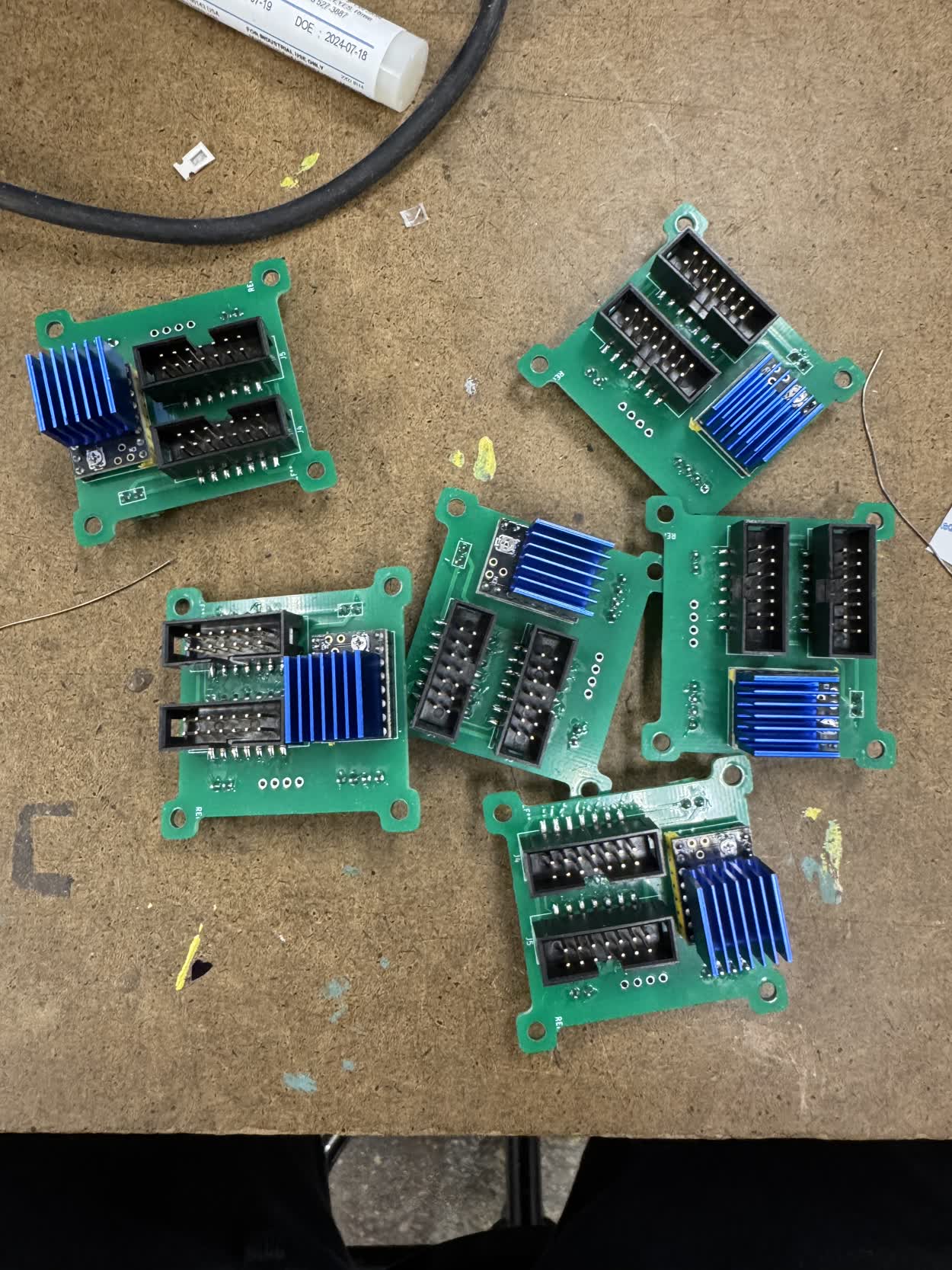
While working on those PCBs and assembling my actuators, the actual boards I ordered arrived! I then went to arcshops to begin assembling them. I decided that I
wanted to try and make five rotational actuators and one linear actuator so I would need to make six of the control modules...
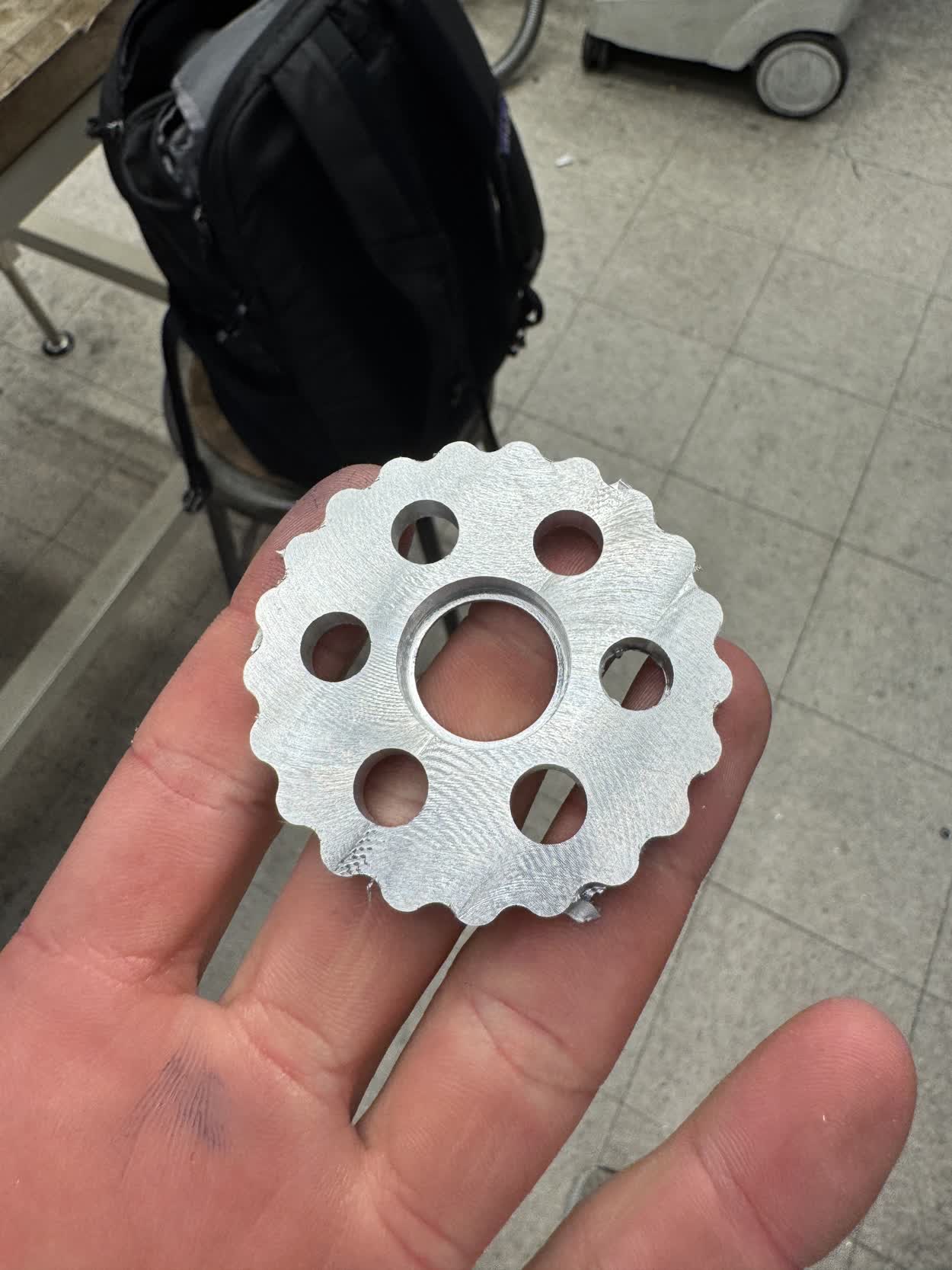
In the midst of all of this, I once again got sidetracked, this time by 2.5D CNC machining. I thought it would be really fun to CNC mill the cycloids for my
drivers. Long story short, I didn't have time. Long story long, I met with Seth and we went over how to create CAM programs in Fusion. We went through how to
use FSWizard to determine speeds and feed for different endmills. We also discussed a few different profiles that could be used and how to set them up for
for different machining styles using the same tooling like HSM (High Speed Machining) or Slotting.
Here is a timelapse of the machining process.
Here is a picture of the final piece. The dimensions were off by a surprising amount, up to around 14 thousandths of an inch. I talked to Seth about it at length
and we couldn't determine the problem. I think it was the Friday before final presentations when I was discussing all of this with Seth and determined that I did
not in fact have time to machine ten of these, especially if I could not figure out why the machined part was so out of tolerance.
INSERT PICTURES OF THE MODELS FOR THE DIFFERENT MOUNTING BRACKETS
With those all completed, I had everything I needed for the project done. It was now time to start working on improving my GUI. I figured I would work with Gemini
on this one as I didn't have a ton of time left and to create a GUI that was somewhat aesthetic and had all of the functionality I wanted. Here is a link to the
conversations that I had with Gemini:
Here is a video using my main control board and the onboard actuators that demostrates some of the features, this was taken before all of the features described had been implemented. This also happened to be the last video I took before I ran into catastrophic failure.
Catastrophic Failure
Everything was working when I went to bed the night before final presentations and I was polishing up the GUI when the main controller stopped working. I was testing the individual nodes, and as I unplugged the fourth node that I had tested and plugged in the fifth, my computer no longer registered the main controller. I have no idea what happened. I changed nothing between that test and the others that I had performed. As soon as I realized something went wrong, it was about 10 in the morning at this point and presentations started at 1:30, I started freaking out.I immediatley started gathering everything that I thought I would need, I had bigger plans for my presentation but I immediatley jumped into recovery mode. I went to the Media Lab and found Quentin. We started looking over my boards and couldn't visualy identify any problems. We found a short between 3V3 and ground which could definitly contribute to the problem but I don't understand why it would have been working before and then randomly stop working. We then tried to bypass the control module itself and plug straight into one of the IDC In ports on one of the actuator control modules which proceded to fry. The linear voltage regulator got super hot and almost burnt my finger. We double checked pins, outputs, looked for shorts and could not find the problem, trying on each controller and proceeded to fry.
We found two that were working and I set up a demo to do with them and when I was homing them, it spun the wrong direction and one of the wires was going to get tangled, in a panic I unplugged the IDC connector as opposed to just turning off the powersupply. Noteably, neither of those controller worked again. I'm beginning to suspect that the issue comes with a disturbance in teh communication that upsets the MCU and fries it.
Quentin eventually just told me that in the future I should avoid ESPs because of their reliablitily problems and should switch to RP2040s which I will likely do when I continue the project.
There I was though, having had everything working perfectly the morning of final presentations and by the time they had begun nothing could move. Words can't really begin to describe how dissapointed I was. I had poured so much time and effort into the project, brought my idea to life and had it completley working only to lose it hours before the presentation I had been looking forward to the whole time. I still had a great project to show and it went well, but I was deeply unsatisfied and resented it. I was able to fake some amount of motion by simply plugging a MCU into my laptop and wiring up a TMC2209 on a breadboard and running a simple stepper loop to rotate the base but I lost all complex functionality.
Resolution
Regardless of how the presentation went, the compliments from classmates and staff, I felt incredibly unsatisifed and found myself unmotivated to do anything the next day. I had finals to study for and documentation to write but I couldn't even bring myself to begin. After some reflection, I realized that I wouldn't really be able to let it go and move on until I proved to myself that it was all worth it and actually worked. I thought about it some more and realized that because of the way that I had progressed through the project, spiral development, I could return to the last closed spiral and work from there. Fortunatley, before I had any of my onboard controllers, I had tested and gotten everything to work on breadboards. Therefore I could jump back to breadboards to at least demonstrate most of the lost functionality. I had to sacrifice the homing as I couldn't plug the limit switches into the breadboards as they were mounted to the actuators and I didn't have cables long enough but I could use the set zero feature that I had added to simulate them. I refered to my work from week 11 to get the breadboards back up and communicating and I was able to bring the system back to life. While the wiring wasn't as clean as I was hoping and it was a day too late, I was able to see the final project come together.Final Presentation Notes
In order to avoid any confusion, I want to go ahead and answer all of the questions on the final project page, explicitly, even if I have already done so on this page.
What does it do?
What I ended up designing and building was a modular robotics system, almost like lego, that provides you with easy to use, snap fit components and enables you to build much more complex systems out of identical
components. It currently is able to move between saved positions, real time speed adjusment, homing. The system works for an arbitrary number of nodes as when the control program is run from your laptop, it runs
an auto-addressing function that gives nodes temporary addresses based on positions in the chain. There are a few other smaller details that I discussed above but these are the most relevant details. As for actual
purpose, it does not explicitly have one. It would have nice to turn it into a pen plotter or a camera arm but I ran into some technical difficulities. None the less, based on the connection system I designed and
the daisy chained communication, it would be incredibly simple for you to add your own end effector to the system to create customized functionality.
Who's done what beforehand?
There were some interesting class projects that seemed related to my project which I definitly read through and explored, particularly Miana's 5DoF voxel assembly robot and Chi-Li's modular robotic system.
I'm sure there are companies working on this type of technology as I think has lots of potentail for application but I did not research into them as I wanted to see what I could come up with. It would
be fun to now go back and look with a first iteration under my belt and see what inspiration I can find.
What Sources did I use?
Throughout the entire website, I tried to link all the different sources that I used. They ranged from youtube videos on inverse kinematic control algorithms to CAD techniques. I also linked to many conversations that
I've had with Gemini and or ChatGPT, both of which greatly increased the scope of project that I was able to take on. I read through various data sheets on different components and microcontrollers, perhaps the most
notable one was the DRV8428, that driver gave me quite a hard time.
What did I design?
Every mechanical component in the entire system was completley designed from scratch. Obviously I bought off the shelf hardware but the drivers, the steel members, the buckled dovetail... all of it is entirly
custom. I also designed various PCBs that I either milled or sent out to a board house to get machined.
What materials and components were used?
In the final project, I ended up using Nema 17s, TMC2209 Drivers, ESP32S3 Super Minis, custom pcbs for both the onboard controllers and main control module, limit switches, IDC and JST connectors,
various M3 hardware and bearings. I also used steel plate for the members and PETG for all of the printed components.
Where did they come from?
Most of if not all of the hardware I bought on Amazon. The steel came from the extra that they had available in the CBA shop which I was fortunate to find enough of. The Xiao ESP32S3s I got from the Arch shops.
How much did they cost?
| Item | Quantity | Price |
|---|---|---|
| 20 Limit Switches | 1 | $8.36 |
| Dark Blue PETG | 1 | $19.99 |
| Grey PETG | 1 | $17.99 |
| 4x20 mm Dowel Pins | 2 | $5.98 |
| 15x21x4 mm Bearings | 1 | $9.29 |
| 50x65x7mm Bearings | 1 | $26.79 |
| M3x30/35/40/45/50 mm Bolts | 2 | $8.99 |
| M3 6-25 mm Bolts | 2 | $9.99 |
| 5x ESP32S3 SuperMini | 3 | $17.99 |
| 3x7x3 mm Bearing | 3 | $8.29 |
| 5x TMC2209 | 1 | $21.99 |
| 5x Nema 17 17HE19-2004S | 1 | $49.99 |
| 10x15x4 mm Bearing | 1 | $9.99 |
|
10x Custom PCB from JLCPCB (Boards - $6.20 | Shipping - $38.09) |
1 | $47.47 |
| 02x07 Female IDC Connector | 20 | $1.05 |
| 02x07 Male IDC Connector | 20 | $1.05 |
| JST Crimper Kit | 1 | $24.99 |
| 14 Strand Ribbon Cable | 1 | $24.99 |
What parts and systems were made?
Besides the hardware, everything in the system was completely custom, I have the files for everything that I will upload to this site at some point soon.
What tools and processes were used?
I used Fusion 360 throughout the entire project, a CAD modeling tool. I also used my Bambu P1S 3D printer which enabled this entire project, without it, I wouldn't have been able to get it done. I also used the XTool metal laser cutter and a TIG welder. A laser cutter and router table for the base plate. A soldering iron and PCB mill, the SRM-20, for all of the electronics. I also used KiCad for desinging all of the PCBs
What questions were answered?
I don't think there were any questions that I had in particular. I was definitley curious just how far could I push myself in a semester to create the coolest project I could and I'm pretty happy with how it turned out. Otherwise, there were definelty some things I was curious and wanted to explore like tolerancing in 3D printing, cycloidal drives, electronics design.
What worked? What didn't?
I think a lot of things worked really well, through iteration, I was able to home in all of my designs to fit really well together. The steel members worked great and so did the cycloidal drives. I think the buckling dovetail and the drivers are what I am most proud of. I ran into a lot of issues with electronics throughout the project, that was definitley the side that I was less comfortable with but I think it's definitley something that I want to work on in the future. Obviously the biggest failure was with my onboard control modules. I have been studying for finals so I have yet to be able to detemine the issue but I will figure it out. I need to know what happened.
How was it evaluated?
If we recall the goals/parts of the project I wanted to complete in Week 8:
- Linear and rotational actuators
- Ligaments between the actuators
- Control of individual actuators
- Control of actuator systems
- Communication between actuators
What are the implications?
While I didn't design the system with a particular use case in mind, I wanted it to be very easy to pick up and work with. I didn't want it to be overly complicated or unintuitive. With that, I wanted to make it super easy to customize to whatever you wanted to use it for which is totally possible because of the dovetail design. By having a flat face oon the back side of either dovetail, it allows you to design any particular end effector you might need for the system, include the electronics and simply plug it into the last node. You'd need to add specific controls for it in the GUI but it should be able to easily detect it if you start with the onboard actuator code.
Future Ideas
- Mold and cast all parts of rotational actuator
- Create a FOC for a DC motor
- Design a closed loop stepper system with FOC
- Claw module