Week 0: Computer Aided Design
Project Idea:
The goal for the week is to design and CAD a "functioning" workbench. When I say "functioning," I mean it as in modeling all of the moving components so that they move together and work as they are expected to. I also want to try and render the whole bench in Fusion's native rendering system.
Features:
- Robotic arm light that can double as normal light
- Magnifying lens
- Helping hands
- Custom part/tool organization/storage
- Caster wheels
- Powerstrip easily accesible
- Drafting arm
- Pivoting table surface for drafting
- Maybe interchangeable table surface
- Clamp/ballvise
- Built in speaker
- Wireless charger for phone
Plan
I haven’t left myself a ton of time, ideally I would like to render it in blender as I don’t have any experience with it. To start, however, I will try and design the whole thing in Fusion 360. I will also be trying to implement actual parts, sourcing them from McMaster Carr where I can.
I have some experience in CAD from past projects and so I wanted to try and push myself to use some of the features in Fusion 360 that I haven't used before.
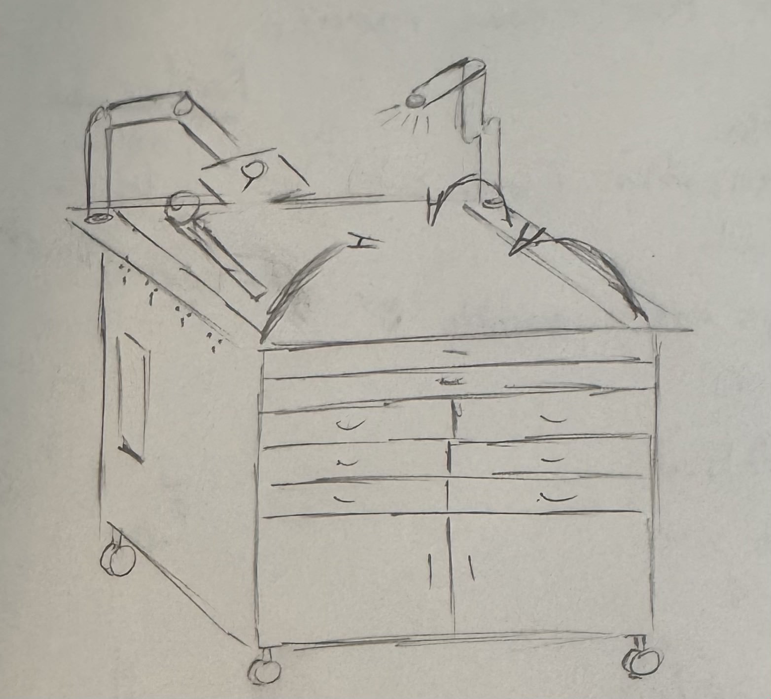
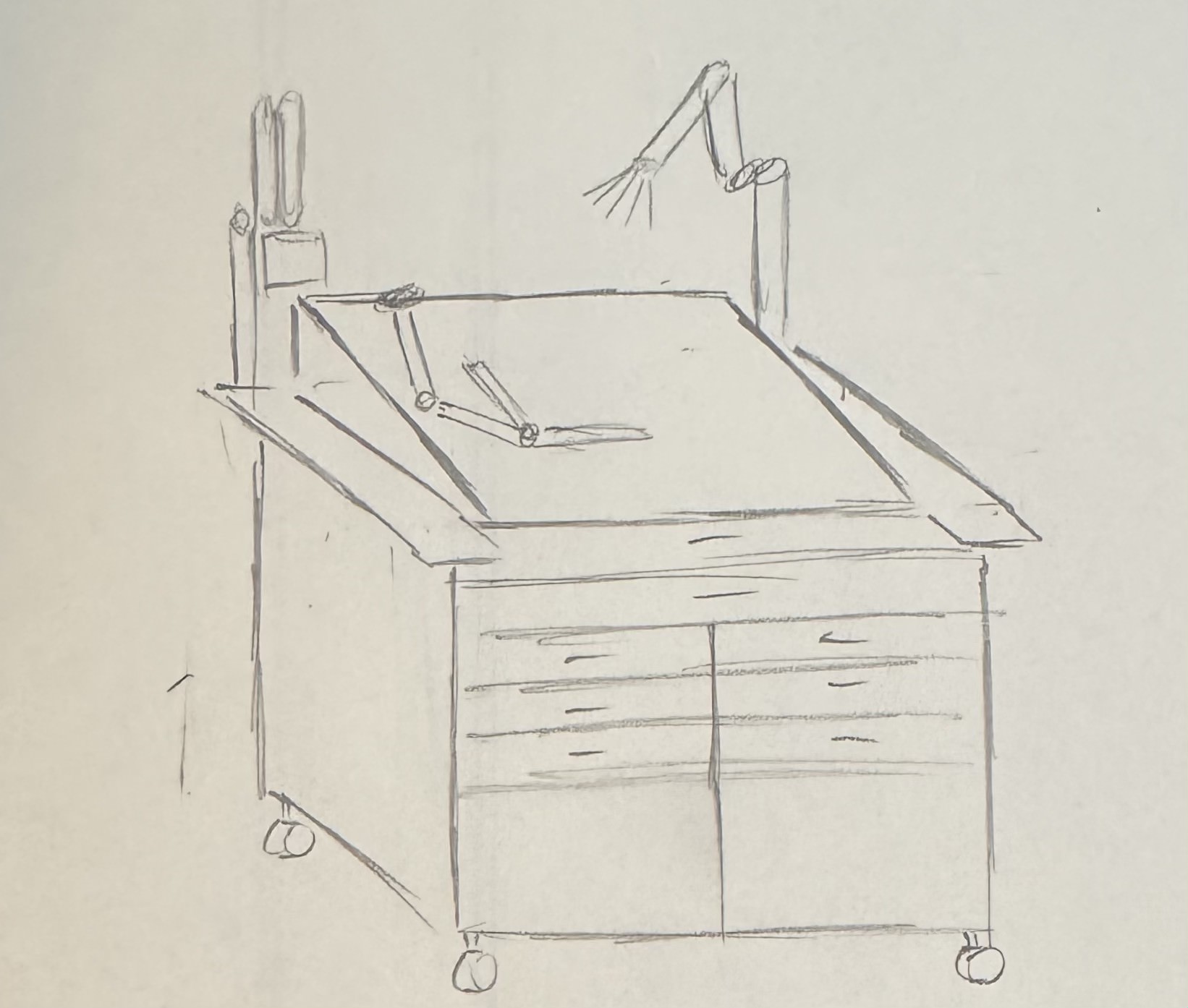
I sketched these in just a few minutes to help myself visualize what it was that I wanted to try and design. I have found I've found that it is a lot easier to CAD when I can see what it is that I am trying to CAD as opposed to just trying to put it from my mind directly into CAD. I also think its a great way to quickly prototype.
Excecution:
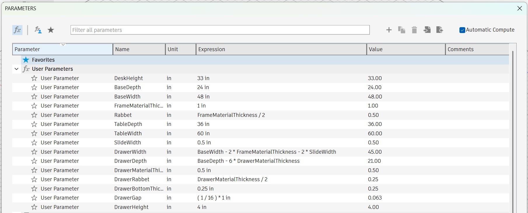
I wanted to try and make the design as parametric as I could. I haven't used this feature of Fusion before and I figured it would be good practice, plus it will be super useful/required for future projects. Here are all of the parameters that I ended up using...
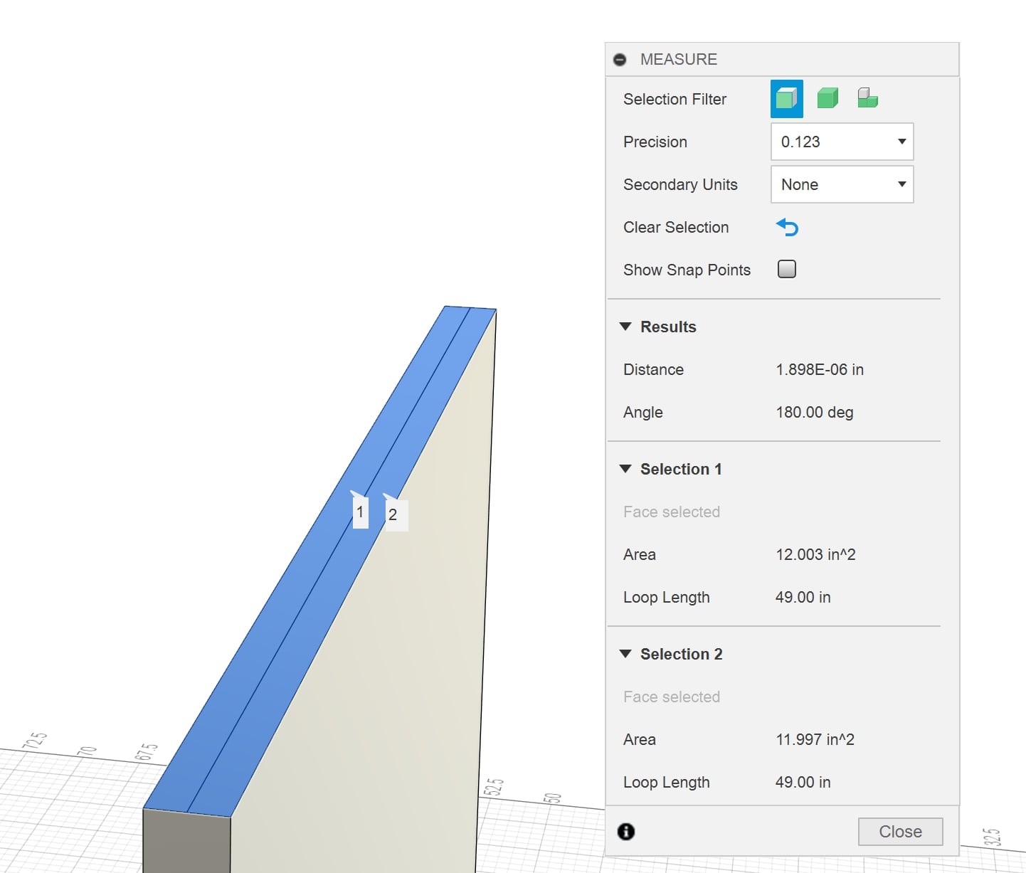
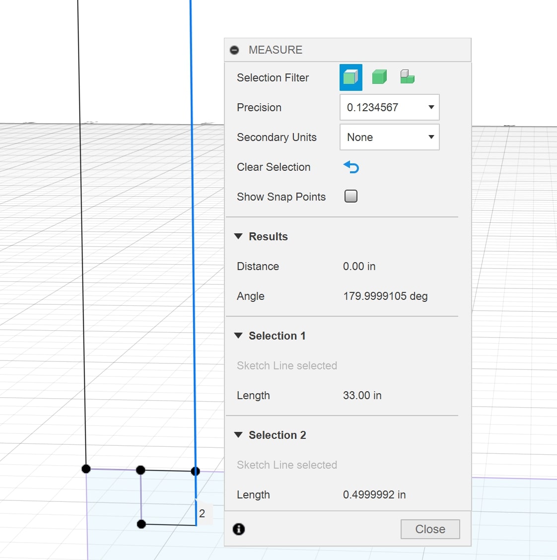
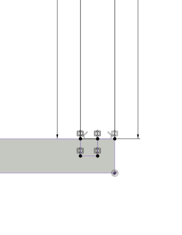
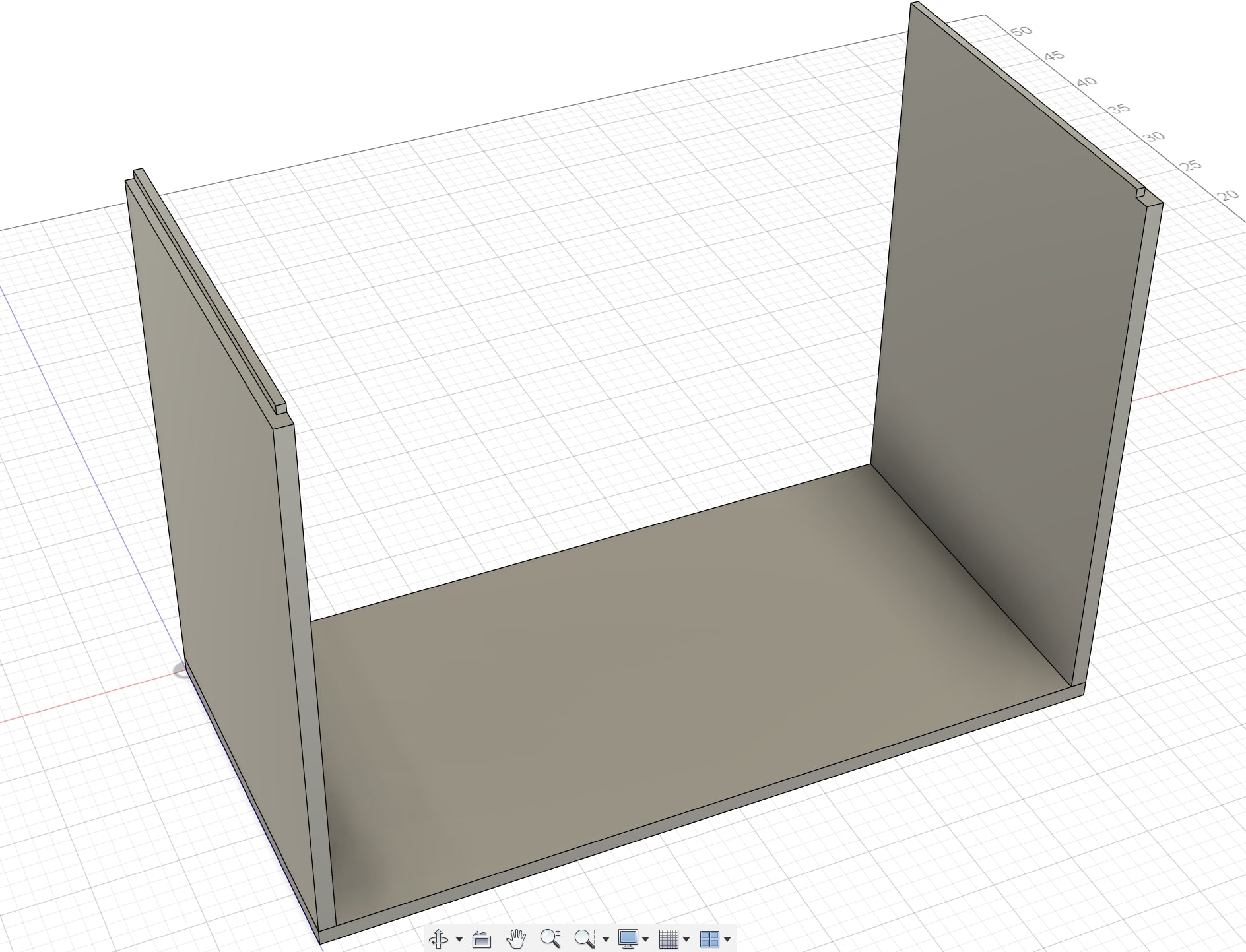
I wanted to start by building the frame of the workbench itself. I started with the base of the frame. I wanted to design it so that
it could actually be assembled which meant including rabbet joints in the pieces as opposed to just flat surfaces on the edges. This
presented a larger challenge than I was originially anticipating. I think there was an artifact in my original sketch that left everything
slightly off from one another and when I projected that surface into the next sketch, it carried over.
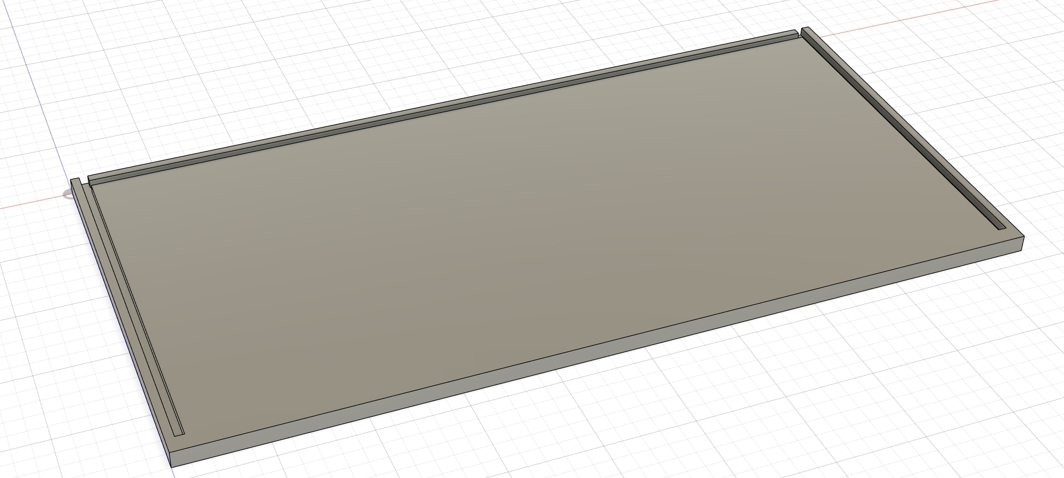
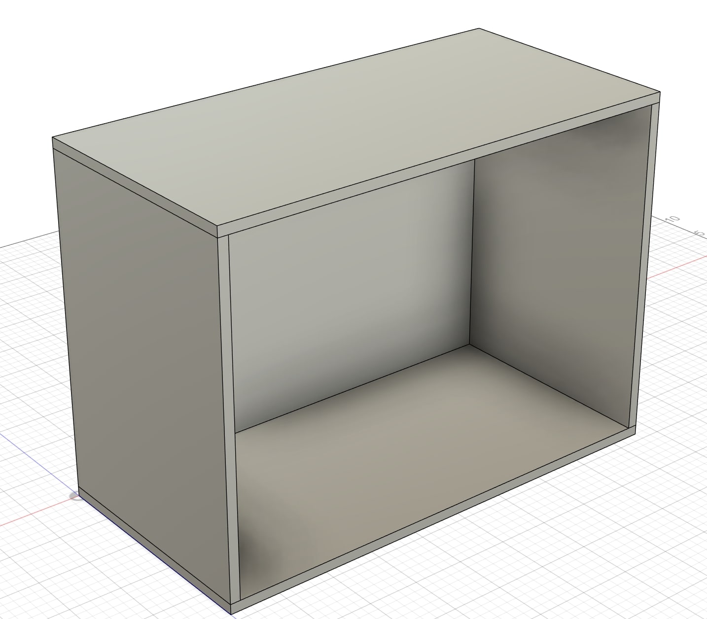
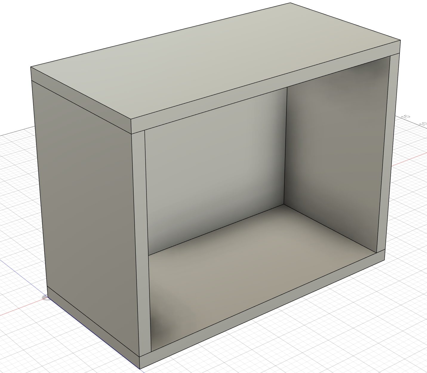
After creating a new file, remaking the parameters, and first sketch I was able to finally make the base of the frame.
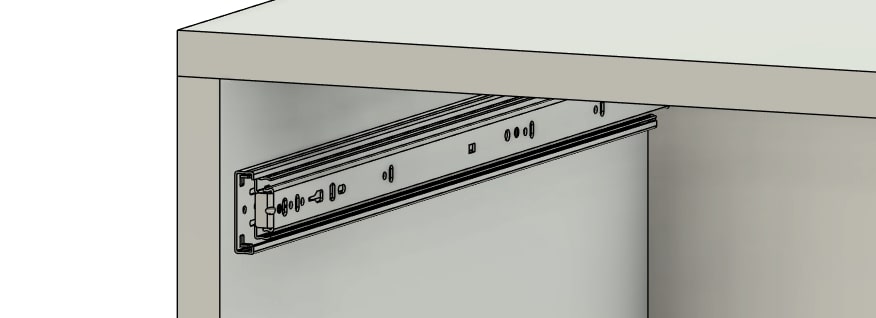
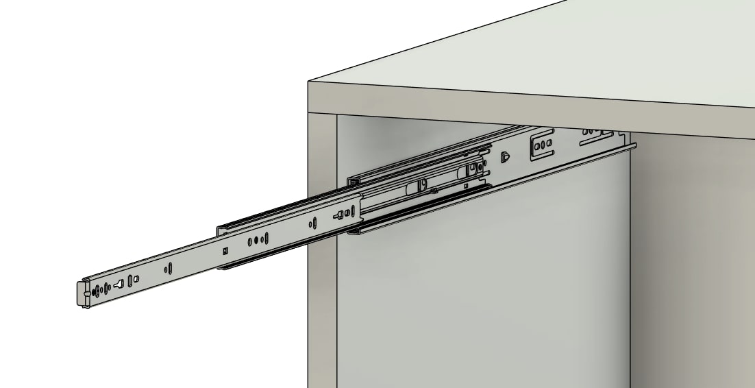
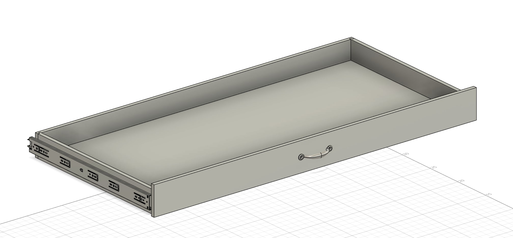
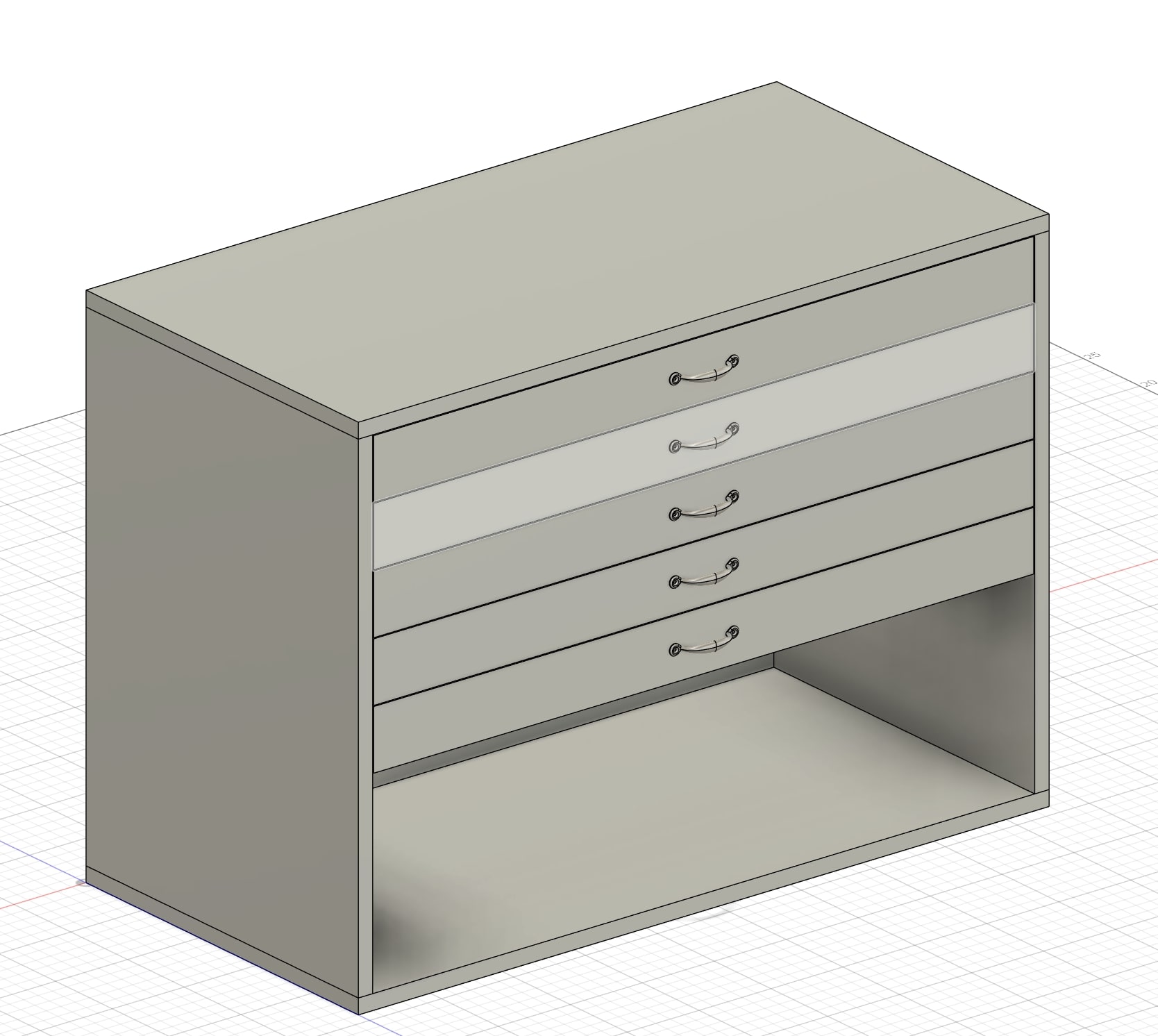
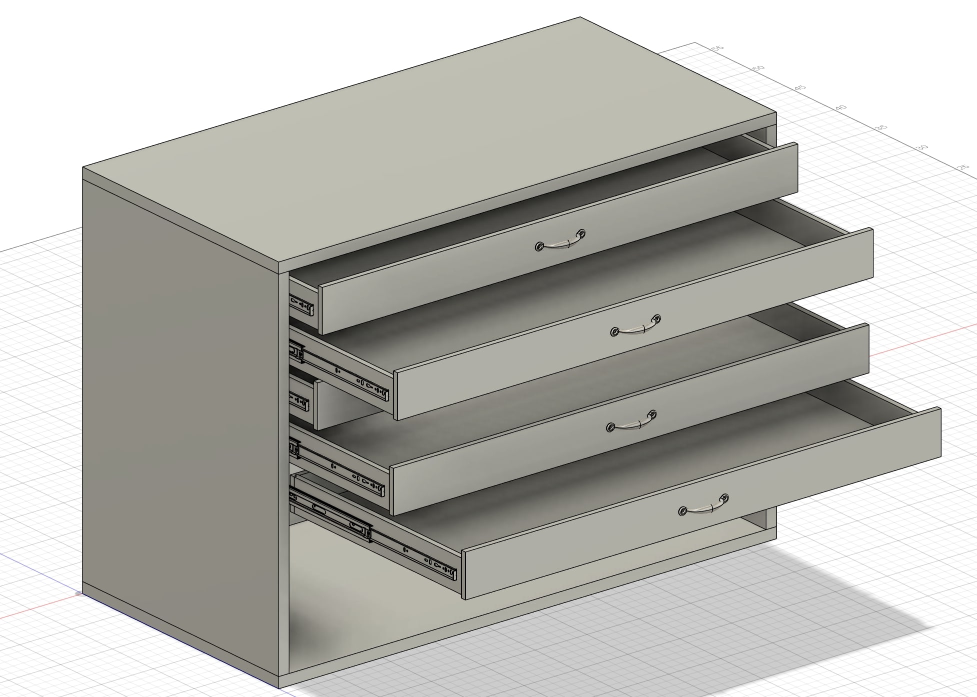
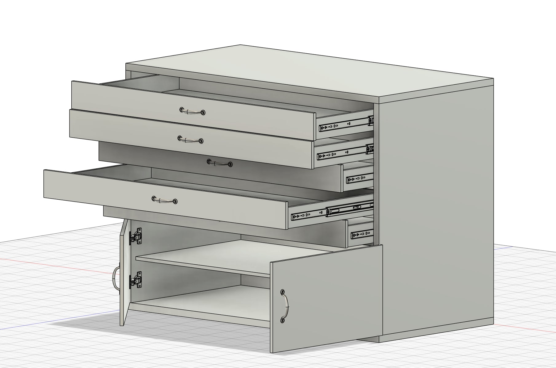
The next step of the desing was implementing the drawers. This included the design of the actual drawers (A process very similar to that of the frame)
and modifying the drawer slides to function. I downloaded a model of drawer slide that would fit my
design from McMaster Carr. I then used this tutorial from a youtube channel called Enrico Della
Volpe Technology to animate the drawer slides and have them function. To do this, I turned each portion of the slide into a component and then added sliding joints with
movement limits to them.
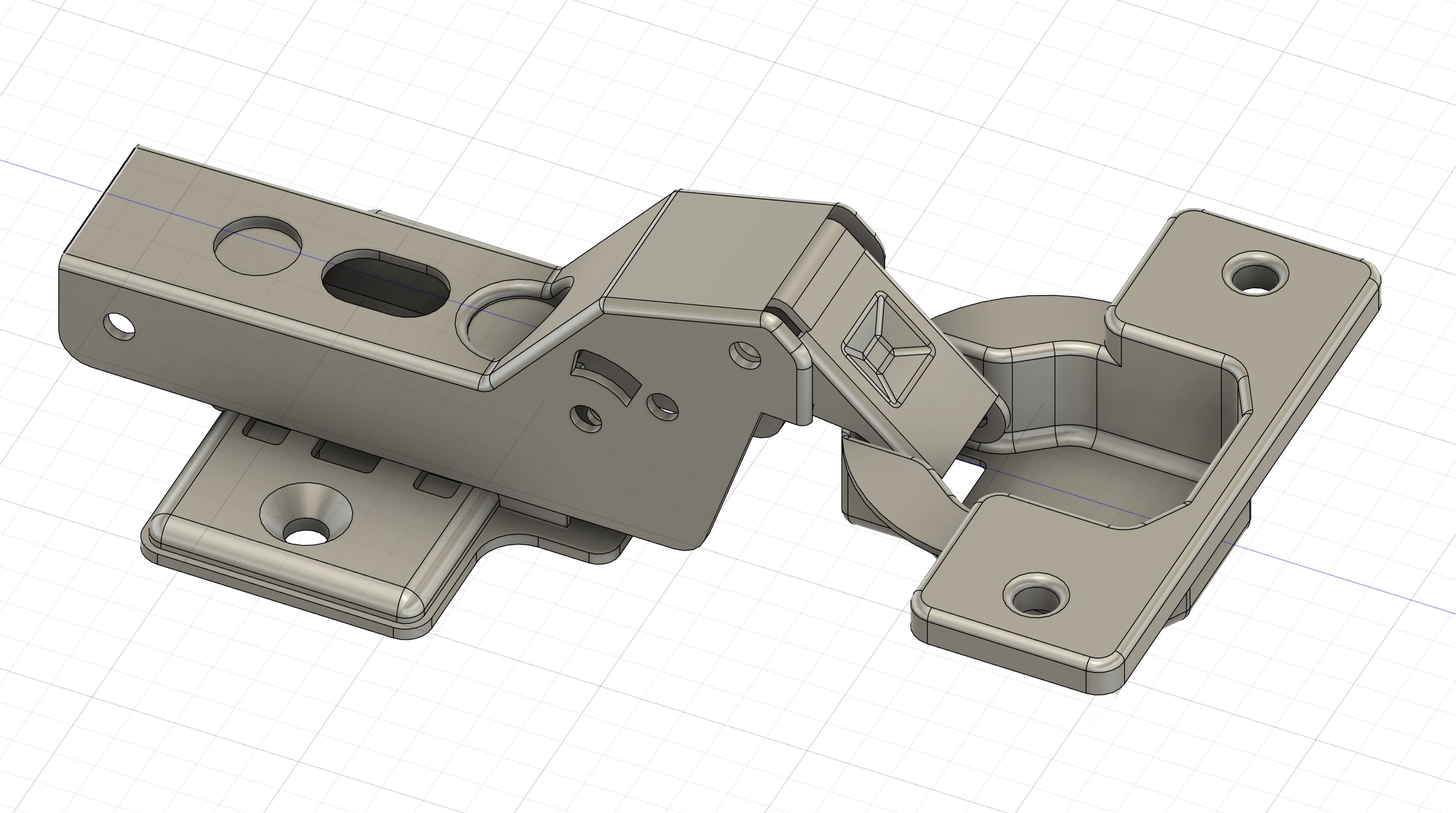
After the drawers were assembled, the next step of the desing was adding the doors. I found a hinge model on McMaster Carr where I used a series of joints to simulate the motion of the part.
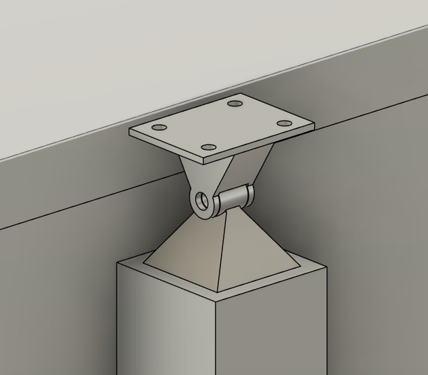
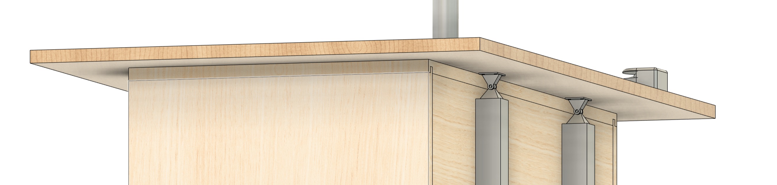
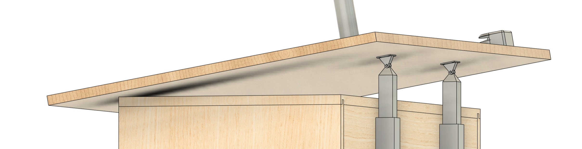
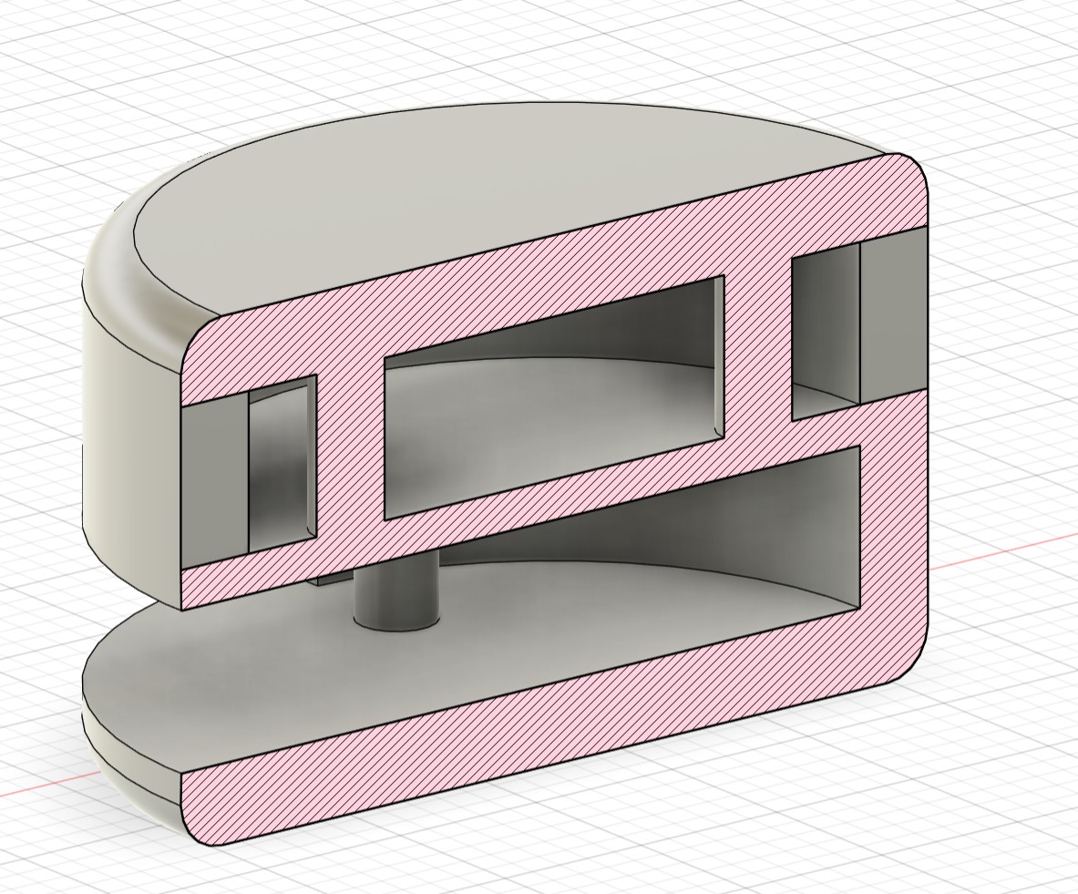
The next part of the design was trying to implement the pivoting table top function. At home, I have my dad's old drafting table in my room and I tried to model
a similar mechanism. There are two pivot joints on the underside of the far side of the table which are connected to square stock that is in sleeves attached to
the frame. When the square stock moves up in the sleeve, the table pivots and rests on the front edge of the frame.
This is the design of the tube, sleeve, and cleevis/pin joint used for the motion of the table top.
At this point, all of the main functionality of the workbench has been achieved. I managed to model the functioning drawers, doors, and pivoting table top which were the main goals of the design. For the next part, I chose to add some of the smaller features. I had a long list and chose two to move forward with: a drafting arm and the light.
Regarding the two smaller features, I was more interested in the drafting arm, inspired by old vemco drafting arms. I learned about the tool over the summer when I started watching a lot of a youtube channel named Inheritance Machining. He is a machinist who hand draws most of his designs using a drafting arm. With that being said, I therefore spent more time on the drafting arm than the light.
In order to make the light, I drew a circle on the desk top, and extruded it as a new body and then used revolve joints and a few additional sketches to make the shape
of the light. I then added the rotary joints between the two joints on the light as well as between the light and table top. I also wanted the light to move with the table
which took some finagling. I had to move the light into the component that was the table top and then cut a hole into the surface that would be hidden so I would have a
reference point I could use with the light body to form the joint. Using a sketch wouldn't work because the sketch doesn't move with the table top and thus neither would
the light.
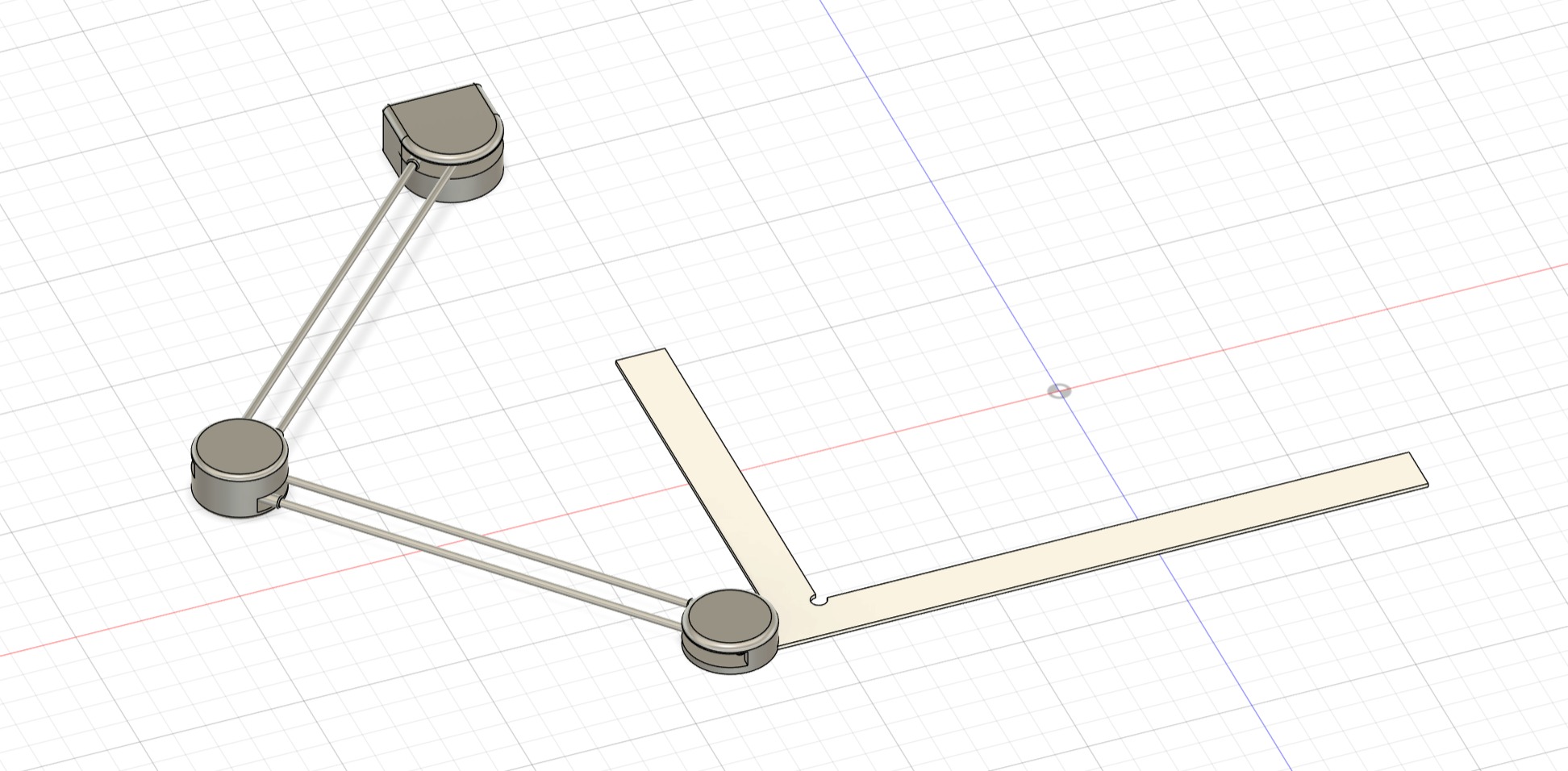
For the drafting arm, I made it in a completely different file and then imported it into the work bench file. I chose to do this as I was going to have to design a few different,
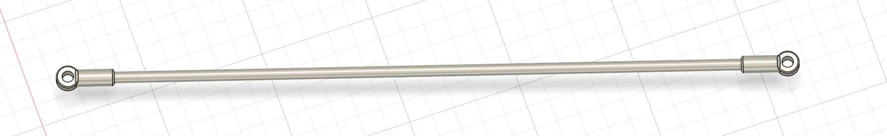
components and I figured it would be easier to start fresh. The design works based on using connecting rods to form pivoting parallelograms enabling the motion while keeping the
square used for drafting true to the surface beneath it. The rod was a simple circular extrusion and then the two pieces at the end serve as attachment points to the pins in
the other parts of the design.
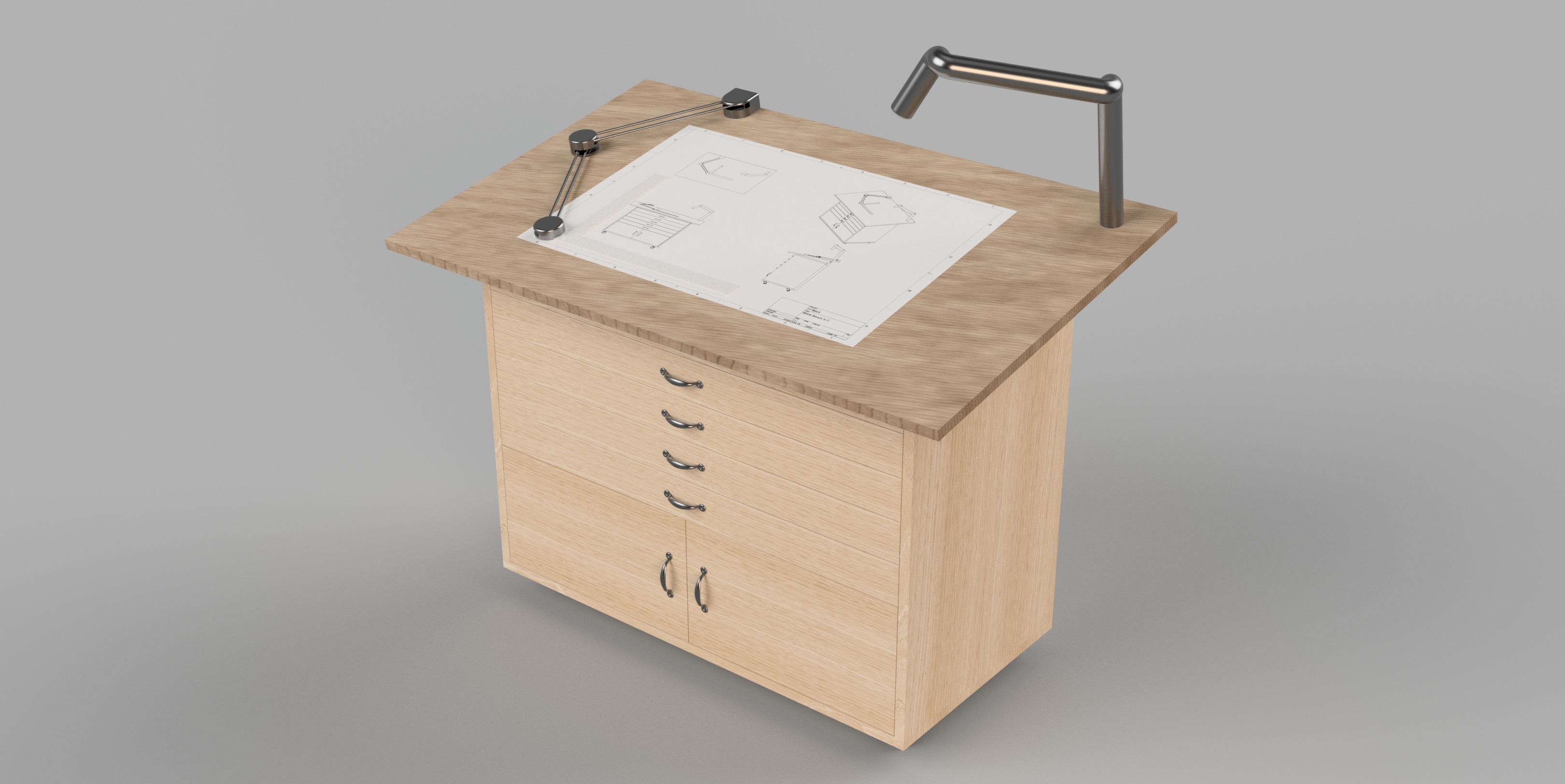
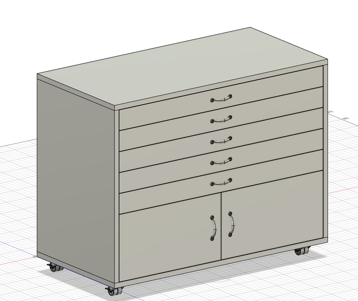
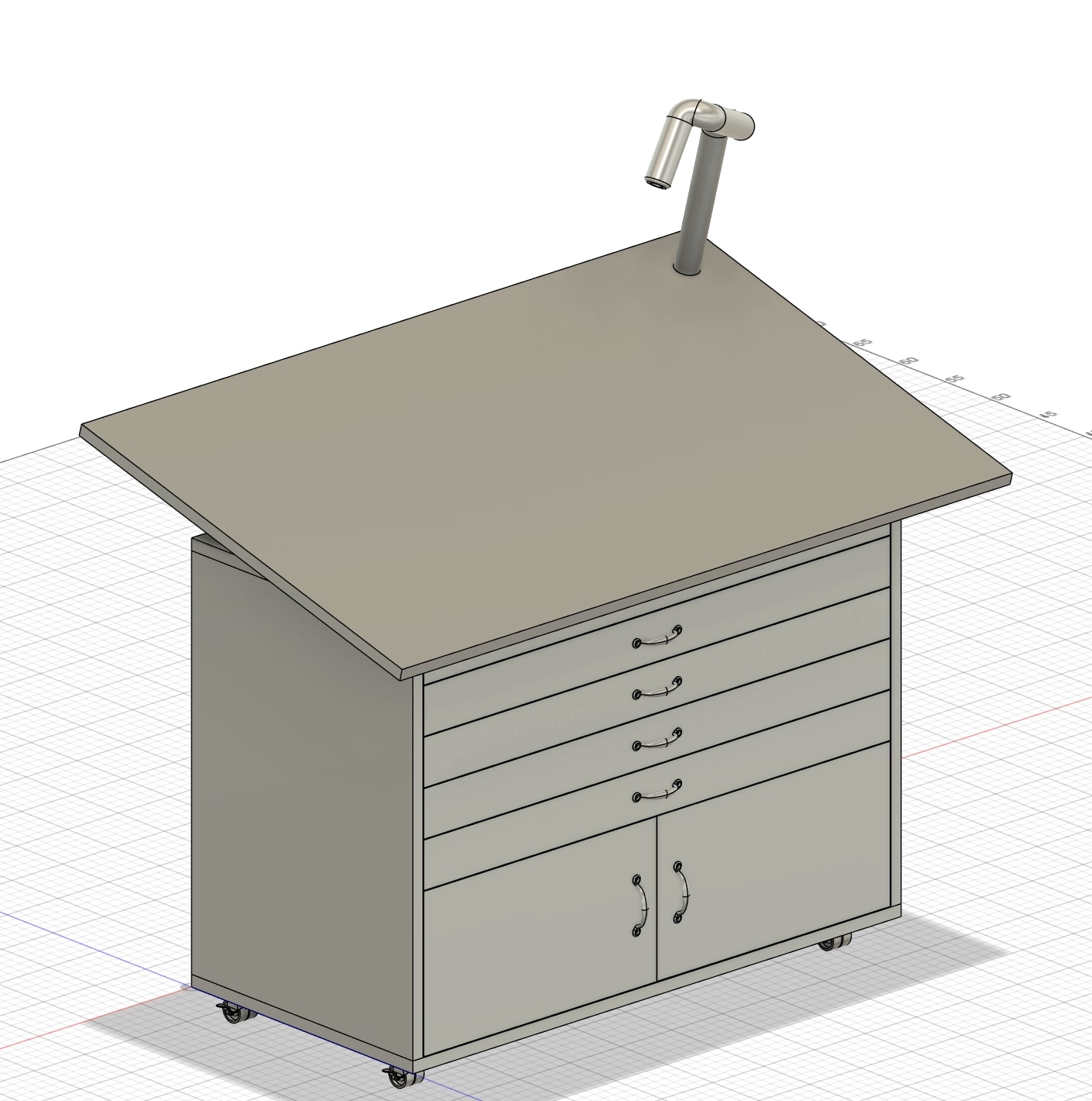
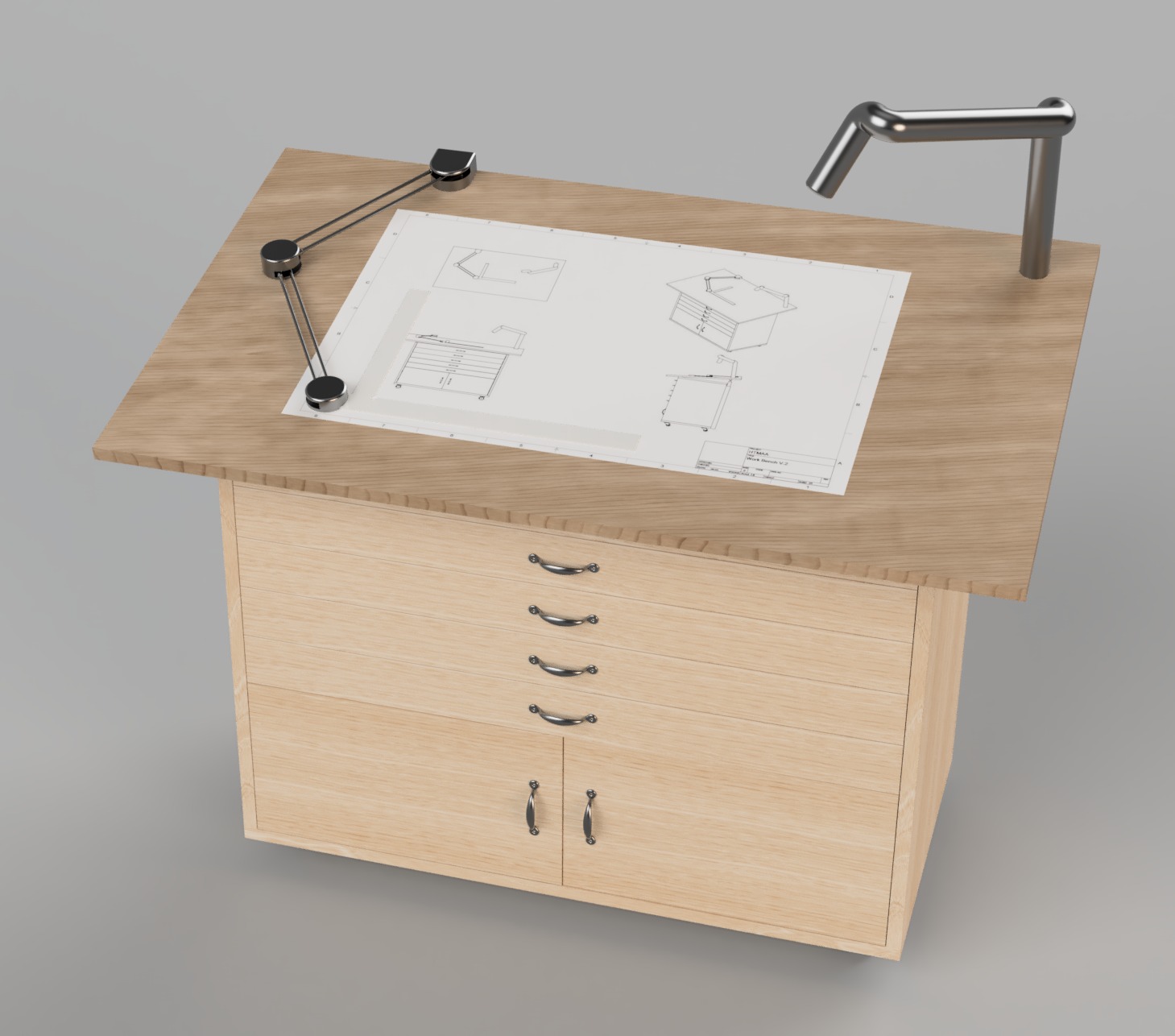
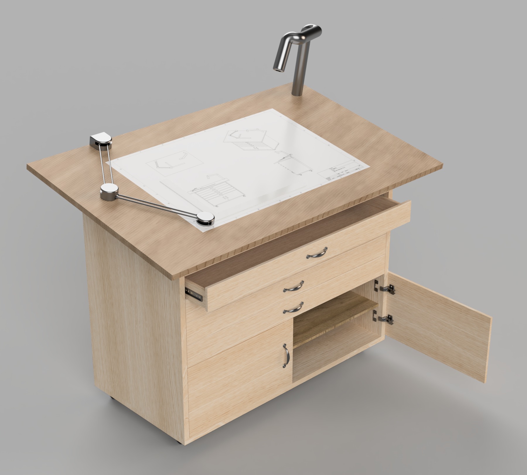
With that, everything has been modeled! To add a little bit more detail to the design, I used Fusions drawing feature to make a drawing of the workbench model and imported it as a canvas onto the table top. I then switched to the rendering tab and used the appearcance feature to model the material of the design. I used oak for the frame, drawers, and cabinets and then semigloss maple for the table top. For the light, pivot system, and drafting arm, I left them as the satin steel. Here are the final renders!
Thoughts and Reflection
Overall, I think the project was a success. I think I was a little overambitious with the number of features that I wanted to add to the final design but I think I chose the most important to focus on. I had a good amount of experience with Fusion going into the week and so it was a good opportunity to learn some new features and work on ones that I never quite understood before. One of them was the parametric design feature, I didn't know about it before this week and it makes such a huge difference! I will definitley be using more in the future. Another thing I focused on was trying to make each sketch fully defined which I don't think I've neccesarily done before. I also spent a good amount of time this week working with joints and trying to figure out how to coordinate different motions so they work together as part of the larger design. One thing to note was that the rotary joints are quite finicky. They seem to reset themselves anytime the edge of their bounds is reached making them slightly difficult/frustrating to work with. I also learned, at least on a surface level, how to use the rendering tool and I was amazed at the results! I look forward to using it for my future projects.