Week 1: Computer Controlled Cutting
This week there are two assignments in addition to making the website, using the laser cutter and using the vinyl cutter. I'm going to split the documentation for each into different sections.
Project Plan
I've been thinking about what I might want my final project to be and one of the ideas was a modular robotics system. With that being said, I figured an assembly kit would be the perfect place to start modeling the idea. I sat on my couch for a while wrestling with ideas until I came up with what I think should be a comprehensive system for what I want to achieve. I grabbed my notebook and started sketching the ideas.
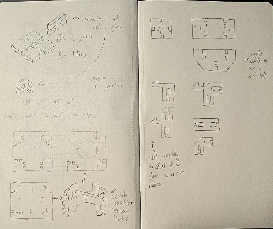
The goal is to make a system of tiles and connectors. The tiles and connectors use the pin joints Neil showed in class. I think the most interesting part is
the rotation system that I want to try and implement seen in the bottom left corner of the drawing. I want to make a tile that something can snap into and stayed
fixed too, but then I want a separate tile, one with a circle that can snap onto the other side of the connector and pivot around it enabling rotation. This would
be usefule for modeling many kinds of robotic joints.
After walking into lab and seeing how thick the cardboard was, I realized that the snap joins for rotation would not have worked and so I decided that I would use
a pin joint locking the rotation cross to the circle and cross tiles.
Execution
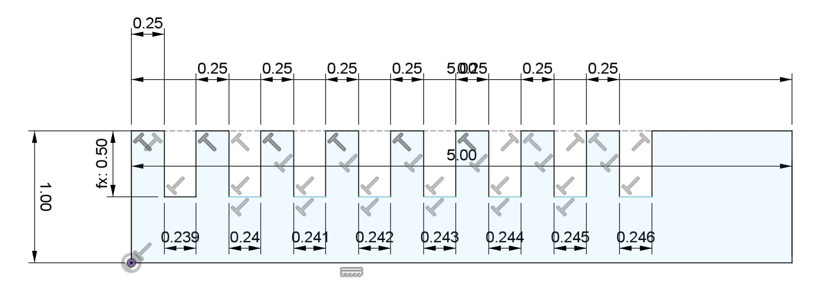
After some testing, I found that a gap of .24 was the best width for the press fit joints. I then modeled all of the features that I
would need for my model to test the fit before I made the final designs. The two main components I tested were the connector mechanism as well as the rotation
mechanism.
The second round of testing focused on making the features function and less about the fitting as that was all primarily solved after finding the best thickness to use.
The main aspect that I wanted to focus on was the rotation joint, arguably the most important part of the project. I did this by making a few different
sized circle tiles based on the radius of the cross it would be rotating around and then test fitting them and seeing whether or not I liked the rotation action.
I did three different circle sizes, each in .005" increments. Due to the thickness of the material used for the cross, I couldn't just use the same radius as before.
I projected the cross onto the sketch and then used its corner as the starting reference mark for the first circle radius. The other test circle sizes got incrementally
smaller.
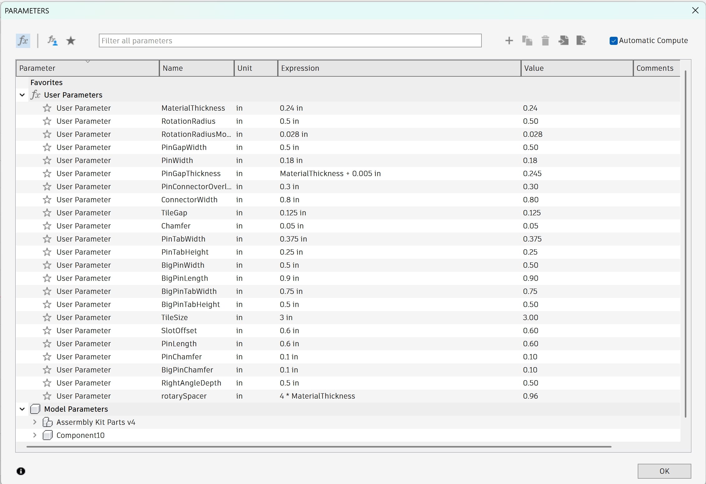
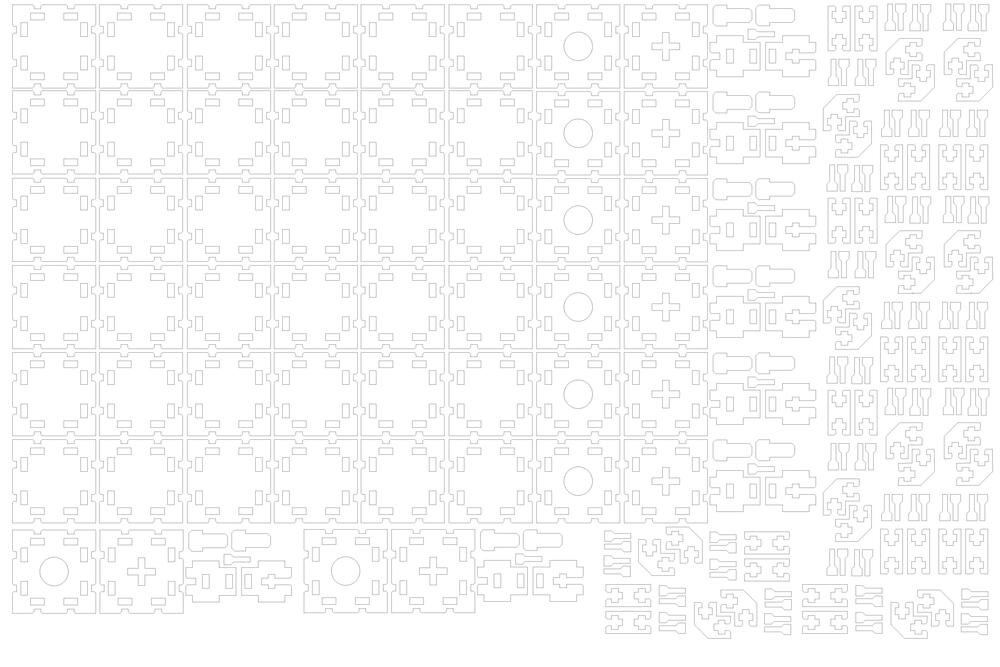
Once I was comfortable with the smaller models I started a new file for the final design in Fusion. I started by spending a fair amount of time making the parameters
that I thought I'd need for the design based on my test parts. After having all the parameters, I began working on the final sketches making sure that they were fully
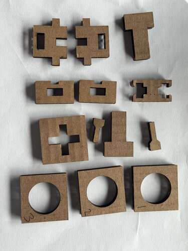
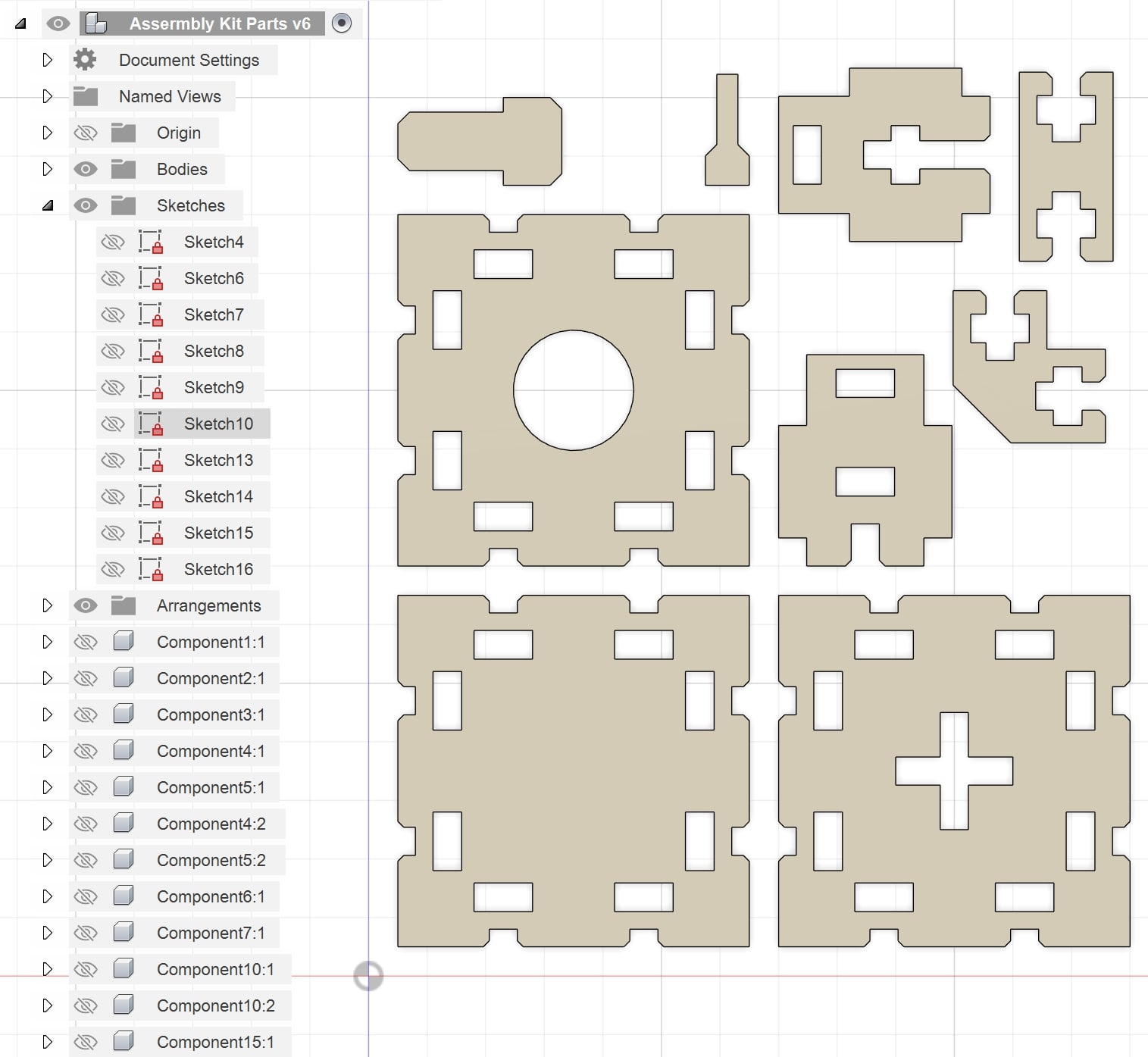
defined and parameterized. Every so often I would go an change one of the parameters to make sure that everything adjusted appropriately. Here are the final designs:
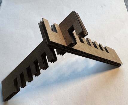
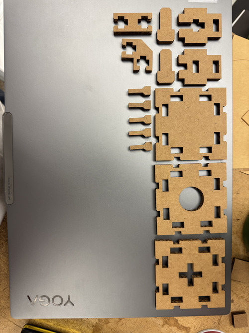
Once I had the final shapes, I exported the sketches, exluding the construction lines, as DXFs so I could import them into Rhino to print. I made a test file that would
print one or two of each component to test the fit and go back and adjust any of the parameters if neccesary. You'll see why later, but I found this small test file quite
helpful for testing new cut settings. Coincidentaly, the cut file could be assembled into something that looks like a swivel chair and so I have ended up with a few of them...
When learning to use the laser cutter, I was told to use less power and cut twice to increase precision and reduce burning. That was fine for small test cuts, but
when it came to the mass cut of all the tiles, it was increadibly inefficient. Each cut was around an hour. What I should have done was more testing at the higher
power settings, determine the new "MaterialThickness" that I should have used and adjust my designs if neccesary with the parameter. With that, I could then
do it all in one cut and it would have been far more efficient.
I wrote the section above while the second cut of the first mass cut was still happening. After it finished I learned that it didn't go all the way through the cardboard
and so I'd have to sit there and finish cutting them all out by hand, run the program again, or change the settings and cut it all again... I decided to test for new settings
and start the cuts over.
After some testing, changing both the power and frequency, I found that speed = 30 power = 35 and frequency = 900 worked best for the 120 watt epilog. These settings enabled
the parts to drop out of the cardboard after one cut. While testing for these new values, I was doing so by cutting more test combs that I used earlier to see if my
"MaterialThickness" parameter would have to change for my models. Surprisingly, the .24" was still the best fit and so I kept it. I did one final test cut of each module using the small
test file mentioned earlier to make sure that each component functioned as needed. They all fit together using the new settings and so I moved on to preparing the new mass print file.
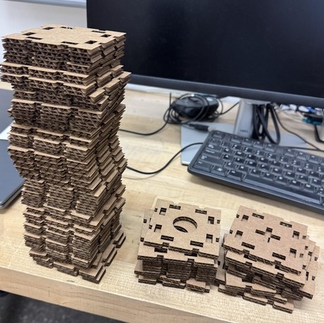
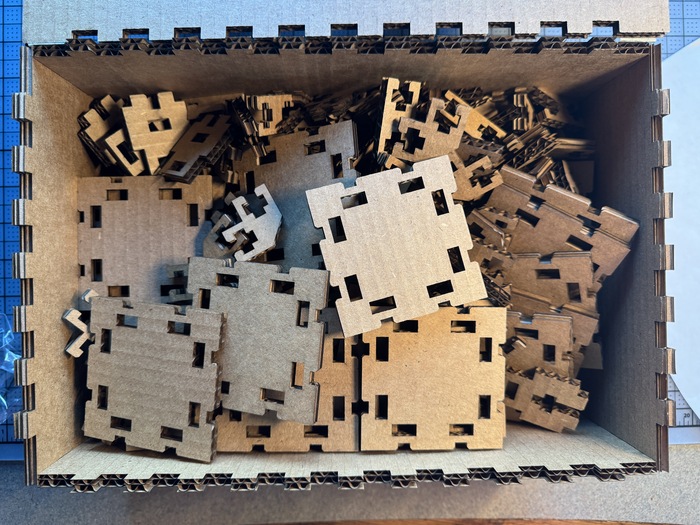
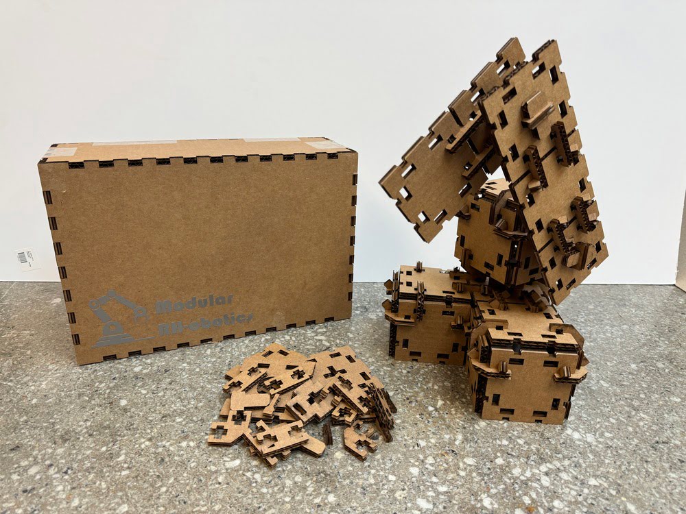
During the first attempted mass cut, I realized that due to the number of parts that I was cutting, I wanted a way to store them so that they wouldn't be loose and all over
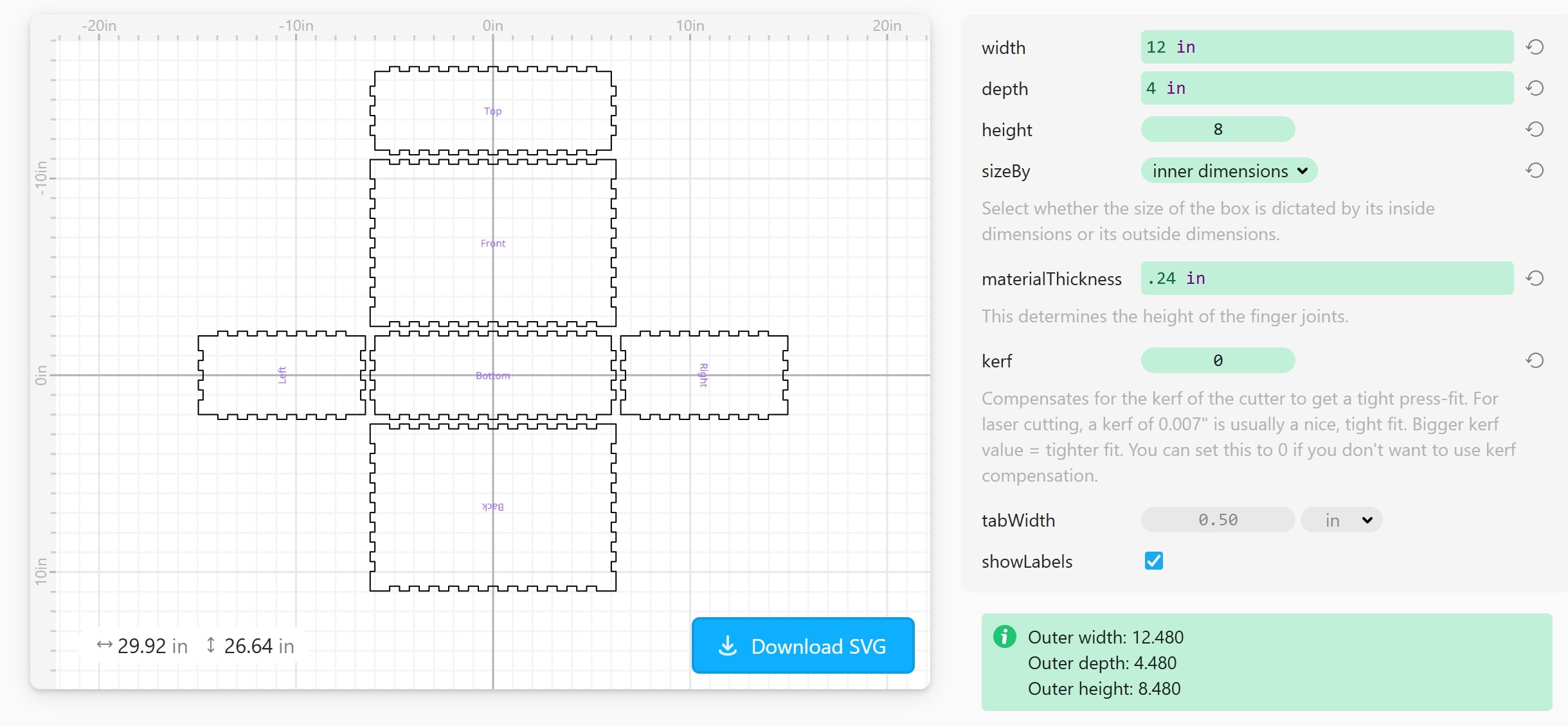
the place, a box seemed perfect. Going through the class website, I found a link to Cuttle, a website that allows you to find existing desings and customize the parameters for your needs. I used this to make the design for a box to hold all the pieces.
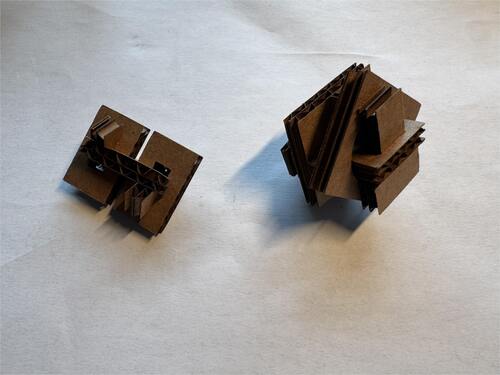
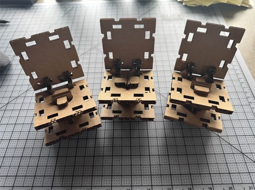
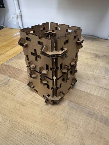
Some assemblies!
Thoughts and Reflection
I think that I was definitley a little ambitious this week with the scope of my project. The idea itself was totally fine, but the decision to make a giant kit and print dozens of
each kind of part so I could assemble larger structures might have been a little unnecessary. Given the number of pieces I was cutting though, I thought it provided a great opportunity
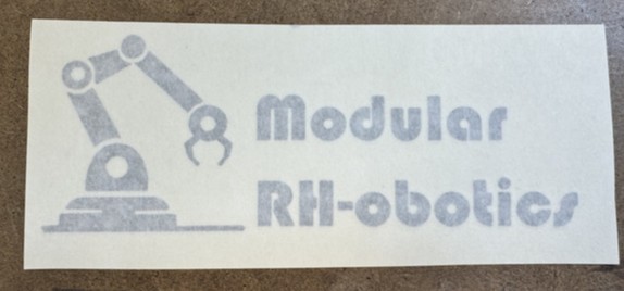
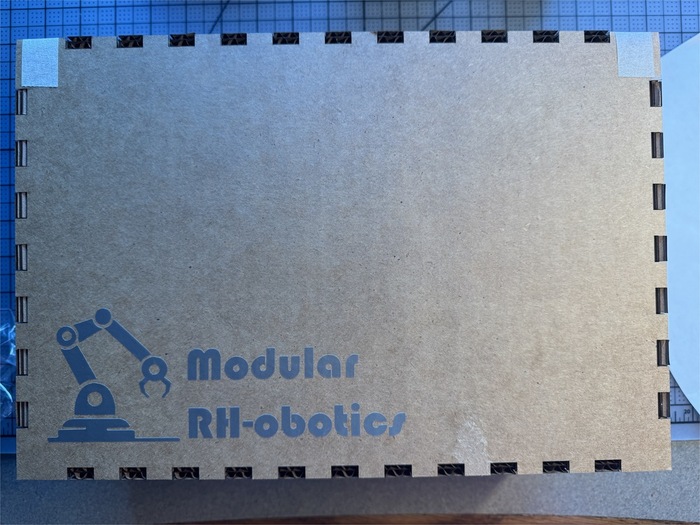
to learn/work with Cuttle and gave an excelent use for my vinyl cut sticker, tying both tools of the week together into a single project.
I am a little disappointed though, many of the pins that I got out of my final mass cut are somewhat loose. I think it has to do with some warp in the cardboard I was using, changing the
height and therefor the focus of the laser and kerf. I decided that it was not worth cutting a whole new batch as it was already 2:20 in the morning and they all functioned, despite
being slightly loose. Next time, I would just be more cautious about checking my cardboard and perhaps check the focal length in a couple areas along the cut bed.
The overall execution of the idea I'm quite proud of. I've never designed something like this before and it was a very interesting challenge, trying to make something so
that it can be assembled in many different ways. Normally, when I design something, I only think about the way that I envision it to be assembled, in the past, there has
only ever been one. This week, however, it was cool to break that trend and design a method of construction, not just a single construction.