Week 11: Networking and Communication
Project Plan
I figured that this woudld be the perfect week for me to try and make my boards start talking to eachother. To do that though, requires actually having the board. In addition to that, I wanted to design the next version of the linear actuator so that it was more robust and had the built in options to attach a VL53L1X sensor and a limit switch for homing. Later in the week, on my train ride home, I ended up designing my first attempt at a solver for inverse kinematics of an arbitrary N segmented 2D arm.
Conversation with Anthony
The center point of the conversation was wiring and communicating between the boards. Originally I wanted to do the communication over wifi
and in an ideal world, I would also somehow power the actuators through the connection of the actuations to the joint system itself, with no external
wires. I conceded to external power a while ago as that is a complicated problem that is not the highest priority, perhaps it can be revisited after the
semester. Anthony argued that if I was already going to be running cables, there was no reason that I couldn't also run the communication through wires
which would greatly simplify things. We decided that I would try and do the communication using I2C protocol and run something once the actuators are connected
to do a form of daisy chain addressing like is done with Neo Pixels that way whenever the actuators are connected, the order doens't matter. He suggested that
I use a ribbon cable to split the power over multiple wires and then have the coms so that everything is only running through one wire. He also suggested that I
switch from using the ESP32 C3 to the S3 as it in general a more powerful board that would provide more opportunities in the future. With either board, I still
leave myself with the option to explore wifi communication in the future.
We also briefly discussed the connection system and I think it would be interesting to try and use carbon fiber rods as the main structural component of
the system and print the individual connectors. This then led into the idea of having most of the design be skeletal so you can see into the compomponents and
or actuators to see exactly what is going on which I think would be pretty interesting.
Execution
Alright lets do some Networking! I did a bunch of other work while also working on this weeks assignment. In an ideal world, I would have just done this on the
boards for the actuators but I did not have time to finish designing the PCB and mill them and so I had to come up with something else. I had some ESP32 C3 Super
Minis lying around and so I figured I'd give it a shot with those. The plan was to simulate the PCB on a bread board and make a couple of them so taht I could
effectively recreate the modular aspect of the system.
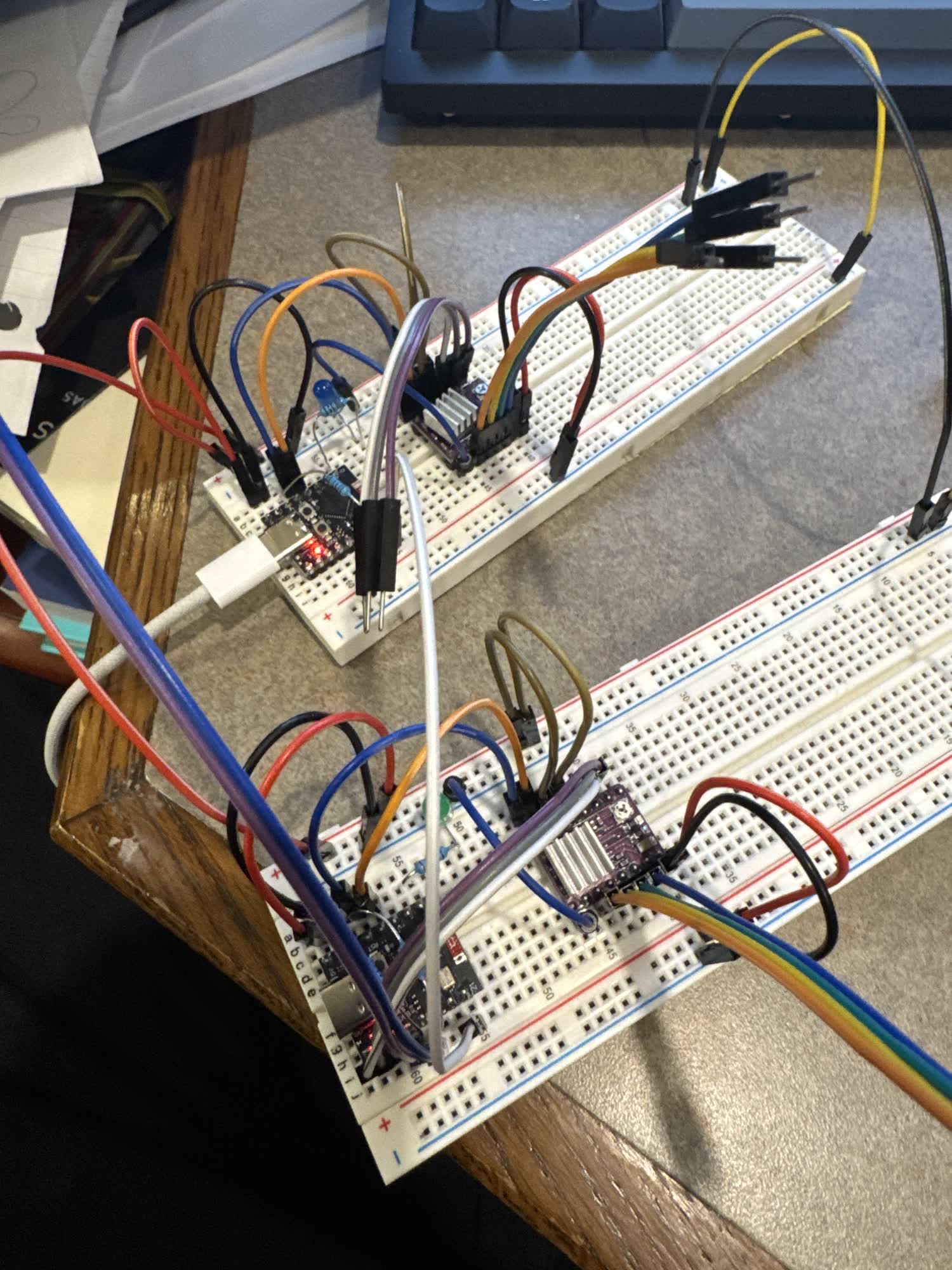
I then wanted to make sure that the drivers were working and so I hooked up the cycloidal drive to each as a test which ended up working fine.
Now I started trying to do the communication. I looked through the code that Neil posted on the class website and didn't find anything
that would work in particular and so I went to Gemini. In the past I have used ChatGPT but now that Gemini 3 is out, I wanted to give it
a try. I've attached all of the conversations below.
Long story short, I haven't gotten it working yet. I tried a ton of different things. The general idea of the code that I wanted to run was
that the main board, the one plugged into my laptop, would send signals through an additional pin, not just through SDA and SCL to "wake up"
the next board in the chain and assign it a new address. it would then try to start sending messaged ove I2C to that address. Throughout all
of my testing, I never got it to detect the secondary board through I2C.
The SDA and SCL pins on the ESP32 C3 Super Mini are 8 and 9 respectively, coincidentally pin 8 is also the pin for their builtin LED. During one of
the tests, both boards' built in LED starting blinking synchronously with each other which indicates that there is something going on. I thought this meant
that there was some form of communication happening but that maybe the LED was interfereing with the signal.
In the data sheet for the Super Mini, it said that the ESP32 C3 supports multiplexing and that you could use almost any GPIO for the I2C communication and so
I thought I'd try switching them to see if that would solve the problem... it did not. I originally tried switching to pins 3 and 4 and then 9 and 10 and those
also did not work. I tried reducing the problem and switching to just have an I2C scanner on the main device to see if it could detect the secondary and it never did.
So I've isolated the problem to the fact that it is unable to detect the microcontroller as an I2C device.
There are now two paths that I can go down: I can either swtich and try to use serial to communicate which would also eliminate the need for the seperte assignment as
the serial would solve that inherenlty. I might also swtich MCUs and test to see if those would work better. I have two ESP32 S3 that I got from Jen that I was planning
on using for the prototype boards once I made them but the communication seems more important right now and if those are the boards I will be using, I think its important
to start working with them sooner rather than later. I want to quickly try serial and I also think I am going to switch to using the S3s. I am going to continue working on
this while I am home and figure out exaclty what went wrong and how to fix it.
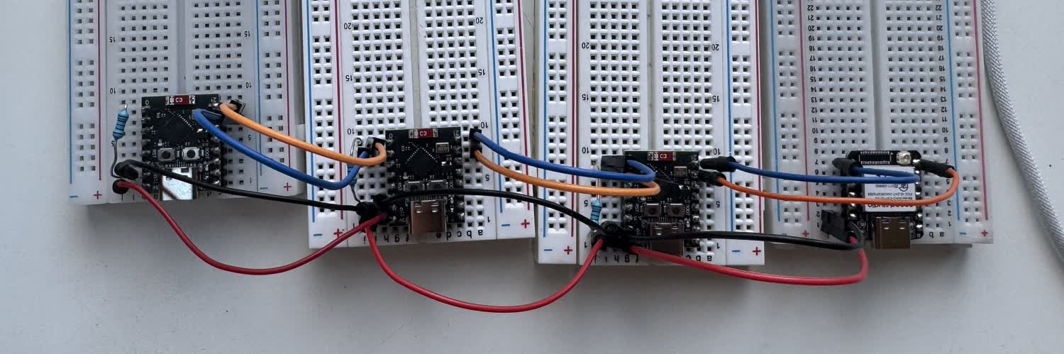
The evening after class this week I sat down and tried to figure it out. During lecture, instead of doing the random generator Neil offered up the time for people to ask
questions about their final projects to try and solve problems. I asked about my communication issues and he recommended that I take a look at the broad hop method.
The way that the broad hop method works is by chaining a bunch of MCUs together and have them communciate over serial. You use your commputer to send an intial command
and then the first board passes it along and then also processes the command. If the command is talking to that board, it acts on it. If it is not, then it does nothing
and has already passed it on. On my computer I'm using python to communicate with serial, sending bytes that the MCU's can process. I started with Neils code and gemini to make sure
I understood exactly what the code was doing and then modified it slightly to work with the microcontrollers that I was using. The conversation I had with gemini can be found
at the bottom of the page. I wanted to just make sure that I could get it all working.
The three secondary nodes are ESP32 C3 Super Minis the main board that interfaces with my computer is a Xiao ESP32 S3. There is no reason for them to be different, thats just what I had.
The next part of this will be to pass bytes that enable the control of stepper motors.
I got the stepper control working! I talked to gemini to talk through how I wanted to approach the problem and modify the code that I had already gotten working with the
LED version of the broad hop and then went ahead and implemented it. I wanted to be super careful about not interupting the motion of the stepper and also the flow of
communication between the computer and the microcontroller. All of the conversations with Gemini from the week can be found below along with the code that we wrote.
There were a few changes that I made during the process of adding steppers. For one, I eliminated a lot of unnecesary code on the first node that wasn't connected to anything
so that it can serve purely as the communication node between my computer and the rest of the system. It won't recieve an address during addressing, it simply passes all of
the packets down the line. It's needed though as one node has to be listening to the serial port connected to the usb-C and the others need to be listening to serial ports
connected to the GPIO pins.
Heres a brief overview of how the code on each node works. Upon initilialization, it sets its address to 0 and does a bunch of pin initializations for the stepper motor,
LED, and serial ports. It then opens up and incoming and outgoing serial port to listen for and send along commands down the chain. Currently there are five commands that
have been implemented: move a single motor, control LED, auto-address, prep motor location, trigger motion. The reason that there are multiple motor commands is to differentiate
between moving one motor and moving multiple at a time. Each command as a series of 8 bytes in an ordered sequence: Starting
character, address, command, data (4 Bytes), end character. Sometimes the data is only a single byte, for example 1 to turn on an LED, whereas for the steppers the data is
4 bytes in order to send more than 255 steps, the max number that can be stored within one byte, 2^8. With four bytes, the maximum number is now
4,294,967,295 (2^32) when it is unsigned. This enables more than enough steps for the actuator. Each address and command has its own unique byte and
so by sending the bytes through the daisy chain, each node can process it to see if it was meant for them or not. There is also a universal address which can
be used to communicate to all the nodes at once.
Here is a video of all of the components working. My computer is running a python file that I worked on with gemini, which also can be found below. It establishes
the serial port and then sends the addressing command and prints how many nodes it found. It then runs a while loop that turns on each nodes LED, and then
drives the steppers individually, and then uses the prep location function to store locations for both motors, and then trigger the motion with one command
addressed to all nodes.
Thoughts and Reflection
This week I made a ton of progress on my final project which is all documented on my final project page. I got the cycloidal drive working, revised and made the next
iteration of the linear actuator. I also wrote a version of the FABRIK inverse kinematics solving algorithm and also designed the first version of the PCB that will
be attached to each actuator. I was super happy with all of that progress and am looking forward to continuing to push forward.
As for the networking, it proved to be more of a challenge than I was anticipating. In hind sight, I can point to the fact that I was trying to use the wrong protocol for
communication and I should have just started by trying to use serial for communication. If I had, I think I would have had a much easier time, I mean I was able to get it
done last night after class. I'm looking forward to trying to get the boards to run the stepper drivers next.
Updated After change to Serial:
I'm actually quite happy with the communication system now, the nodes are able to listen for additional commands while still executing the previous command. I was nervous about
the microcontrollers blocking communication when the stepper motors were running but I was able to avoid that. There are still more commands that I would like to add. Stop and resume
commands would definitley be nice. I think it would also be nice to be able to create programs tying multiple motions together which would be some form of save and replay feature.
All in all though, this was a major part of the project that got figured out this week and I'm super happy with how it turned out.
Code Files
- ⬇ Main Board Code (S3)
- ⬇ Secondary Board Code (Super Mini)
- ⬇ Serial Communication Test
- ⬇ Refined Main Board (S3)
- ⬇ Secondary Board Code with Stepper Control (Super Mini)
- ⬇ Serial Communication Python with Steppers